1
USBula – Serial to USB-Flash-Drive Bridge Firmware
User Manual
USBula is a ready-to-use firmware for accessing USB flash drives from your application over a
simple serial protocol. It runs on a Microchip PIC24FJ64GB002 microcontroller available in four
different packages (SMD and THT). For commercial applications, there is a one-time license fee
model, which limits the production costs to the actual part costs. The PIC24FJ64GB002 is available
from many distributors, some with the option for pre-programming the controllers.
Features
•
•
•
•
•
•
•
Connects USB memory stick to your application without USB programming
Ready to flash binary files (HEX format, supported by most programmers)
Runs on well available PIC24 microcontroller (on stock part from many distributors)
Free version for evaluation and personal use
Source code available (via license option) – modify it for your needs
+5V tolerant serial interface with simple protocol for file access
FAT16/FAT32 is supported. 8+3 character filenames are used.
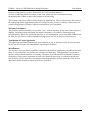
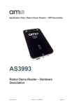
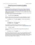
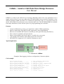
Typical Application
Your Application
Microcontroller
UART
PIC24
USB
USB flash drive
flashed with USBula
Examples: Data logging, load/store configurations, firmware updates
Code example
Serial.print("U\n");
while (Serial.read() != '\n');
Serial.print("O1A:test.txt\n");
while (Serial.read() != '\n');
Serial.print("W10b\n");
while (Serial.read() != '\n');
Serial.print("Hello World");
while (Serial.read() != '\n');
Serial.print("C1\n");
while (Serial.read() != '\n');
V1.2 © 2014 [email protected]
//
//
//
//
//
//
//
//
//
//
sync (baudrate detection)
consume response
open file (id 1, append mode)
consume response
prepare write of 11 bytes
consume response
write data to file
consume response
close file
consume response
USBula – Serial to USB-Flash-Drive Bridge Firmware
User Manual
Table of Contents
1 Integration Guide..............................................................................................................................3
1.1 Hardware.......................................................................................................................................3
1.1.1 Chip packages.............................................................................................................................3
1.1.2 Pinout Description......................................................................................................................3
1.1.3 Schematics example...................................................................................................................4
1.1.4 Supply voltages: +3.3V and +5V...............................................................................................5
1.2 Load USBula HEX-File................................................................................................................5
1.2.1 PicKit3 and MPLAB IPE...........................................................................................................5
1.2.2 Order pre-programmed chips.....................................................................................................6
2 Serial interface..................................................................................................................................6
2.1 Interface mode selection................................................................................................................7
2.2 UART communication...................................................................................................................7
2.3 Communication protocol...............................................................................................................7
2.4 Command description....................................................................................................................8
2.4.1 „V“ – Get Version String............................................................................................................8
2.4.2 „O“ – Open file...........................................................................................................................8
2.4.3 „C“ – Close file..........................................................................................................................8
2.4.4 „R“ – Read..................................................................................................................................8
2.4.5 „W“ – Write................................................................................................................................9
2.4.6 „U“ – Synchronize/Alive............................................................................................................9
2.5 Response codes..............................................................................................................................9
2.6 Example.......................................................................................................................................10
3 Licensing........................................................................................................................................10
3.1 License options and pricing.........................................................................................................11
3.2 License terms...............................................................................................................................11
V1.2 © 2014 [email protected]
2/12
USBula – Serial to USB-Flash-Drive Bridge Firmware
User Manual
1 Integration Guide
This section describes how to integrate USBula into a customer application design.
1.1 Hardware
USBula runs on a Microchip PIC24FJ64GB002 microcontroller. The following guide is intended to
help the developer integrating this controller into the customers application. This information is
only a prosposal whitout any guarantee on correctness. Please consult the PIC24FJ64GB002 family
datasheet for obligatory details. This datasheet also includes „Guidelines for getting started with
16-bit microcontrollers“ (Section 2.0) with useful information about required external components.
PIC24FJ64GB002 product page with link to the datasheet.
http://www.microchip.com/wwwproducts/Devices.aspx?product=PIC24FJ64GB002
1.1.1 Chip packages
The PIC24FJ64GB002 is available in different chip packages. The package which fits to the rest of
the customers design can be used.
28-lead QFN
28-lead SOIC (0.3“)
28-lead SPDIP
28-lead SSOP
These are the part numbers of the available package types.
Package Type
Shipped in Tubes
Shipped as Tape/Reel
QFN
PIC24FJ64GB002-I/ML
PIC24FJ64GB002T-I/ML
SOIC (200 mil)
PIC24FJ64GB002-I/SO
PIC24FJ64GB002T-I/SO
SPDIP
PIC24FJ64GB002-I/SP
SSOP
PIC24FJ64GB002-I/SS
PIC24FJ64GB002T-I/SS
1.1.2 Pinout Description
The following table lists the pins which are used by USBula. It describes which function is mapped
to pin numbers of available package types.
SOIC
SPDIP
SSOP
QFN
Function
Description
13, 28
10, 25
VDD
+3V3 Power supply
20
17
VCAP
Voltage regulator output. Connect capacitor to this pin
23
20
VUSB
USB voltage: +3V3
V1.2 © [email protected]
3/12
USBula – Serial to USB-Flash-Drive Bridge Firmware
User Manual
15
12
VBUS
USB voltage: +5V
8, 27
5, 24
VSS
Ground supply
19
16
DISVREG
Disable voltage regulator. Connect to GND.
9
6
OSCI
Oscillator: 12 MHz crystal.
10
7
OSCO
1
26
MCLR
Reset input
4
1
PGED1
Programming data (optional for in-circuit programming)
5
2
PGEC1
Programming clock (optional for in-circuit
programming)
18
15
RP9
RX
UART receive signal
11
8
RP4
TX
UART transmit signal
2
27
RA0
3
28
RA1
12
9
RA4
MODE0 Internally pulled up to VDD.
MODE1 See section „Mode-Selection“.
For UART-Mode: leave pins open, not connected.
MODE2
24
21
RB13
CFG0
25
22
RB14
CFG1
26
23
RB15
CFG2
Internally pulled up to VDD.
See section „UART configuration“.
For Autobaud: leave pins open, not connected.
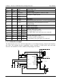
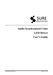
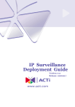
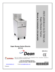
1.1.3 Schematics example
+3 V 3
+3 V 3
The PIC24 needs only a few external components to act as bridge between a simple serial interface
and USB. This diagram shows a mimalistic circuit, running in UART mode with auto-baud
detection. Pin numbers for SOIC, SPDIP, SSOP packages are shown.
13 28
C7
8 27 100n
10 G N D 9 +3 V 3
Q 1 23 C4
C 5 C 9 2 2p
2 2p 1 00 n G N D G ND
G ND
+
1 2M H z 20 C 6 15 4 ,7 u G N D 19 M C LR V D D 1 V D D 2 V S S 1 V S S 2 R A 3/O S C O R A 2/O S C I V U S B V C A P /V D D C O R E V B U S R A 0/R P 5 R A 1/R P 6 R A 4 R B 0/R P 0/P G E D 1 R B 1/R P 1/P G E C 1 R B 2/R P 2 R B 3/R P 3 R B 4/R P 4 R B 5 R B 7/R P 7 R B 8/R P 8 R B 9/R P 9 R B 10/R P 10/D + R B 11/R P 11/D R B 13/R P 13 R B 14/R P 14 R B 15/R P 15 2 3 12 4 5 6 7 11 14 16 17 18 21 22 G N D IC S P nb
O p tio n a l fo r in circuit p ro g ram m in g
TX
RX
To h o st co n trolle r
24 25 26 +5 V R2
250m A
D IS V R E G G N D D + D V B U S GND
G N D @ 1 GND@ 2
P IC 24 F JX X G B 0 02
USB
1 R3
1 0 0n
1 2 3 4 5 6
IC 1
1 0 k C 8 K 3 G N D V1.2 © [email protected]
4/12
USBula – Serial to USB-Flash-Drive Bridge Firmware
User Manual
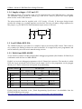
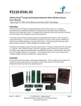
1.1.4 Supply voltages: +3.3V and +5V
The USB part needs +5V. Current on the +5V line depends on the used USB flash drive (~100 mA).
The maximum current should be limited (e.g. with a PTC fuse) to protect the circuit against
short-circuits on the USB connector.
+5 V
IC 3
GND
C 2 4 ,7u 10 0n GND
V O U T G N D C3
V IN 1
+
2 3
+3 V 3
The microcontroller must be supplied with +3.3V (needs ~25 mA). If the target design doesn't
provide this voltage yet, a voltage regulator can be used. There are out many voltage regulators for
this purpose, e.g. the MCP1700 with maximum output current of 250 mA.
C1
M C P1 700
GND
1 00 n
G N D 1.2 Load USBula HEX-File
The USBula firmware is provided in a compiled, ready-to-use binary HEX format. This format is
very common for flashing software into microcontrollers. It is supported by most programmers and
can be handled by most electronic manufacturing services.
1.2.1 PicKit3 and MPLAB IPE
A cost effective solution is a Microchip PicKit3 debugger/programmer (Part Number: PG164130) in
combination with the free tool MPLAB IPE.
PicKit3 is a in-circuit debugger/programmer with a 2,54mm 6-pin connector. The interface is called
ICSP. An 6-pole pin-header can be placed on the target circuit, so the programmer can be plugged
directly on it. These connections are required for programming:
PicKit3 Header
1 VPP/MCLR
PIC24FJ pins
SOIC, SPDIP, SSOP
QFN
1
26
2 VDD
+3V3
3 VSS
GND
Function
VPP/MCLR
4 PGD
4
1
PGED1
5 PGC
5
2
PGEC1
6 LVP
Do not connect
Further details are described in the „Flash Programming Specification“ downloadable from the
PIC24FJ64GB002 product page:
http://www.microchip.com/wwwproducts/Devices.aspx?product=PIC24FJ64GB002
V1.2 © [email protected]
5/12
USBula – Serial to USB-Flash-Drive Bridge Firmware
User Manual
MPLAB IPE is bundled with the MPLAB X IDE, which can be downloaded for free:
http://www.microchip.com/pagehandler/en-us/family/mplabx/
The IPE tool is automatically installed with the MPLAB IDE. It is available for Windows, Linux
and MacOS X.
Steps for programming with IPE tool:
1. Select Device „PIC24FJ64GB002“
2. Connect PicKit3, select it as „Tool“
3. Open USBula-HEX-file as „Source: … Browse“
4. Conenct Target with PicKit3
5. Press button „Program“
1.2.2 Order pre-programmed chips
The method described in the last section is applicable for prototypes and small production lots. For
mass production, it can be more economically to use a programming service which ships the
microcontroller already flashed packed in tubes or tape/reels. A few distributors provide such a
service, even Microchip via microchipDIRECT:
http://www.microchipdirect.com/programming/
However it is recommended to integrate the ICSP connector pads to the application circuit for
prototyping and debugging.
2 Serial interface
The host system communicates over the serial interface with USBula. This section describes how to
V1.2 © [email protected]
6/12
USBula – Serial to USB-Flash-Drive Bridge Firmware
User Manual
configure the interface and the serial protocol for accessing files on the USB flash drive.
2.1 Interface mode selection
The communication mode must be selected via the MODE0..2 pins. The inputs are pulled internally
to VDD. So the pins must left open, if high levels are expected.
MODE2
MODE1
MODE0
Open
Open
Open
All other options
Mode
UART-Mode
Reserved for future use
Currently, only the UART mode is supported by USBula.
2.2 UART communication
The UART is set up with these parameters:
8 data bits, no parity, 1 stop bit
Rx/Tx are used for communication with the host. There are no hardware handshake signals. Wiring
with the host system:
Host UART-Tx
→ USBula UART-Rx
USBula UART-Tx → Host UART-Rx
The baudrate can be selected with pins CFG0..2. The inputs are pulled internally to VDD. If high
levels are expected, the pins must be left open. If auto-baudrate is selected, the baudrate is
determined automatically while sending the first command after reset. This first command must be
the sync-command ('U').
CFG2
CFG1
CFG0
Baudrate (Baud)
GND
GND
GND
1200
GND
GND
Open
2400
GND
Open
GND
9600
GND
Open
Open
19200
Open
GND
GND
38400
Open
GND
Open
57600
Open
Open
GND
115200
Open
Open
Open
Auto-Baudrate
2.3 Communication protocol
The USBula acts as a slave device and sends only data in response to a request from the host. The
protocol is half duplex: After transmitting a request, the host must wait for the response.
The commands are transmitted as ASCII sequences. Payload data (for read/write file) can also be
binary and do not have to be in ASCII format.
V1.2 © [email protected]
7/12
USBula – Serial to USB-Flash-Drive Bridge Firmware
User Manual
Every command ends with a line break character. USBula sends LF ('\n'). When receiving it also
interprets the CR ('\r') as end of line. The maximum line length including command and paramter
characters is 128 bytes. The payload data for read and write command is limited to 100 bytes.
All numeric values are transmitted in hexadecimal as ASCII sequence. Example:
decimal: 158 → hexadecimal: 9E
Simultanously two files can be opened (maximum files opened: 2). To specify which file is
currently addressed, an identifier (called file-handler) is used.
2.4 Command description
This section describes the available serial commands. Characters sent from Host to USBula are
printed in red. The opposite direction is marked with green. Line feeds are represented by „“
2.4.1 „V“ – Get Version String
Get USBula firmware version string.
Syntax
Parameters
Example
V
vx.x.x
x.x.x = Version string
V
v1.1.0
2.4.2 „O“ – Open file
Open file with given name. The given file-handler is used to access this file with following
commands.
Syntax
Parameters
Example
Ofm:filename
>00
f: file handler
m: Mode (r = read only, w =
write, a = append)
filename: 8+3 character name
with prefixed path
Open file (handler 1) „test.txt“:
O1w:test.txt
>00
2.4.3 „C“ – Close file
Close file with given file handler. Pending data (buffered in RAM) are flushed to the USB memory
stick.
Syntax
Parameters
Example
Cf
>00
f: file handler
Close file (handler 1):
C1
>00
2.4.4 „R“ – Read
Read from given file handler the given count of bytes. If the end of file is riched, the remaining
V1.2 © [email protected]
8/12
USBula – Serial to USB-Flash-Drive Bridge Firmware
User Manual
bytes are send as „filler“.
Syntax
Parameters
Example
Rfssyy
>00
ss bytes, read from file. If end
of file riched, bytes are filled
with filler
#rr
f: file handler
ss: bytes to read
yy: filler
rr: count of read bytes (max
100)
Read 5 bytes from file (handler
1, filler: 0xFF):
R105FF
>00
Hello
#05
Syntax
Parameters
Example
Wfss
>00
ss bytes, write to file
#ww
f: file handler
ss: bytes to read
ww: count of bytes written
(max 100)
Write „Hello world!“ (=12
chars) to file (handler 1):
W10C
>00
Hello world!
#0C
2.4.5 „W“ – Write
Write to given file handler.
2.4.6 „U“ – Synchronize/Alive
This command is used to syncronize USBula to the used baudrate if configured in auto-baudrate
mode. The command must sent first, before other commands. If USBula doesn't response, the
command must be sent again after timeout. If a fix baudrate is selected via the CFG0..2 pins, this is
not necessary. The „U“ command can also be used to check if USBula is alive (like ping/pong).
Syntax
Parameters
U
>00
Example
U
>00
2.5 Response codes
USBula answers to commands with a response code which indicates possible errors.
Code
Description
>00
Successful. Everything okay!
>01
Unknown command
>02
Syntax error
>03
Invalid file handler
>04
Error while opening file
V1.2 © [email protected]
9/12
USBula – Serial to USB-Flash-Drive Bridge Firmware
>05
File not open
>06
Error while reading file
>07
Invalid size parameter
User Manual
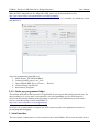
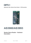
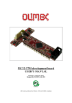
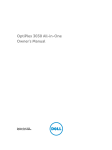
2.6 Example
The following screenshot shows an example communication. USBula is connected with a
USB-to-serial interface to an PC running „HTerm“, a terminal programm:
http://www.der-hammer.info/terminal/
The commands are just typed into the input field and sent out with enter („Send on enter LF“). The
response is shown in the „Received Data“ window.
3 Licensing
USBula is free for evaluation and personal use. For commercial purpose a license must be aquired.
Please contact [email protected].
V1.2 © [email protected]
10/12
USBula – Serial to USB-Flash-Drive Bridge Firmware
User Manual
3.1 License options and pricing
There are four different license options which depends on the purpose of use and if source code is
required.
License
Price (excl. VAT) Units
Source code
Purpose
USBula FREE
No charge
unlimited
Not included
Evaluation, personal use
USBula LE
€ 99
up to 250
Not included
Commercial
USBula LP
€ 199
unlimited
Not included
Commercial
USBula LPS
€ 399
unlimited
Included
Commercial
It is recommended to start with USBula FREE to evaluate its function and test it with the intended
system components. USBula FREE has only one difference to the other license options: it
automatically generates a file „usbula.txt“ with license information on every USB flash drive which
is plugged in.
With USBula LPS you get the source codes (MPLAB X project) and an additional documentation
which describes the firmware concept, the development environment and the steps to compile the
firmware project.
License upgrades are not possible. Please order a new license if the granted number of units are not
enough.
3.2 License terms
Software license agreement for USBula, the Serial to USB-Flash-Drive Bridge Firmware
General and Definitons
„USBula.com“ – Thomas Fischl, Schmidsberg 3, 94130 Obernzell, Germany is willing to license
the accompanying „Software“ USBula, the Serial to USB-Flash-Drive Bridge Firmware to you
(„Licensee“) only if you accept all the terms in this license agreement. If you do not agree to these
terms, do not download, acquire or use the Software.
Software License Grant
USBula.com grants the Licensee a non-exclusive license to use the Software according to the terms
and conditions defined below. With downloading or acquiring, the Licensee chooses one of the
following options:
•
•
•
•
USBula FREE: the Software is for evaluation purpose and personal use only. The use in
commercial products is not allowed.
USBula LE: the Software can be installed in up to 250 units of one specific product.
USBula LP: the Software can be installed in unlimited units of one specific product.
USBula LPS: the Software can be installed in unlimited units of one specific product.
Additionally the source code of the Software is made available for the Licensee. The
Licensee can modify and use the source codes for his needs.
USBula LE/LP/LPS can be used in any product where the Software does not represent the main
V1.2 © [email protected]
11/12
USBula – Serial to USB-Flash-Drive Bridge Firmware
User Manual
function of the device (e.g. these license does not cover breakout boards or
Serial-to-USB-Flash-Drive converters; in this case, please ask for a customized license).
Mentioning that USBula is used in the product is not necessary.
The Software uses parts of Microchip Libraries for Applications. The Licensee accepts the terms of
the underlying license aggreement (www.microchip.com/mla_license). It mainly constricts the use
to Microchip products, porting to other microcontrollers is not permitted.
Warranty Disclaimers
The Software and documentation is provided "as is" without warranty of any kind, either express or
implied, including without limitation any implied warranties of condition, uninterrupted use,
merchantability, fitness for a particular purpose, or non-infringement. In no event shall USBula.com
be liable for any direct or indirect damages arising in any way out of the use of this Software.
Termination of License Agreement
This agreement terminates immediately upon violation of any of the terms of this license areement.
In this case the Licensee will immediately stop using the Software.
Miscellaneous
The Licensee is not permitted to publish or distribute the Software (particularly the HEX and source
files). It is not allowed to sub-license the Software to a third party. This agreement is governed by
the laws of the Federal Republic of Germany. The place of jurisdiction shall be Passau (Germany).
Should any of this license agreement be held to be invalid by any court of competent jurisdiction,
that provision will be enforced to the maxium extend permissible, and the remainder of the license
agreement shall nonetheless remain in full force and effect.
V1.2 © [email protected]
12/12