1
MELSEC iQ-R CC-Link System
Master/Local Module User's Manual
(Startup)
-RJ61BT11
SAFETY PRECAUTIONS
(Read these precautions before using this product.)
Before using this product, please read this manual and the relevant manuals carefully and pay full attention to safety to handle
the product correctly.
The precautions given in this manual are concerned with this product only. For the safety precautions of the programmable
controller system, refer to the user's manual for the CPU module used.
In this manual, the safety precautions are classified into two levels: "
WARNING" and "
CAUTION".
WARNING
Indicates that incorrect handling may cause hazardous conditions, resulting in
death or severe injury.
CAUTION
Indicates that incorrect handling may cause hazardous conditions, resulting in
minor or moderate injury or property damage.
Under some circumstances, failure to observe the precautions given under "
CAUTION" may lead to serious
consequences.
Observe the precautions of both levels because they are important for personal and system safety.
Make sure that the end users read this manual and then keep the manual in a safe place for future reference.
[Design Precautions]
WARNING
● Configure safety circuits external to the programmable controller to ensure that the entire system
operates safely even when a fault occurs in the external power supply or the programmable controller.
Failure to do so may result in an accident due to an incorrect output or malfunction.
(1) Emergency stop circuits, protection circuits, and protective interlock circuits for conflicting
operations (such as forward/reverse rotations or upper/lower limit positioning) must be configured
external to the programmable controller.
(2) When the programmable controller detects an abnormal condition, it stops the operation and all
outputs are:
• Turned off if the overcurrent or overvoltage protection of the power supply module is activated.
• Held or turned off according to the parameter setting if the self-diagnostic function of the CPU
module detects an error such as a watchdog timer error.
(3) All outputs may be turned on if an error occurs in a part, such as an I/O control part, where the
CPU module cannot detect any error. To ensure safety operation in such a case, provide a safety
mechanism or a fail-safe circuit external to the programmable controller. For a fail-safe circuit
example, refer to "General Safety Requirements" in the MELSEC iQ-R Module Configuration
Manual.
(4) Outputs may remain on or off due to a failure of a component such as a relay and transistor in an
output circuit. Configure an external circuit for monitoring output signals that could cause a
serious accident.
● In an output circuit, when a load current exceeding the rated current or an overcurrent caused by a
load short-circuit flows for a long time, it may cause smoke and fire. To prevent this, configure an
external safety circuit, such as a fuse.
● Configure a circuit so that the programmable controller is turned on first and then the external power
supply. If the external power supply is turned on first, an accident may occur due to an incorrect output
or malfunction.
● For the operating status of each station after a communication failure, refer to manuals relevant to the
network. Incorrect output or malfunction due to a communication failure may result in an accident.
1
[Design Precautions]
CAUTION
● Do not install the control lines or communication cables together with the main circuit lines or power
cables. Keep a distance of 100mm or more between them. Failure to do so may result in malfunction
due to noise.
● During control of an inductive load such as a lamp, heater, or solenoid valve, a large current
(approximately ten times greater than normal) may flow when the output is turned from off to on.
Therefore, use a module that has a sufficient current rating.
● After the CPU module is powered on or is reset, the time taken to enter the RUN status varies
depending on the system configuration, parameter settings, and/or program size. Design circuits so
that the entire system will always operate safely, regardless of the time.
● Do not power off the programmable controller or reset the CPU module while the settings are being
written. Doing so will make the data in the flash ROM undefined. The values need to be set in the
buffer memory and written to the flash ROM again. Doing so also may cause malfunction or failure of
the module.
● When changing the operating status of the CPU module from external devices (such as the remote
RUN/STOP functions), select "Do Not OPEN in Program" for "Open Method Setting" in the module
parameters. If "OPEN in Program" is selected, an execution of the remote STOP function causes the
communication line to close. Consequently, the CPU module cannot reopen the line, and external
devices cannot execute the remote RUN function.
[Installation Precautions]
WARNING
● Shut off the external power supply (all phases) used in the system before mounting or removing the
module. Failure to do so may result in electric shock or cause the module to fail or malfunction.
2
[Installation Precautions]
CAUTION
● Use the programmable controller in an environment that meets the general specifications in the Safety
Guidelines included with the base unit. Failure to do so may result in electric shock, fire, malfunction,
or damage to or deterioration of the product.
● To mount a module, place the concave part(s) located at the bottom onto the guide(s) of the base unit,
and push in the module until the hook(s) located at the top snaps into place. Incorrect interconnection
may cause malfunction, failure, or drop of the module.
● When using the programmable controller in an environment of frequent vibrations, fix the module with
a screw.
● Tighten the screws within the specified torque range. Undertightening can cause drop of the screw,
short circuit, or malfunction. Overtightening can damage the screw and/or module, resulting in drop,
short circuit, or malfunction.
● When using an extension cable, connect it to the extension cable connector of the base unit securely.
Check the connection for looseness. Poor contact may cause malfunction.
● When using an SD memory card, fully insert it into the SD memory card slot. Check that it is inserted
completely. Poor contact may cause malfunction.
● Securely insert an extended SRAM cassette into the cassette connector of the CPU module. After
insertion, close the cassette cover and check that the cassette is inserted completely. Poor contact
may cause malfunction.
● Do not directly touch any conductive parts and electronic components of the module, SD memory
card, extended SRAM cassette, or connector. Doing so can cause malfunction or failure of the
module.
[Wiring Precautions]
WARNING
● Shut off the external power supply (all phases) used in the system before installation and wiring.
Failure to do so may result in electric shock or cause the module to fail or malfunction.
● After installation and wiring, attach the included terminal cover to the module before turning it on for
operation. Failure to do so may result in electric shock.
3
[Wiring Precautions]
CAUTION
● Individually ground the FG and LG terminals of the programmable controller with a ground resistance
of 100 ohms or less. Failure to do so may result in electric shock or malfunction.
● Use applicable solderless terminals and tighten them within the specified torque range. If any spade
solderless terminal is used, it may be disconnected when the terminal screw comes loose, resulting in
failure.
● Check the rated voltage and signal layout before wiring to the module, and connect the cables
correctly. Connecting a power supply with a different voltage rating or incorrect wiring may cause fire
or failure.
● Connectors for external devices must be crimped or pressed with the tool specified by the
manufacturer, or must be correctly soldered. Incomplete connections may cause short circuit, fire, or
malfunction.
● Securely connect the connector to the module. Poor contact may cause malfunction.
● Do not install the control lines or communication cables together with the main circuit lines or power
cables. Keep a distance of 100mm or more between them. Failure to do so may result in malfunction
due to noise.
● Place the cables in a duct or clamp them. If not, dangling cable may swing or inadvertently be pulled,
resulting in damage to the module or cables or malfunction due to poor contact. Do not clamp the
extension cables with the jacket stripped.
● Check the interface type and correctly connect the cable. Incorrect wiring (connecting the cable to an
incorrect interface) may cause failure of the module and external device.
● Tighten the terminal screws or connector screws within the specified torque range. Undertightening
can cause drop of the screw, short circuit, fire, or malfunction. Overtightening can damage the screw
and/or module, resulting in drop, short circuit, fire, or malfunction.
● When disconnecting the cable from the module, do not pull the cable by the cable part. For the cable
with connector, hold the connector part of the cable. For the cable connected to the terminal block,
loosen the terminal screw. Pulling the cable connected to the module may result in malfunction or
damage to the module or cable.
● Prevent foreign matter such as dust or wire chips from entering the module. Such foreign matter can
cause a fire, failure, or malfunction.
● A protective film is attached to the top of the module to prevent foreign matter, such as wire chips,
from entering the module during wiring. Do not remove the film during wiring. Remove it for heat
dissipation before system operation.
● Programmable controllers must be installed in control panels. Connect the main power supply to the
power supply module in the control panel through a relay terminal block. Wiring and replacement of a
power supply module must be performed by qualified maintenance personnel with knowledge of
protection against electric shock. For wiring, refer to the MELSEC iQ-R Module Configuration Manual.
● For Ethernet cables to be used in the system, select the ones that meet the specifications in the
MELSEC iQ-R Ethernet/CC-Link IE User's Manual (Startup). If not, normal data transmission is not
guaranteed.
● Use Ver.1.10-compatible CC-Link dedicated cables in a CC-Link system.
If not, the performance of the CC-Link system is not guaranteed.
For maximum overall cable length and station-to-station cable length, select the one that meet the
specifications in this manual. If not, normal data transmission is not guaranteed.
4
[Startup and Maintenance Precautions]
WARNING
● Do not touch any terminal while power is on. Doing so will cause electric shock or malfunction.
● Correctly connect the battery connector. Do not charge, disassemble, heat, short-circuit, solder, or
throw the battery into the fire. Also, do not expose it to liquid or strong shock. Doing so will cause the
battery to produce heat, explode, ignite, or leak, resulting in injury and fire.
● Shut off the external power supply (all phases) used in the system before cleaning the module or
retightening the terminal screws, connector screws, or module fixing screws. Failure to do so may
result in electric shock.
5
[Startup and Maintenance Precautions]
CAUTION
● When connecting an external device with a CPU module or intelligent function module to modify data
of a running programmable controller, configure an interlock circuit in the program to ensure that the
entire system will always operate safely. For other forms of control (such as program modification,
parameter change, forced output, or operating status change) of a running programmable controller,
read the relevant manuals carefully and ensure that the operation is safe before proceeding. Improper
operation may damage machines or cause accidents.
● Especially, when a remote programmable controller is controlled by an external device, immediate
action cannot be taken if a problem occurs in the programmable controller due to a communication
failure. To prevent this, configure an interlock circuit in the program, and determine corrective actions
to be taken between the external device and CPU module in case of a communication failure.
● Do not disassemble or modify the modules. Doing so may cause failure, malfunction, injury, or a fire.
● Use any radio communication device such as a cellular phone or PHS (Personal Handy-phone
System) more than 25cm away in all directions from the programmable controller. Failure to do so
may cause malfunction.
● Shut off the external power supply (all phases) used in the system before mounting or removing the
module. Failure to do so may cause the module to fail or malfunction.
● Tighten the screws within the specified torque range. Undertightening can cause drop of the
component or wire, short circuit, or malfunction. Overtightening can damage the screw and/or module,
resulting in drop, short circuit, or malfunction.
● After the first use of the product, do not mount/remove the module to/from the base unit, and the
terminal block to/from the module, and do not insert/remove the extended SRAM cassette to/from the
CPU module more than 50 times (IEC 61131-2 compliant) respectively. Exceeding the limit may cause
malfunction.
● After the first use of the product, do not insert/remove the SD memory card to/from the CPU module
more than 500 times. Exceeding the limit may cause malfunction.
● Do not touch the metal terminals on the back side of the SD memory card. Doing so may cause
malfunction or failure.
● Do not touch the integrated circuits on the circuit board of an extended SRAM cassette. Doing so may
cause malfunction or failure.
● Do not drop or apply shock to the battery to be installed in the module. Doing so may damage the
battery, causing the battery fluid to leak inside the battery. If the battery is dropped or any shock is
applied to it, dispose of it without using.
● Startup and maintenance of a control panel must be performed by qualified maintenance personnel
with knowledge of protection against electric shock. Lock the control panel so that only qualified
maintenance personnel can operate it.
● Before handling the module, touch a conducting object such as a grounded metal to discharge the
static electricity from the human body. Failure to do so may cause the module to fail or malfunction.
6
[Operating Precautions]
CAUTION
● When changing data and operating status, and modifying program of the running programmable
controller from an external device such as a personal computer connected to an intelligent function
module, read relevant manuals carefully and ensure the safety before operation. Incorrect change or
modification may cause system malfunction, damage to the machines, or accidents.
● Do not power off the programmable controller or reset the CPU module while the setting values in the
buffer memory are being written to the flash ROM in the module. Doing so will make the data in the
flash ROM undefined. The values need to be set in the buffer memory and written to the flash ROM
again. Doing so also can cause malfunction or failure of the module.
[Disposal Precautions]
CAUTION
● When disposing of this product, treat it as industrial waste.
● When disposing of batteries, separate them from other wastes according to the local regulations. For
details on battery regulations in EU member states, refer to the MELSEC iQ-R Module Configuration
Manual.
[Transportation Precautions]
CAUTION
● When transporting lithium batteries, follow the transportation regulations. For details on the regulated
models, refer to the MELSEC iQ-R Module Configuration Manual.
● The halogens (such as fluorine, chlorine, bromine, and iodine), which are contained in a fumigant
used for disinfection and pest control of wood packaging materials, may cause failure of the product.
Prevent the entry of fumigant residues into the product or consider other methods (such as heat
treatment) instead of fumigation. The disinfection and pest control measures must be applied to
unprocessed raw wood.
7
CONDITIONS OF USE FOR THE PRODUCT
(1) Mitsubishi programmable controller ("the PRODUCT") shall be used in conditions;
i) where any problem, fault or failure occurring in the PRODUCT, if any, shall not lead to any major or serious accident;
and
ii) where the backup and fail-safe function are systematically or automatically provided outside of the PRODUCT for the
case of any problem, fault or failure occurring in the PRODUCT.
(2) The PRODUCT has been designed and manufactured for the purpose of being used in general industries.
MITSUBISHI SHALL HAVE NO RESPONSIBILITY OR LIABILITY (INCLUDING, BUT NOT LIMITED TO ANY AND ALL
RESPONSIBILITY OR LIABILITY BASED ON CONTRACT, WARRANTY, TORT, PRODUCT LIABILITY) FOR ANY
INJURY OR DEATH TO PERSONS OR LOSS OR DAMAGE TO PROPERTY CAUSED BY the PRODUCT THAT ARE
OPERATED OR USED IN APPLICATION NOT INTENDED OR EXCLUDED BY INSTRUCTIONS, PRECAUTIONS, OR
WARNING CONTAINED IN MITSUBISHI'S USER, INSTRUCTION AND/OR SAFETY MANUALS, TECHNICAL
BULLETINS AND GUIDELINES FOR the PRODUCT.
("Prohibited Application")
Prohibited Applications include, but not limited to, the use of the PRODUCT in;
• Nuclear Power Plants and any other power plants operated by Power companies, and/or any other cases in which the
public could be affected if any problem or fault occurs in the PRODUCT.
• Railway companies or Public service purposes, and/or any other cases in which establishment of a special quality
assurance system is required by the Purchaser or End User.
• Aircraft or Aerospace, Medical applications, Train equipment, transport equipment such as Elevator and Escalator,
Incineration and Fuel devices, Vehicles, Manned transportation, Equipment for Recreation and Amusement, and
Safety devices, handling of Nuclear or Hazardous Materials or Chemicals, Mining and Drilling, and/or other
applications where there is a significant risk of injury to the public or property.
Notwithstanding the above, restrictions Mitsubishi may in its sole discretion, authorize use of the PRODUCT in one or
more of the Prohibited Applications, provided that the usage of the PRODUCT is limited only for the specific
applications agreed to by Mitsubishi and provided further that no special quality assurance or fail-safe, redundant or
other safety features which exceed the general specifications of the PRODUCTs are required. For details, please
contact the Mitsubishi representative in your region.
INTRODUCTION
Thank you for purchasing the Mitsubishi MELSEC iQ-R series programmable controllers.
This manual describes the procedures, system configuration, and wiring of the relevant product listed below.
Before using this product, please read this manual and the relevant manuals carefully and develop familiarity with the
functions and performance of the MELSEC iQ-R series programmable controller to handle the product correctly.
When applying the program examples provided in this manual to an actual system, ensure the applicability and confirm that it
will not cause system control problems.
Please make sure that the end users read this manual.
Relevant product
RJ61BT11
8
COMPLIANCE WITH EMC AND LOW VOLTAGE
DIRECTIVES
Method of ensuring compliance
To ensure that Mitsubishi programmable controllers maintain EMC and Low Voltage Directives when incorporated into other
machinery or equipment, certain measures may be necessary. Please refer to one of the following manuals.
• MELSEC iQ-R Module Configuration Manual
• Safety Guidelines (This manual is included with the base unit.)
The CE mark on the side of the programmable controller indicates compliance with EMC and Low Voltage Directives.
Additional measures
To ensure that this product maintains EMC and Low Voltage Directives, please refer to one of the following manuals.
• MELSEC iQ-R Module Configuration Manual
• Safety Guidelines (This manual is included with the base unit.)
9
MEMO
10
CONTENTS
SAFETY PRECAUTIONS . . . . . . . . . . . . . . . . . . . . . . . . . . . . . . . . . . . . . . . . . . . . . . . . . . . . . . . . . . . . . . . . . . . .1
CONDITIONS OF USE FOR THE PRODUCT . . . . . . . . . . . . . . . . . . . . . . . . . . . . . . . . . . . . . . . . . . . . . . . . . . . .8
INTRODUCTION . . . . . . . . . . . . . . . . . . . . . . . . . . . . . . . . . . . . . . . . . . . . . . . . . . . . . . . . . . . . . . . . . . . . . . . . . . .8
COMPLIANCE WITH EMC AND LOW VOLTAGE DIRECTIVES . . . . . . . . . . . . . . . . . . . . . . . . . . . . . . . . . . . . . .9
RELEVANT MANUALS . . . . . . . . . . . . . . . . . . . . . . . . . . . . . . . . . . . . . . . . . . . . . . . . . . . . . . . . . . . . . . . . . . . . .12
CHAPTER 1
PART NAMES
15
CHAPTER 2
SPECIFICATIONS
17
2.1
Performance Specifications . . . . . . . . . . . . . . . . . . . . . . . . . . . . . . . . . . . . . . . . . . . . . . . . . . . . . . . . . . . . . . . 17
2.2
Maximum Number of Connectable Modules . . . . . . . . . . . . . . . . . . . . . . . . . . . . . . . . . . . . . . . . . . . . . . . . . . 19
2.3
Maximum Overall Cable Length . . . . . . . . . . . . . . . . . . . . . . . . . . . . . . . . . . . . . . . . . . . . . . . . . . . . . . . . . . . . 22
2.4
Ver.1.10-Compatible CC-Link Dedicated Cables. . . . . . . . . . . . . . . . . . . . . . . . . . . . . . . . . . . . . . . . . . . . . . . 22
2.5
Modes . . . . . . . . . . . . . . . . . . . . . . . . . . . . . . . . . . . . . . . . . . . . . . . . . . . . . . . . . . . . . . . . . . . . . . . . . . . . . . . . . 23
CONTENTS
TERMS . . . . . . . . . . . . . . . . . . . . . . . . . . . . . . . . . . . . . . . . . . . . . . . . . . . . . . . . . . . . . . . . . . . . . . . . . . . . . . . . .13
List of modes . . . . . . . . . . . . . . . . . . . . . . . . . . . . . . . . . . . . . . . . . . . . . . . . . . . . . . . . . . . . . . . . . . . . . . . . . . . . 23
CHAPTER 3
FUNCTION LIST
24
CHAPTER 4
PROCEDURES BEFORE OPERATION
27
CHAPTER 5
SYSTEM CONFIGURATION
29
5.1
CC-Link System Configuration . . . . . . . . . . . . . . . . . . . . . . . . . . . . . . . . . . . . . . . . . . . . . . . . . . . . . . . . . . . . 29
5.2
Precautions for the System Configuration . . . . . . . . . . . . . . . . . . . . . . . . . . . . . . . . . . . . . . . . . . . . . . . . . . . 30
CHAPTER 6
WIRING
32
6.1
Terminal Block . . . . . . . . . . . . . . . . . . . . . . . . . . . . . . . . . . . . . . . . . . . . . . . . . . . . . . . . . . . . . . . . . . . . . . . . . . 32
6.2
Wiring Procedure. . . . . . . . . . . . . . . . . . . . . . . . . . . . . . . . . . . . . . . . . . . . . . . . . . . . . . . . . . . . . . . . . . . . . . . . 33
6.3
Product for Wiring . . . . . . . . . . . . . . . . . . . . . . . . . . . . . . . . . . . . . . . . . . . . . . . . . . . . . . . . . . . . . . . . . . . . . . . 33
6.4
T-branch Connection. . . . . . . . . . . . . . . . . . . . . . . . . . . . . . . . . . . . . . . . . . . . . . . . . . . . . . . . . . . . . . . . . . . . . 34
CHAPTER 7
7.1
COMMUNICATION EXAMPLES
36
Example of Communications Between a Master Station and a Remote Device Station. . . . . . . . . . . . . . . 36
System configuration example . . . . . . . . . . . . . . . . . . . . . . . . . . . . . . . . . . . . . . . . . . . . . . . . . . . . . . . . . . . . . . 36
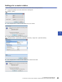
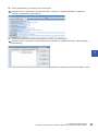
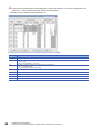
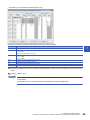
Settings for a master station . . . . . . . . . . . . . . . . . . . . . . . . . . . . . . . . . . . . . . . . . . . . . . . . . . . . . . . . . . . . . . . . 45
Settings for a remote device station . . . . . . . . . . . . . . . . . . . . . . . . . . . . . . . . . . . . . . . . . . . . . . . . . . . . . . . . . . 50
Checking the data link status. . . . . . . . . . . . . . . . . . . . . . . . . . . . . . . . . . . . . . . . . . . . . . . . . . . . . . . . . . . . . . . . 51
Program example . . . . . . . . . . . . . . . . . . . . . . . . . . . . . . . . . . . . . . . . . . . . . . . . . . . . . . . . . . . . . . . . . . . . . . . . 52
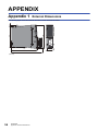
APPENDIX
56
Appendix 1 External Dimensions . . . . . . . . . . . . . . . . . . . . . . . . . . . . . . . . . . . . . . . . . . . . . . . . . . . . . . . . . . . . . . . . 56
INDEX
58
REVISIONS. . . . . . . . . . . . . . . . . . . . . . . . . . . . . . . . . . . . . . . . . . . . . . . . . . . . . . . . . . . . . . . . . . . . . . . . . . . . . .60
WARRANTY . . . . . . . . . . . . . . . . . . . . . . . . . . . . . . . . . . . . . . . . . . . . . . . . . . . . . . . . . . . . . . . . . . . . . . . . . . . . .61
TRADEMARKS . . . . . . . . . . . . . . . . . . . . . . . . . . . . . . . . . . . . . . . . . . . . . . . . . . . . . . . . . . . . . . . . . . . . . . . . . . .62
11
RELEVANT MANUALS
Manual name [manual number]
Description
Available form
MELSEC iQ-R CC-Link System Master/Local Module User's
Manual (Startup)
[SH-081269ENG] (this manual)
Specifications, procedures before operation, system configuration,
wiring, and communication examples of the CC-Link system
master/local module
Print book
MELSEC iQ-R CC-Link System Master/Local Module User's
Manual (Application)
[SH-081270ENG]
Functions, parameter settings, programming, troubleshooting, I/O
signals, and buffer memory of the CC-Link system master/local
module
Print book
MELSEC iQ-R Programming Manual (Instructions, Standard
Functions/Function Blocks)
[SH-081266ENG]
Instructions for the CPU module, dedicated instructions for the
intelligent function modules, and standard functions/function
blocks
e-Manual
EPUB
PDF
e-Manual
EPUB
PDF
e-Manual
EPUB
PDF
This manual does not include detailed information on the following:
• General specifications
• Applicable CPU modules and the number of mountable modules
• Installation
For details, refer to the following.
MELSEC iQ-R Module Configuration Manual
This manual does not include information on the module function blocks.
For details, refer to the Function Block Reference for the module used.
e-Manual refers to the Mitsubishi FA electronic book manuals that can be browsed using a dedicated tool.
e-Manual has the following features:
• Required information can be cross-searched in multiple manuals.
• Other manuals can be accessed from the links in the manual.
• The hardware specifications of each part can be found from the product figures.
• Pages that users often browse can be bookmarked.
12
TERMS
Unless otherwise specified, this manual uses the following terms.
Term
Description
CPU module
A generic term for the MELSEC iQ-R series CPU module
RAS
The abbreviation for Reliability, Availability, and Serviceability. This term refers to usability of automated
equipment.
Ver.1-compatible slave station
A slave station that supports the remote net Ver.1 mode or remote device net Ver.1 mode
Ver.2-compatible slave station
A slave station that supports the remote net Ver.2 mode or remote device net Ver.2 mode
Intelligent function module
A module that has functions other than input and output, such as an A/D converter module and D/A
converter module
Intelligent device station
A station that exchanges I/O signals (bit data) and I/O data (word data) with another station by cyclic
transmission. This station responds to a transient transmission request from another station and also
issues a transient transmission request to another station.
Engineering tool
Another term for the software package for the MELSEC programmable controllers
Disconnection
A process of stopping data link if a data link error occurs
Global label
A label that is enabled for all program data when creating multiple program data in the project.
There are two types of global labels: module label that is automatically generated by GX Works3 and
label that can be created for the any of the specified devices.
Slave station
A generic term for a remote I/O station, remote device station, local station, intelligent device station,
and standby master station
Cyclic transmission
A function by which data are periodically exchanged among stations on the same system using link
devices
Dedicated instruction
An instruction for using functions of the module
Data link
A generic term for cyclic transmission and transient transmission
Device
A device (X, Y, M, D, or others) in a CPU module
Transient transmission
A function to read/write data of a programmable controller on another station by using the dedicated
instruction and test or monitor another station by using the engineering tool
Buffer memory
A memory in an intelligent function module, where data (such as setting values and monitoring values)
are stored.
When using the CPU module, the memory is indicated for storing data (such as setting values and
monitored values) of the Ethernet function and data used for data communication of the multiple CPU
function.
Return
A process of restarting data link when a station recovers from an error
Master/local module
The abbreviation for the RJ61BT11 CC-Link system master/local module
Master station
A station that controls the entire system. This station can perform cyclic transmission and transient
transmission with all stations. Only one master station can be used in a system.
Module label
A label that represents one of memory areas (I/O signals and buffer memory areas) specific to each
module in a given character string.
For the module used, GX Works3 automatically generates this label, which can be used as a global
label.
Label
A label that represents a device in a given character string
Remote I/O net mode
A mode used to perform high-speed communications in a system consisting of a master station and
remote I/O station(s) only
Remote I/O station
A station that exchanges I/O signals (bit data) with the master station by cyclic transmission This station
cannot perform transient transmission.
Remote station
A generic term for a remote I/O station and a remote device station
Remote output (RY)
Bit data output from the master station to a slave station (For some areas in a local station, data are
output in the opposite direction.)
Remote device station
A station that exchanges I/O signals (bit data) and I/O data (word data) with the master station by cyclic
transmission. This station cannot perform transient transmission.
Remote device net Ver.1 mode
A mode used to configure a system only with a master station and Ver.1-compatible remote stations.
More remote device stations can be connected compared to the remote net Ver.1 mode.
Remote device net Ver.2 mode
A mode used to configure a system only with remote stations containing master stations and Ver.2compatible remote stations or to add Ver.2-compatible remote stations in future (a system only with
master stations and Ver.1-compatible remote stations).
More remote device stations can be connected compared to the remote net Ver.2 mode.
Remote input (RX)
Bit data input from a slave station to the master station (For some areas in a local station, data are
output in the opposite direction.)
13
14
Term
Description
Remote net Ver.1 mode
A mode used to configure a system only with a master station and Ver.1-compatible slave station.
Data can be communicated with all stations (remote I/O station, remote device station, local station,
intelligent device station, and standby master station) in a CC-Link system.
Remote net Ver.2 mode
A mode used to configure a system containing master stations and Ver.2-compatible slave stations or to
add Ver.2-compatible slave stations in future.
Data can be communicated with all stations (remote I/O station, remote device station, local station,
intelligent device station, and standby master station) in a CC-Link system.
Compared to the remote net Ver.1 mode, the number of cyclic points per station is increased from 128
to 896 for RX/RY, and from 16 to 128 for RWr/RWw.
Remote register (RWr)
Word data input from a slave station to the master station (For some areas in a local station, data are
output in the opposite direction.)
Remote register (RWw)
Word data output from the master station to a slave station (For some areas in a local station, data are
output in the opposite direction.)
Link scan (link scan time)
Time required for all stations in a system to transmit data. The link scan time depends on data volume
and the number of transient transmission requests.
Link device
A device (RX, RY, RWr, RWw, SB, or SW) in a CC-Link module
Link special relay (SB)
Bit data that indicates the operating status and data link status of modules on the master and local
stations
Link special register (SW)
Word data that indicates the operating status and data link status of modules on the master and local
stations
Local station
A station that performs cyclic transmission and transient transmission with the master station and other
local stations.
1
PART NAMES
1
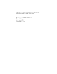
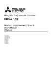
This section describes the part names of the master/local module.
(1)
(2)
(3)
(4)
No.
Name
Description
(1)
RUN LED
Indicates the operating status.
On: Normal operation
Off: A hardware error or a watchdog timer error has occurred.
ERR. LED
Indicates the error status of the module.
The details of errors can be checked by using the following.
• CC-Link diagnostics ( MELSEC iQ-R CC-Link System Master/Local Module User's Manual
(Application))
• 'Detailed LED display status' (SW0058) ( MELSEC iQ-R CC-Link System Master/Local Module User's
Manual (Application))
On: One of the following errors has occurred.
• The error on all the stations was detected.
• Two or more master stations are connected on the same line.
• Settings are incorrect.
• A cable is disconnected or a transmission path is affected by noise.
Flashing:A station with a data link error was detected. Or the station number set for a remote station is
already in use.
Off: Normal operation
MST LED
Indicates whether the module is operating as a master station.
On: Operating as a master station (during data link control)
Off: Operating as a local station or a standby master station (in standby status)
S MST LED
Indicates whether the module is operating as a standby master station.
On: Operating as a standby master station (in standby)
Off: Operating as a master station or a local station
B RATE LED
156K
625K
2.5M
Indicates the transmission speed that is normally operating.
On: Operating at the indicated transmission speed
All off:Transmission speed auto-tracking (When succeeded, the LED of the followed transmission speed
turns on.)
5M
10M
L RUN LED
Indicates the data link status.
On: Data link in progress
Off: Data link not performed
L ERR. LED
Indicates the error status of a data link.
On: A data link error has occurred at own station.
Flashing:The communications are unstable due to the following reasons.
• A terminating resistor is not connected.
• The communications are affected by noise.
Off: Normal operation
SD LED
Indicates whether the module is sending data.
On: Data being sent
Off: Data not sent
RD LED
Indicates whether the module is receiving data.
On: Data being received
Off: Data not received
1 PART NAMES
15
16
No.
Name
Description
(2)
Dot matrix LED
Displays the station number set in the module.
Indicates the following during the offline or test mode.
Offline: ""
Line test based on module parameter settings: "L.T."
Hardware test: "H.T."
(3)
Terminal block
Used to connect a Ver.1.10-compatible CC-Link dedicated cable. ( Page 32 WIRING)
The SLD and FG terminals are connected inside the module.
Because a two-piece terminal block is used, the module can be replaced without disconnecting the signal line
to the terminal block.
Before installing or removing the terminal block, power off the module.
(4)
Production information marking
Shows the product information (16 digits) of the module.
1 PART NAMES
2
SPECIFICATIONS
This chapter describes the specifications of the master/local module.
2.1
2
Performance Specifications
This section describes the performance specifications of the master/local module.
Item
Description
Transmission speed
Selected from 156kbps, 625kbps, 2.5Mbps, 5Mbps, and 10Mbps.
Maximum number of connectable
modules (master station)
64
Number of occupied stations (local
station)
1 to 4 stations (The number of stations can be changed using the engineering tool.)
Maximum number
of link points per
system
CC-Link Ver.1
• Remote I/O (RX, RY): 2048 points
• Remote register (RWw): 256 points (master station remote device station/local station/intelligent device
station/standby master station)
• Remote register (RWr): 256 points (remote device station/local station/intelligent device station/standby master
station master station)
CC-Link Ver.2
• Remote I/O (RX, RY): 8192 points
• Remote register (RWw): 2048 points (master station remote device station/local station/intelligent device
station/standby master station)
• Remote register (RWr): 2048 points (remote device station/local station/intelligent device station/standby master
station master station)
Number of link points per remote station/
local station/intelligent device station/
standby master station
Page 18 Number of link points by the number of occupied stations
Communication method
Broadcast polling method
Synchronization method
Frame synchronization method
Encoding method
NRZI method
Network topology
Bus (RS-485)
Transmission format
HDLC compliant
Error control system
CRC (X16 + X12 + X5 + 1)
Connection cable
Ver.1.10-compatible CC-Link dedicated cable
Maximum overall cable length (maximum
transmission distance)
Depends on the transmission speed ( Page 22 Maximum Overall Cable Length)
RAS function
•
•
•
•
Standby master station
Automatic return function
Slave station cutoff function
Error detection using link special relay areas (SB) and link special register areas (SW)
Number of occupied I/O points
32 points
Internal current consumption (5VDC)
0.34A
Weight
0.16kg
2 SPECIFICATIONS
2.1 Performance Specifications
17
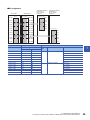
Number of link points by the number of occupied stations
The following table lists the number of link points by the number of occupied stations.
Item
CC-Link Ver.1
CC-Link Ver.2
Extended cyclic setting
Number of link
points by the
number of
occupied stations
1 station
occupied
2 stations
occupied
3 stations
occupied
4 stations
occupied
18
2 SPECIFICATIONS
2.1 Performance Specifications
Single
Double
Quadruple
Octuple
Remote I/O (RX,
RY)
32 points (30
points for a local
station)
32 points (30
points for a local
station)
32 points (30
points for a local
station)
64 points (62
points for a local
station)
128 points (126
points for a local
station)
Remote register
(RWw)
4 points
4 points
8 points
16 points
32 points
Remote register
(RWr)
4 points
4 points
8 points
16 points
32 points
Remote I/O (RX,
RY)
64 points (62
points for a local
station)
64 points (62
points for a local
station)
96 points (94
points for a local
station)
192 points (190
points for a local
station)
384 points (382
points for a local
station)
Remote register
(RWw)
8 points
8 points
16 points
32 points
64 points
Remote register
(RWr)
8 points
8 points
16 points
32 points
64 points
Remote I/O (RX,
RY)
96 points (94
points for a local
station)
96 points (94
points for a local
station)
160 points (158
points for a local
station)
320 points (318
points for a local
station)
640 points (638
points for a local
station)
Remote register
(RWw)
12 points
12 points
24 points
48 points
96 points
Remote register
(RWr)
12 points
12 points
24 points
48 points
96 points
Remote I/O (RX,
RY)
128 points (126
points for a local
station)
128 points (126
points for a local
station)
224 points (222
points for a local
station)
448 points (446
points for a local
station)
896 points (894
points for a local
station)
Remote register
(RWw)
16 points
16 points
32 points
64 points
128 points
Remote register
(RWr)
16 points
16 points
32 points
64 points
128 points
2.2
Maximum Number of Connectable Modules
A CC-Link system can be configured with the number of modules satisfying the following conditions.
Master station
2
Up to 26 modules
1 station in each system
Local station
Intelligent device station
Ver.1.10-compatible
CC-Link dedicated cable
Up to 64 modules
Up to 64 modules
Remote device station
Remote I/O station
Up to 64 modules
2 SPECIFICATIONS
2.2 Maximum Number of Connectable Modules
19
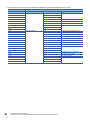
Remote net Ver.1 mode
The following table lists the maximum number of connectable modules of when a system is configured only with Ver.1compatible slave stations. For the modes, refer to the following.
Page 23 Modes
For one master station, 64 modules of a remote I/O station, remote device station, local station, standby master station, and
intelligent device station can be connected in total. Note, however, that the following conditions must be satisfied.
Item
Number of modules
Condition 1
{(1 a) + (2 b) + (3 c) + (4 d)} 64
a:
b:
c:
d:
Condition 2
{(16 A) + (54 B) + (88 C)} 2304
A: Number of remote I/O stations 64
B: Number of remote device stations 42
C: Number of local stations, standby master stations, and intelligent device
stations 26
Number of modules occupying 1 station
Number of modules occupying 2 stations
Number of modules occupying 3 stations
Number of modules occupying 4 stations
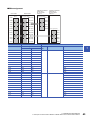
Remote net Ver.2 mode
The following table lists the maximum number of connectable modules of when a system is configured only with Ver.2compatible slave stations. For the modes, refer to the following.
Page 23 Modes
For one master station, 64 modules of a remote I/O station, remote device station, local station, standby master station, and
intelligent device station can be connected in total. Note, however, that the following conditions must be satisfied.
Item
20
Number of modules
Condition 1
{(a + a2 + a4 + a8)
+ (b + b2 + b4 + b8) 2
+ (c + c2 + c4 + c8) 3
+ (d + d2 + d4 + d8) 4} 64
Condition 2
[{(a 32) + (a2 32) + (a4 64) + (a8 128)}
+ {(b 64) + (b2 96) + (b4 192) + (b8 384)}
+ {(c 96) + (c2 160) + (c4 320) + (c8 640)}
+ {(d 128) + (d2 224) + (d4 448) + (d8 896)}] 8192
Condition 3
[{(a 4) + (a2 8) + (a4 16) + (a8 32)}
+ {(b 8) + (b2 16) + (b4 32) + (b8 64)}
+ {(c 12) + (c2 24) + (c4 48) + (c8 96)}
+ {(d 16) + (d2 32) + (d4 64) + (d8 128)}] 2048
Condition 4
{(16 A) + (54 B) + (88 C)} 2304
2 SPECIFICATIONS
2.2 Maximum Number of Connectable Modules
a: Total number of Ver.1-compatible slave stations occupying 1 station and Ver.2compatible slave stations occupying 1 station (extended cyclic setting: single)
b: Total number of Ver.1-compatible slave stations occupying 2 stations and Ver.2compatible slave stations occupying 2 stations (extended cyclic setting: single)
c: Total number of Ver.1-compatible slave stations occupying 3 stations and Ver.2compatible slave stations occupying 3 stations (extended cyclic setting: single)
d: Total number of Ver.1-compatible slave stations occupying 4 stations and Ver.2compatible slave stations occupying 4 stations (extended cyclic setting: single)
a2: Number of Ver.2-compatible slave stations occupying 1 station (extended cyclic
setting: double)
b2: Number of Ver.2-compatible slave stations occupying 2 stations (extended
cyclic setting: double)
c2: Number of Ver.2-compatible slave stations occupying 3 stations (extended
cyclic setting: double)
d2: Number of Ver.2-compatible slave stations occupying 4 stations (extended
cyclic setting: double)
a4: Number of Ver.2-compatible slave stations occupying 1 station (extended cyclic
setting: quadruple)
b4: Number of Ver.2-compatible slave stations occupying 2 stations (extended
cyclic setting: quadruple)
c4: Number of Ver.2-compatible slave stations occupying 3 stations (extended
cyclic setting: quadruple)
d4: Number of Ver.2-compatible slave stations occupying 4 stations (extended
cyclic setting: quadruple)
a8: Number of Ver.2-compatible slave stations occupying 1 station (extended cyclic
setting: octuple)
b8: Number of Ver.2-compatible slave stations occupying 2 stations (extended
cyclic setting: octuple)
c8: Number of Ver.2-compatible slave stations occupying 3 stations (extended
cyclic setting: octuple)
d8: Number of Ver.2-compatible slave stations occupying 4 stations (extended
cyclic setting: octuple)
A: Number of remote I/O stations 64
B: Number of remote device stations 42
C: Number of local stations, standby master stations, and intelligent device
stations 26
Remote device net Ver.1 mode
The following table lists the maximum number of connectable modules for a system configured in the remote device net Ver.1
mode. For the modes, refer to the following.
Page 23 Modes
2
For one master station, 64 modules of a remote I/O station and remote device station can be connected in total. Note,
however, that the following conditions must be satisfied.
Item
Condition 1
Number of modules
{(1 a) + (2 b) + (3 c) + (4 d)} 64
a:
b:
c:
d:
Number of modules occupying 1 station
Number of modules occupying 2 stations
Number of modules occupying 3 stations
Number of modules occupying 4 stations
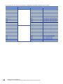
Remote device net Ver.2 mode
The following table lists the maximum number of connectable modules for a system configured in the remote device net Ver.2
mode. For the modes, refer to the following.
Page 23 Modes
For one master station, 64 modules of a remote I/O station and remote device station can be connected in total. Note,
however, that the following conditions must be satisfied.
Item
Number of modules
Condition 1
{(a + a2 + a4 + a8)
+ (b + b2 + b4 + b8) 2
+ (c + c2 + c4 + c8) 3
+ (d + d2 + d4 + d8) 4} 64
Condition 2
[{(a 32) + (a2 32) + (a4 64) + (a8 128)}
+ {(b 64) + (b2 96) + (b4 192) + (b8 384)}
+ {(c 96) + (c2 160) + (c4 320) + (c8 640)}
+ {(d 128) + (d2 224) + (d4 448) + (d8 896)}] 8192
Condition 3
[{(a 4) + (a2 8) + (a4 16) + (a8 32)}
+ {(b 8) + (b2 16) + (b4 32) + (b8 64)}
+ {(c 12) + (c2 24) + (c4 48) + (c8 96)}
+ {(d 16) + (d2 32) + (d4 64) + (d8 128)}] 2048
a: Total number of Ver.1-compatible remote stations occupying 1 station and
Ver.2-compatible remote device stations occupying 1 station (extended cyclic
setting: single)
b: Total number of Ver.1-compatible remote stations occupying 2 stations and
Ver.2-compatible remote device stations occupying 2 stations (extended cyclic
setting: single)
c: Total number of Ver.1-compatible remote stations occupying 3 stations and
Ver.2-compatible remote device stations occupying 3 stations (extended cyclic
setting: single)
d: Total number of Ver.1-compatible remote stations occupying 4 stations and
Ver.2-compatible remote device stations occupying 4 stations (extended cyclic
setting: single)
a2: Number of Ver.2-compatible remote device stations occupying 1 station
(extended cyclic setting: double)
b2: Number of Ver.2-compatible remote device stations occupying 2 stations
(extended cyclic setting: double)
c2: Number of Ver.2-compatible remote device stations occupying 3 stations
(extended cyclic setting: double)
d2: Number of Ver.2-compatible remote device stations occupying 4 stations
(extended cyclic setting: double)
a4: Number of Ver.2-compatible remote device stations occupying 1 station
(extended cyclic setting: quadruple)
b4: Number of Ver.2-compatible remote device stations occupying 2 stations
(extended cyclic setting: quadruple)
c4: Number of Ver.2-compatible remote device stations occupying 3 stations
(extended cyclic setting: quadruple)
d4: Number of Ver.2-compatible remote device stations occupying 4 stations
(extended cyclic setting: quadruple)
a8: Number of Ver.2-compatible remote device stations occupying 1 station
(extended cyclic setting: octuple)
b8: Number of Ver.2-compatible remote device stations occupying 2 stations
(extended cyclic setting: octuple)
c8: Number of Ver.2-compatible remote device stations occupying 3 stations
(extended cyclic setting: octuple)
d8: Number of Ver.2-compatible remote device stations occupying 4 stations
(extended cyclic setting: octuple)
Remote I/O net mode
The maximum number of connectable modules for a system configured in the remote I/O net mode is 64 stations. For the
modes, refer to the following.
Page 23 Modes
2 SPECIFICATIONS
2.2 Maximum Number of Connectable Modules
21
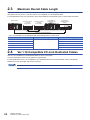
2.3
Maximum Overall Cable Length
This section describes how transmission speed and a maximum overall cable length are related when a system is configured
with products of CC-Link Ver.1.10 or later and Ver.1.10-compatible CC-Link dedicated cables.
For the identification of the CC-Link Version, refer to the installation manual issued by the CC-Link Partner Association.
Master station
Remote I/O station
or remote
device station
Remote I/O station
or remote
device station
Local station or
intelligent device
station
Local station or
intelligent device
station
Station-to-station cable length
Maximum overall cable distance
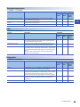
• Ver.1.10-compatible CC-Link dedicated cable (a terminating resistor of 110 used)
Transmission speed
Station-to-station cable length
156kbps
20cm or more
Maximum overall cable length
1200m
625kbps
900m
2.5Mbps
400m
5Mbps
160m
10Mbps
100m
2.4
Ver.1.10-Compatible CC-Link Dedicated Cables
Use Ver.1.10-compatible CC-Link dedicated cables for the CC-Link system.
If not, the performance of the CC-Link system is not guaranteed.
For the specifications of Ver.1.10 compatible CC-Link dedicated cables and contact information, refer to the following.
Website of CC-Link Association: http://www.cc-link.org/
For details, refer to the CC-Link Cable Wiring Manual issued by CC-Link Partner Association.
22
2 SPECIFICATIONS
2.3 Maximum Overall Cable Length
2.5
Modes
Select the mode according to the system used for the master/local module. Depending on the mode, the addresses of storage
positions for RX, RY, RWr, and RWw differ.
2
List of modes
Mode
Application
Connectable slave station
Remote net Ver.1 mode
To configure a new system (only with Ver.1-compatible slave stations)
Ver.1-compatible slave station
Remote net Ver.2 mode
• To configure a system including a Ver.2-compatible slave station
• More points are used compared to the remote net Ver.1 mode.
Ver.1-compatible slave station
and Ver.2-compatible slave
station
Remote device net Ver.1 mode*1
• To configure a system only with Ver.1-compatible remote stations
• More remote device stations are used compared to the remote net Ver.1
mode.
Ver.1-compatible remote station
Remote device net Ver.2 mode*1
• To configure a system only with remote stations containing Ver.2-compatible
remote stations
• More remote device stations are used compared to the remote net Ver.2
mode.
Ver.1-compatible remote station
and Ver.2-compatible remote
station
Remote I/O net mode*1
*1
To configure a system only with remote I/O stations
Remote I/O station
This mode cannot be selected when "Station Type" under "Required Settings" is set to something other than "Master Station".
For details on modes, refer to the following.
MELSEC iQ-R CC-Link System Master/Local Module User's Manual (Application)
2 SPECIFICATIONS
2.5 Modes
23
3
FUNCTION LIST
Cyclic transmission
This section describes the functions of the CC-Link system. For details on the functions, refer to the following.
MELSEC iQ-R CC-Link System Master/Local Module User's Manual (Application)
: Available, : Not available
Function
Communic
ations with
other
stations
Mode
Description
Communications using
RX and RY
Communicates I/O data in units of bits between the master station and
other stations.
Communications using
RWr and RWw
Communicates I/O data in units of words between the master station and
other stations.
Remote net Ver.1 mode
The mode can be selected according to the CC-Link system configuration.
Availability
Master
station
Local
station
Standby
master
station
Remote net Ver.2 mode
Remote device net Ver.1
mode
Remote device net Ver.2
mode
Remote I/O net mode
Automatically transfers data between the link device of the master/local
module and the device of the CPU module.
Cyclic data integrity assurance
Prevents read/write data from being separated between new and old data.
Sequence scan synchronization
specification
Selects whether link scan is set to asynchronous or synchronous with the
sequence scan of the CPU module.
Setting of the input data from a data
link faulty station
Selects whether I/O data from a station where a data link error occurs is
cleared or held.
Output data setting for CPU STOP
Selects whether remote output (RY) is refreshed (held at the value before
STOP) or cleared to zero (0) when the CPU module is set to STOP.
Data link setting when CPU is down
Selects whether data link is stopped or continued when a stop error occurs
in the CPU module which a master/local module is mounted with.
Data link stop and restart
Stops data link during debugging and other operations. (Data sending from
the own station is stopped.) Also, the stopped data link is restarted.
Remote I/O station points setting
Selects the number of refresh points with a remote I/O station from 8 points,
16 points, and 32 points when the master station is in the remote net Ver.2
mode or remote device net Ver.2 mode. Changing the number of points can
save the areas of the refresh device in a CPU module. (In modes other than
the remote net Ver.2 mode and remote device net Ver.2 mode, only 32
points per station can be selected.)
Link refresh
24
3 FUNCTION LIST
Transient transmission
: Available, : Not available
Function
Description
Availability
Master
station
Local
station
Standby
master
station
Communications in the same system
Performs the transient transmission to other stations using dedicated
instructions and the engineering tool.
Communications with different
networks
Performs the transient transmission seamlessly to stations on different
networks using the engineering tool.
Dedicated instruction
An instruction for using functions of modules.
Description
Availability
Master
station
Local
station
Standby
master
station
3
RAS
: Available, : Not available
Function
Slave station cutoff function
Disconnects only the slave station where an error occurs from the system,
and continues the data link with the stations that are operating normally.
(No module parameter setting is required.)
Automatic return function
Automatically returns the station disconnected from the system due to a
data link error to the system when it recovers and restarts data link.
Standby master function
Allows the standby master station to control slave stations instead of the
master station when the master station is disconnected in a system where
the master station and standby master station are connected on the same
system.
Using this function prevents the entire system from going down due to
disconnection of the master station.
Description
Availability
Master
station
Local
station
Standby
master
station
Diagnostics
: Available, : Not available
Function
Line test
Checks whether a Ver.1.10-compatible CC-Link dedicated cable is properly
connected and data link can be performed with slave stations.
Check of transmission speed setting
Checks whether the transmission speed setting of a slave station is the
same as that of the master station. The station number of the slave station
having a different transmission speed setting can be also checked;
therefore, corrective action upon a transmission error can be easily taken.
CC-Link diagnostics
Checks the status of CC-Link system using the engineering tool. The error
locations, error causes, and corrective actions can be checked in the
engineering tool.
Hardware test
Checks the hardware in the master/local module.
3 FUNCTION LIST
25
Others
: Available, : Not available
Function
26
Description
Availability
Master
station
Local
station
Standby
master
station
Reserved station function
Prevents slave stations that are not actually connected (but will be
connected in future) from detecting as "Data Link Faulty Station" in the
master station and local station. By setting slave stations that will be
connected in future as reserved stations, slave stations can be added
without a program change because the RX, RY, RWr, or RWw assignment
is not changed. In addition, the number of points of a slave station that has
been set as a reserved station can be set to zero points.
Error invalid station setting function
Prevents a slave station from being detected as a faulty station in the
master station and local station even if a data link error occurs in the slave
station. This function is used when a slave station is powered off as a
matter of the system configuration or for other purposes.
Temporary error invalid station setting
function
Prevents a slave station from being detected as a faulty station in the
master station and local station even if a data link error occurs in the slave
station. This setting can be configured even during data link, unlike the error
invalid station setting function. This function is used to exchange slave
stations for maintenance or for other purposes during data link.
Interrupt setting function
Issues an interrupt request to a CPU module when the interrupt conditions
that have been set using an engineering tool are satisfied, and executes the
interrupt program. This function is used to stop the control and execute an
interrupt program upon an error or for other purposes.
Remote device station initial setting
procedure registration function
Registers in advance the initial setting of a remote device station which is
performed on a program using an engineering tool and saves the setting by
turning on the link special relay (SB). A program for the initial setting is not
required.
Master station duplication error
canceling function
Clears a master station duplication error without resetting the CPU module
or powering off and on the system when the error has been detected.
Transmission speed auto-tracking
function on local stations
Automatically tracks the transmission speed of the master station when the
own station is a local station or standby master station. This function
eliminates transmission speed setting errors.
3 FUNCTION LIST
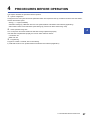
4
PROCEDURES BEFORE OPERATION
This chapter describes the procedures before operation.
1.
System configuration
Configure the CC-Link system and set the parameters which are required for start-up, the station number for the slave station,
and the transmission speed.
• Wiring ( Page 32 WIRING)
• Parameter settings ( MELSEC iQ-R CC-Link System Master/Local Module User's Manual (Application))
• Slave station number and transmission speed settings ( manual for slave station being used)
2.
4
Check operation using LED
Turn on the power and check whether the data link is being implemented properly.
If the data link is implemented properly, the LED On status will be as follows.
• L RUN LED: On
• ERR. LED: Off
3.
Programming
Program is created. For details, refer to the following.
MELSEC iQ-R CC-Link System Master/Local Module User's Manual (Application)
4 PROCEDURES BEFORE OPERATION
27
MEMO
28
4 PROCEDURES BEFORE OPERATION
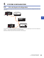
5
SYSTEM CONFIGURATION
5.1
CC-Link System Configuration
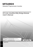
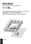
A CC-Link system is configured with a master station, remote I/O station, remote device station, intelligent device station, and
local station.
Master station
Remote I/O station
Terminating
resistor
5
Remote device station
Local station
Intelligent device station
Terminating
resistor
The CC-Link version and the number of slave stations that can be connected vary depending on the mode of the master/local
module. ( Page 19 Maximum Number of Connectable Modules)
Master/local modules of other series can be also used in a CC-Link system.
5 SYSTEM CONFIGURATION
5.1 CC-Link System Configuration
29
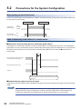
5.2
Precautions for the System Configuration
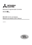
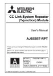
Please consider the following for system design to prevent incorrect input from a remote station.
When turning on and off the power
Power on the remote station, then start data link. In addition, stop data link before turning off the remote station. Failure to do
so may cause an incorrect input.
Data link starts.
Data link stops.
During
execution
Master station
(data link status)
Stopped
ON
Remote station
(power supply status)
OFF
Upon a momentary power failure of a remote station
If a momentary power failure occurs in the power supply (24VDC) of the remote station, an incorrect input may occur.
■Cause of an incorrect input due to a momentary power failure
The hardware of a remote station internally converts the power supply of a module (24VDC) into 5VDC. If an instantaneous
power failure occurs at a remote station, (the time until the 5VDC power supply in the remote station turns off) > (the response
time after an input module turns on and off); therefore, refreshing data within the time as shown in below causes an
incorrect input.
Ò
Remote station (module power supply
and input external power supply)
Remote station (internal 5VDC)
Input (Xn)
Turning off the input external power supply turns off an input (Xn)
after the response time between the input module turning on and
it turning off.
■Countermeasure against an incorrect input
Supply power to the power supply module, stabilized power supply, and AC input external power supply from the same power
supply.
When supplying power to multiple remote stations from one power supply, select applicable cables and
properly wire them to prevent a voltage drop caused by the power supply. When a remote station has a
receiving end voltage within the specified range for the remote station used, it can be connected.
30
5 SYSTEM CONFIGURATION
5.2 Precautions for the System Configuration
Access to a station with the station number 64
■Access from other stations using an engineering tool and GOT
Access to a local station with the station number 64 cannot be performed from other stations. Changing the station number to
the one other than 64 allows access from other stations.
■Access to other stations using a CC-Link system mater/local interface board
Access to a local station and intelligent device station with the station number 64 cannot be performed from other stations.
Changing the station number to the one other than 64 allows access from other stations.
5
5 SYSTEM CONFIGURATION
5.2 Precautions for the System Configuration
31
6
WIRING
This chapter describes the specifications of the master/local module wiring.
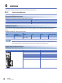
6.1
Terminal Block
Screws and tightening torque
Tighten the terminal block screws within the specified torque range.
Screw type
Tightening torque range
Terminal block screw (M3 screw)
0.42 to 0.58Nm
Terminal block mounting screw (M3.5 screw)
0.66 to 0.89Nm
Solderless terminal
Use a solderless terminal and wire specified in the following table. Tighten a solderless terminal within the specified torque
range. Use a UL certified solderless terminal and use a tool recommended by the solderless terminal manufacturer for
forming.
Solderless terminals with sleeves cannot be used.
Solderless terminal
Wire
Model
Applicable
tightening torque
Diameter
Type
Material
Temperature rating
R1.25-3
0.42 to 0.58Nm
0.3 to 1.25
(22 to 16 AWG)
Stranded
Copper
60 or more
Solderless terminals with insulation sleeves cannot be used for the terminal block. It is recommended to cover
the connecting sections of the solderless terminals with a marking tube or insulation tube.
Signal name for terminal block
Shows the signal name for the terminal block
Terminal block
32
6 WIRING
6.1 Terminal Block
Terminal number
Signal name
1
NC
2
NC
3
DA
4
SLD
5
DB
6
FG
7
DG
6.2
Wiring Procedure
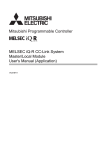
Wiring to terminal block
Shows wiring to the terminal block.
(Blue)
Terminating
resistor
(White)
(Yellow)
• Connect the terminating resistors between the DA and DB terminals.
6
• Connect the shield wires of a Ver.1.10 compatible CC-Link dedicated cable to the SLD terminal through the
FG terminal. Then ground the cables at both ends with a ground resistance of 100 ohms or less. The SLD
and FG terminals are connected inside.
• For the terminal processing of when connecting the Ver.1.10-compatible CC-Link dedicated cable to the
terminal block, do not unfasten the DA/DB/DG cable (three wires in one cable) or remove the sheath more
than necessary. (For cables with fillers, cut them using a tool.)
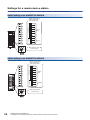
Wiring example
Terminating
resistor
DA
DB
DG
SLD
(Blue)
(Blue)
(White)
(White)
(Yellow)
(Yellow)
Ver.1.10-compatible
CC-Link dedicated cable
FG
DA
DB
DG
SLD
(Blue)
(Blue)
(White)
(White)
(Yellow)
(Yellow)
Ver.1.10-compatible
CC-Link dedicated cable
FG
DA
DB
Terminating
resistor
DG
SLD
FG
• No restrictions apply to the connection order of a master/local module. (The cables need not be connected
in the order of station number.)
• The star topology cannot be used. Note, however, that the T-branch connection can be used. ( Page 34
T-branch Connection)
6.3
Product for Wiring
Cables that can be used
Use Ver.1.10 compatible CC-Link dedicated cables.
Note, the cables need not be connected in the order of station number.
Terminating resistor to be used
Connect the terminating resistors included with the modules at both ends of the modules in the CC-Link system.
6 WIRING
6.2 Wiring Procedure
33
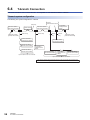
6.4
T-branch Connection
This section describes how to connect the Ver.1.10 compatible CC-Link dedicated cables in T-branch.
T-branch system configuration
The following is a system configuration in T-branch.
T-branch
terminal block/connector
(Main line)
Remote I/O station/
Remote device station
Terminating resistor
[between DA and DB]
(Branch line)
(Branch line)
Remote I/O station/
Remote device station
Remote I/O station/
Remote device station
Local station/
Intelligent device
station
Remote I/O station/
Remote device station
Master station
(Branch
line)
(Branch
line)
Terminating resistor
[between DA and DB]
Remote I/O station/
Remote device station
Local station/
Intelligent device
station
Remote I/O station/
Remote device station
Up to six stations can be connected.
Remote I/O station/
Remote device station
Local station/
Intelligent device
station
Remote I/O station/
Remote device station
Up to six stations can be connected.
The number of branch lines is determined by the branch line length per branch line and
the overall branch line length.
34
6 WIRING
6.4 T-branch Connection
Communication specifications for a T-branch connection
The following table lists the communication specifications upon T-branch connection.
For those not listed below, refer to the performance specifications. ( Page 17 Performance Specifications)
Item
Specifications
Transmission speed
625kbps
156kbps
Remarks
10M, 5M, and 2.5Mbps cannot be
used.
Maximum length of the main line
100m
500m
A cable length between terminating
resistors.
The length (branch line length) of a Tbranch cable is not included.
Maximum length of the branch line
8m
Overall branch line length
50m
Maximum number of connected
modules on the branch line
6 stations per branch
The total number of connected
stations depends on the CC-Link
specifications.
Connection cable
Ver.1.10-compatible CC-Link dedicated cable
T branch terminal block
Commercially available terminal block
T branch connector
A connector for an FA sensor conforming to NECA4202 (IEC947-5-2) or
equivalent product is recommended.
(NECA: Nippon Electric Control Equipment Industries Association)
Do not remove the jacket of the
cables on the branch line, if possible.
A total cable length for each branch
200m
A total length of all branch cables
6
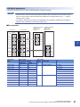
■Maximum length of the main line, distance between T-branches, and cable length between
stations
Transmission
speed
Maximum
length of the
main line
Distance
between T
branches
Station-to-station cable length
between remote I/O stations or
remote device stations
Station-to-station cable length between a
master station, local station, or intelligent
device station and an adjacent station to the
front or back
625kbps
100m
No restriction
30cm or more
1m or more *1/2m or more*2
156kbps
500m
*1
*2
This applies to a system configuration with a remote I/O station and remote device station.
This applies to a system configuration including a local station and intelligent device station.
Maximum length of the main line (not including the branch line length)
Terminating
resistor
*4
*4
R
*3
R
Master station
*3
R
Terminating
resistor
Distance between T branches
*4
*4
R
*4
*4
L/I
L/I
R
*4
*4
*4
R
*3
L/I
L/I
*3
R
*3
R
*3
R
*3
R
R
R
(Branch line length: 8m or shorter)
*3
R
: Represents a remote I/O station or a remote device station.
R
(Branch line length: 8m or shorter)
*3
*4
L/I : Represents a local station or an intelligent device station.
Station-to-station cable length between remote I/O stations or remote device stations
Station-to-station cable length between a master/ local station, or intelligent device station and an adjacent station to the front or back
6 WIRING
6.4 T-branch Connection
35
7
COMMUNICATION EXAMPLES
This chapter describes programming and start-up examples of the master/local module.
7.1
Example of Communications Between a Master
Station and a Remote Device Station
This section describes an example of how to set the initial settings for the remote device station and perform an analog input
and analog output.
If an error occurs, the error code of the remote device station is stored in the device of a CPU module or the module label.
System configuration example
The following system configuration is used to explain communication between the master station and remote device station.
System configuration
Master station
(remote net Ver.1 mode)
Module name
Start I/O No.
R04CPU
RJ61BT11
RX10
RY10R2
X/Y00 to X/Y1F
X20 to X2F
Y30 to Y3F
Terminating resistor
Terminating resistor
AJ65VBTCU-68ADVN
AJ65VBTCU-68DAVN
Ver.1 compatible remote device station
(station No.1)
Number of occupied
stations: 3
36
Ver.1 compatible remote device station
(station No.4)
Number of occupied
stations: 3
7 COMMUNICATION EXAMPLES
7.1 Example of Communications Between a Master Station and a Remote Device Station
Link device assignment
This section describes the RX, RY, RWr, or RWw assignment of program examples.
• Remote net Ver.1 mode is used in this program examples. When the remote net Ver.2 mode or remote
device net Ver.2 mode is used, the buffer memory addresses of storage locations vary. ( Page 20
Remote net Ver.1 mode)
• For details on the signals of the RX/RY and RWr/RWw of the AJ65VBTCU-68ADVN and AJ65VBTCU68DAVN, refer to the manual for the remote station used.
■RX assignment
CPU module
Device
Master station
Buffer memory
(remote input (RX))
X1000
·
X101F
X1020
·
X103F
X1040
·
X105F
Station
No.1
Station
No.1
AJ65VBTCU-68DAVN
(Station No.4)
No. of occupied
stations: 3
Remote input (RX)
E0H (224)
·
E1H (225)
E2H (226)
·
E3H (227)
E4H (228)
·
E5H (229)
Station
No.1
RX00
·
RX1F
RX20
·
RX3F
RX40
·
RX5F
Station
No.4
Station
No.4
E8H (232)
·
E9H (233)
Station
No.4
EAH (234)
·
EBH (235)
X10A0
·
X10BF
7
Remote input (RX)
E6H (230)
·
E7H (231)
X1060
·
X107F
X1080
·
X109F
AJ65VBTCU-68ADVN
(Station No.1)
No. of occupied
stations: 3
RX00
·
RX1F
RX20
·
RX3F
RX40
·
RX5F
CPU module
Master station
Slave station
Device
Buffer memory address
Module name
RX
Hexadecimal
Decimal
Station
No.
X1000 to X100F
E0H
224
1
AJ65VBTCU-68ADVN
RX0 to RXF
X1010 to X101F
E1H
225
RX10 to RX1F
X1020 to X102F
E2H
226
RX20 to RX2F
X1030 to X103F
E3H
227
RX30 to RX3F
X1040 to X104F
E4H
228
RX40 to RX4F
X1050 to X105F
E5H
229
RX50 to RX5F
X1060 to X106F
E6H
230
X1070 to X107F
E7H
231
RX10 to RX1F
X1080 to X108F
E8H
232
RX20 to RX2F
X1090 to X109F
E9H
233
RX30 to RX3F
X10A0 to X10AF
EAH
234
RX40 to RX4F
X10B0 to X10BF
EBH
235
RX50 to RX5F
4
AJ65VBTCU-68DAVN
RX0 to RXF
7 COMMUNICATION EXAMPLES
7.1 Example of Communications Between a Master Station and a Remote Device Station
37
The assignment by each signal of the AJ65VBTCU-68ADVN and AJ65VBTCU-68DAVN are shown below.
CPU module
Remote station
Device
Module name
RX
Signal name
X1000
AJ65VBTCU-68ADVN
RX00
CH.1 A/D conversion completion flag
X1001
RX01
CH.2 A/D conversion completion flag
X1002
RX02
CH.3 A/D conversion completion flag
X1003
RX03
CH.4 A/D conversion completion flag
X1004
RX04
CH.5 A/D conversion completion flag
X1005
RX05
CH.6 A/D conversion completion flag
X1006
RX06
CH.7 A/D conversion completion flag
X1007
RX07
CH.8 A/D conversion completion flag
X1008
RX08
Use prohibited
to
to
X100B
RX0B
X100C
RX0C
E2PROM write error flag
X100D
RX0D
Use prohibited
to
to
X1017
RX17
X1018
RX18
Initial data processing request flag
X1019
RX19
Initial data setting completion flag
X101A
RX1A
Error status flag
X101B
RX1B
Remote READY
X101C
RX1C
Use prohibited
to
to
X105F
X1060
38
RX5F
AJ65VBTCU-68DAVN
RX00
Use prohibited
to
to
X106B
RX0B
X106C
RX0C
E2PROM write error flag
X106D
RX0D
Use prohibited
to
to
X1077
RX17
X1078
RX18
Initial data processing request flag
X1079
RX19
Initial data setting completion flag
X107A
RX1A
Error status flag
X107B
RX1B
Remote READY
X107C
RX1C
Use prohibited
to
to
X10BF
RX5F
7 COMMUNICATION EXAMPLES
7.1 Example of Communications Between a Master Station and a Remote Device Station
■RY assignment
CPU module
Device
Master station
Buffer memory
(remote output (RY))
Y1000
·
Y101F
Y1020
·
Y103F
Y1040
·
AJ65VBTCU-68ADVN
(Station No.1)
No. of occupied
stations: 3
Remote output (RY)
160H (352)
·
161H (353)
Y105F
162H (354)
·
163H (355)
164H (356)
·
165H (357)
Y1060
·
Y107F
166H (358)
·
167H (359)
Y1080
·
Y109F
Station
No.1
Station
No.4
Station
No.1
Station
No.4
AJ65VBTCU-68DAVN
(Station No.4)
No. of occupied
stations: 3
Station
No.1
RY00
·
RY1F
RY20
·
RY3F
RY40
·
RY5F
Remote output (RY)
168H (360)
·
169H (361)
Station
No.4
16AH (362)
·
16BH (363)
Y10A0
·
Y10BF
RY00
·
RY1F
RY20
·
RY3F
RY40
·
RY5F
CPU module
Master station
Slave station
Device
Buffer memory address
Station
No.
Module name
1
AJ65VBTCU-68ADVN
Hexadecimal
Decimal
Y1000 to Y100F
160H
352
Y1010 to Y101F
161H
353
RY10 to RY1F
Y1020 to Y102F
162H
354
RY20 to RY2F
Y1030 to Y103F
163H
355
RY30 to RY3F
Y1040 to Y104F
164H
356
RY40 to RY4F
Y1050 to Y105F
165H
357
RY50 to RY5F
Y1060 to Y106F
166H
358
Y1070 to Y107F
167H
359
RY10 to RY1F
Y1080 to Y108F
168H
360
RY20 to RY2F
Y1090 to Y109F
169H
361
RY30 to RY3F
Y10A0 to Y10AF
16AH
362
RY40 to RY4F
Y10B0 to Y10BF
16BH
363
RY50 to RY5F
4
AJ65VBTCU-68DAVN
7
RY
RY0 to RYF
RY0 to RYF
7 COMMUNICATION EXAMPLES
7.1 Example of Communications Between a Master Station and a Remote Device Station
39
The assignment by each signal of the AJ65VBTCU-68ADVN and AJ65VBTCU-68DAVN are shown below.
CPU module
Remote station
Device
Module name
RY
Signal name
Y1000
AJ65VBTCU-68ADVN
RY00
Use prohibited
to
to
Y1017
RY17
Y1018
RY18
Initial data processing completion flag
Y1019
RY19
Initial data setting request flag
Y101A
RY1A
Error reset request flag
Y101B
RY1B
Use prohibited
to
to
Y105F
Y1060
40
RY5F
AJ65VBTCU-68DAVN
RY00
CH.1 analog output enable/disable flag
Y1061
RY01
CH.2 analog output enable/disable flag
Y1062
RY02
CH.3 analog output enable/disable flag
Y1063
RY03
CH.4 analog output enable/disable flag
Y1064
RY04
CH.5 analog output enable/disable flag
Y1065
RY05
CH.6 analog output enable/disable flag
Y1066
RY06
CH.7 analog output enable/disable flag
Y1067
RY07
CH.8 analog output enable/disable flag
Y1068
RY08
Use prohibited
to
to
Y1077
RY17
Y1078
RY18
Initial data processing completion flag
Y1079
RY19
Initial data setting request flag
Y107A
RY1A
Error reset request flag
Y107B
RY1B
Use prohibited
to
to
Y10BF
RY5F
7 COMMUNICATION EXAMPLES
7.1 Example of Communications Between a Master Station and a Remote Device Station
■RWr assignment
CPU module
Device
Master station
Buffer memory
(remote register (RWr))
W0
·
W3
W4
·
W7
W8
·
WB
Station
No.1
Station
No.1
AJ65VBTCU-68DAVN
(Station No.4)
No. of occupied
stations: 3
Remote register (RWr)
2E0H (736)
·
2E3H (739)
2E4H (740)
·
2E7H (743)
2E8H (744)
·
Station
No.1
RWr0
·
RWr3
RWr4
·
RWr7
RWr8
·
RWrB
2EBH (747)
Remote register (RWr)
2ECH (748)
·
2EFH (751)
WC
·
WF
W10
·
W13
AJ65VBTCU-68ADVN
(Station No.1)
No. of occupied
stations: 3
Station
No.4
Station
No.4
2F0H (752)
·
2F3H (755)
Station
No.4
2F4H (756)
·
2F7H (759)
W14
·
W17
RWr0
·
RWr3
RWr4
·
RWr7
RWr8
·
RWrB
CPU module
Master station
Slave station
Device
Buffer memory address
Station
No.
Module name
RWr
1
AJ65VBTCU-68ADVN
RWr0
Hexadecimal
Decimal
W0
2E0H
736
W1
2E1H
737
RWr1
W2
2E2H
738
RWr2
W3
2E3H
739
RWr3
W4
2E4H
740
RWr4
W5
2E5H
741
RWr5
W6
2E6H
742
RWr6
W7
2E7H
743
RWr7
W8
2E8H
744
RWr8
W9
2E9H
745
RWr9
WA
2EAH
746
RWrA
WB
2EBH
747
WC
2ECH
748
WD
2EDH
749
7
RWrB
4
AJ65VBTCU-68DAVN
RWr0
RWr1
WE
2EEH
750
RWr2
WF
2EFH
751
RWr3
W10
2F0H
752
RWr4
W11
2F1H
753
RWr5
W12
2F2H
754
RWr6
W13
2F3H
755
RWr7
W14
2F4H
756
RWr8
W15
2F5H
757
RWr9
W16
2F6H
758
RWrA
W17
2F7H
759
RWrB
7 COMMUNICATION EXAMPLES
7.1 Example of Communications Between a Master Station and a Remote Device Station
41
The assignment by each signal of the AJ65VBTCU-68ADVN and AJ65VBTCU-68DAVN are shown below.
CPU module
Remote station
Device
Module name
RWr
Signal name
W0
AJ65VBTCU-68ADVN
RWr0
CH.1 digital output value
W1
RWr1
CH.2 digital output value
W2
RWr2
CH.3 digital output value
W3
RWr3
CH.4 digital output value
W4
RWr4
CH.5 digital output value
W5
RWr5
CH.6 digital output value
W6
RWr6
CH.7 digital output value
W7
RWr7
CH.8 digital output value
W8
RWr8
Error code
W9
RWr9
Use prohibited
to
to
WB
RWrB
WC
42
AJ65VBTCU-68DAVN
RWr0
CH.1 check code
WD
RWr1
CH.2 check code
WE
RWr2
CH.3 check code
WF
RWr3
CH.4 check code
W10
RWr4
CH.5 check code
W11
RWr5
CH.6 check code
W12
RWr6
CH.7 check code
W13
RWr7
CH.8 check code
W14
RWr8
Error code
W15
RWr9
Use prohibited
to
to
W17
RWrB
7 COMMUNICATION EXAMPLES
7.1 Example of Communications Between a Master Station and a Remote Device Station
■RWw assignment
CPU module
Device
Master station
Buffer memory
(remote register (RWw))
W100
·
W103
W104
·
W107
W108
·
W10B
Station
No.1
Station
No.1
AJ65VBTCU-68DAVN
(Station No.4)
No. of occupied
stations: 3
Remote register (RWw)
1E0H (480)
·
1E3H (483)
1E4H (484)
·
1E7H (487)
1E8H (488)
·
1EBH (491)
Station
No.1
RWw0
·
RWw3
RWw4
·
RWw7
RWw8
·
RWwB
Remote register (RWw)
1ECH (492)
·
1EFH (495)
W10C
·
W10F
W110
·
W113
AJ65VBTCU-68ADVN
(Station No.1)
No. of occupied
stations: 3
Station
No.4
Station
No.4
1F0H (496)
·
1F3H (499)
Station
No.4
1F4H (500)
·
1F7H (503)
W114
·
W117
RWw0
·
RWw3
RWw4
·
RWw7
RWw8
·
RWwB
CPU module
Master station
Slave station
Device
Buffer memory address
Station
No.
Module name
RWw
1
AJ65VBTCU-68ADVN
RWw0
Hexadecimal
Decimal
W100
1E0H
480
W101
1E1H
481
RWw1
W102
1E2H
482
RWw2
W103
1E3H
483
RWw3
W104
1E4H
484
RWw4
W105
1E5H
485
RWw5
W106
1E6H
486
RWw6
W107
1E7H
487
RWw7
W108
1E8H
488
RWw8
W109
1E9H
489
RWw9
W10A
1EAH
490
RWwA
W10B
1EBH
491
RWwB
W10C
1ECH
492
W10D
1EDH
493
4
AJ65VBTCU-68DAVN
RWw1
W10E
1EEH
494
RWw2
W10F
1EFH
495
RWw3
W110
1F0H
496
RWw4
W111
1F1H
497
RWw5
W112
1F2H
498
RWw6
W113
1F3H
499
RWw7
W114
1F4H
500
RWw8
W115
1F5H
501
RWw9
W116
1F6H
502
RWwA
W117
1F7H
503
RWwB
7
RWw0
7 COMMUNICATION EXAMPLES
7.1 Example of Communications Between a Master Station and a Remote Device Station
43
The assignment by each signal of the AJ65VBTCU-68ADVN and AJ65VBTCU-68DAVN are shown below.
CPU module
Remote station
Device
Module name
RWw
Signal name
W100
AJ65VBTCU-68ADVN
RWw0
A/D conversion enable/prohibit specification
RWw1
CH.1 to 4 input range setting
W101
W102
RWw2
CH.5 to 8 input range setting
W103
RWw3
Average processing specification
W104
RWw4
CH.1 average time, number of times setting
W105
RWw5
CH.2 average time, number of times setting
W106
RWw6
CH.3 average time, number of times setting
W107
RWw7
CH.4 average time, number of times setting
W108
RWw8
CH.5 average time, number of times setting
W109
RWw9
CH.6 average time, number of times setting
W10A
RWwA
CH.7 average time, number of times setting
W10B
RWwB
CH.8 average time, number of times setting
RWw0
CH.1 digital value setting
W10D
RWw1
CH.2 digital value setting
W10E
RWw2
CH.3 digital value setting
W10F
RWw3
CH.4 digital value setting
W110
RWw4
CH.5 digital value setting
W111
RWw5
CH.6 digital value setting
W112
RWw6
CH.7 digital value setting
W113
RWw7
CH.8 digital value setting
W114
RWw8
Analog output enable/disable setting
W115
RWw9
CH.1 to 4 output range setting
W116
RWwA
CH.5 to 8 output range setting
W117
RWwB
HOLD/CLEAR setting
W10C
44
AJ65VBTCU-68DAVN
7 COMMUNICATION EXAMPLES
7.1 Example of Communications Between a Master Station and a Remote Device Station
Settings for a master station
Connect the engineering tool to the CPU module of the master station and set parameters.
1.
Configure the settings of the CPU module in the following item.
[Project] [New]
2.
Click the [Yes] button to add the module labels of the CPU module.
7
3.
Set the master/local module in the following item.
Navigation window [Parameter] [Module Information] Right-click [Add New Module]
4.
Click the [Yes] button to add the module labels of the master/local module.
7 COMMUNICATION EXAMPLES
7.1 Example of Communications Between a Master Station and a Remote Device Station
45
5.
Set the contents of "Required Settings" in the following item.
Navigation window [Parameter] [Module Information] [RJ61BT11] [Module Parameter] [Required Settings]
6.
Set the network configuration in the following item.
Navigation window [Parameter] [Module Information] [RJ61BT11] [Module Parameter] [Basic Settings]
[Network Configuration Settings]
7.
Set the link refresh settings in the following item.
Navigation window [Parameter] [Module Information] [RJ61BT11] [Module Parameter] [Basic Settings]
[Link Refresh Settings]
46
7 COMMUNICATION EXAMPLES
7.1 Example of Communications Between a Master Station and a Remote Device Station
8.
Set the "Supplementary Cyclic Settings" in the following item.
Navigation window [Parameter] [Module Information] [RJ61BT11] [Module Parameter] [Application
Settings] [Supplementary Cyclic Settings]
9.
Set the "Remote Device Initial Setting Target Station No. Setting" in the following item.
Navigation window [Parameter] [Module Information] [RJ61BT11] [Module Parameter] [Basic Settings]
[Initial Settings]
7
10. Double-click "No. of Registered Procedures" to open the "Remote Device Initial Setting Procedure Registration" window.
7 COMMUNICATION EXAMPLES
7.1 Example of Communications Between a Master Station and a Remote Device Station
47
11. In "Remote Device Initial Setting Procedure Registration" window, right-click the icon and click "Hexadecimal" of the
"Input Format". Set the contents of the initial settings in the following item.
• Initial setting for an AJ65VBTCU-68ADVN (station No.1)
Setting the initial setting executes the following processing from the first condition.
Condition
48
Description
1st
The CH.1 and CH.2 are set to the A/D conversion enable.
2nd
An input range is set.
• CH.1: 0 to 5V
• CH.2: User range setting 1 (-10 to 10V)
3rd
Whether a averaging processing or averaging process is executed is set.
• CH.1: Sampling processing
• CH.2: Averaging processing (count average)
4th
The average count of the CH.2 is set to 16.
5th
Initial data processing completion flag is turned on.
6th
Initial data setting request flag is turned on.
7th
Initial data processing completion flag is turned off.
8th
Initial data setting request flag is turned off.
7 COMMUNICATION EXAMPLES
7.1 Example of Communications Between a Master Station and a Remote Device Station
• Initial setting for an AJ65VBTCU-68DAVN (station No.4)
Setting the initial setting executes the following processing from the first condition.
Condition
Description
1st
The CH.1 and CH.2 are set to the analog output enable.
2nd
An output range is set.
• CH.1: 0 to 5V
• CH.2: User range setting 1 (-10 to 10V)
3rd
The HOLD/CLEAR setting is configured.
• CH.1: CLEAR
• CH.2: CLEAR
4th
Initial data processing completion flag is turned on.
5th
Initial data setting request flag is turned on.
6th
Initial data processing completion flag is turned off.
7th
Initial data setting request flag is turned off.
7
12. Write the set parameters to the CPU module on the master station. Then reset the CPU module or power off and on the
system.
[Online] [Write to PLC]
In this example, default values were used for parameters that are not shown above. For the parameters, refer
to the following.
MELSEC iQ-R CC-Link System Master/Local Module User's Manual (Application)
7 COMMUNICATION EXAMPLES
7.1 Example of Communications Between a Master Station and a Remote Device Station
49
Settings for a remote device station
Set the station number, transmission speed, and mode using the switches on the remote device station.
Switch setting on an AJ65VBTCU-68ADVN
40 OFF
20 OFF
10 OFF
B RATE
STATION NO.
1 place
10 place
Station number setting
switch, transmission
speed setting switch
8
OFF
4
OFF
2
OFF
1
ON
4
OFF
2
OFF
1
OFF
Station
No.1
156kbps
Mode selection switch
0 (normal mode)
Switch setting on an AJ65VBTCU-68DAVN
Station number setting
switch, transmission
speed setting switch
B RATE
STATION NO.
1 place
10 place
40 OFF
20 OFF
10 OFF
8
OFF
4
ON
2
OFF
1
OFF
4
OFF
2
OFF
1
OFF
Station
No.4
156kbps
Mode selection switch
0 (normal mode)
50
7 COMMUNICATION EXAMPLES
7.1 Example of Communications Between a Master Station and a Remote Device Station
Checking the data link status
Check whether the master station and remote device station are normally operating data link.
1.
2.
Power on the remote station, then master station to start data link.
When the LEDs are in the following states, data link is being performed normally.
• LEDs on the master station
LED
Status
RUN
On
ERR.
Off
MST
On
S MST
Off
156K
On
625K
Off
2.5M
5M
10M
L RUN
On
L ERR.
Off
SD
Flashing*1
RD
*1
7
The LEDs may look dimly lit or off depending on the communication status.
• LEDs on the AJ65VBTCU-68ADVN and AJ65VBTCU-68DAVN
: ON
: OFF
7 COMMUNICATION EXAMPLES
7.1 Example of Communications Between a Master Station and a Remote Device Station
51
Program example
• Master station (station No.0)
Classification
Module label
Label to be defined
52
Label name
Description
Device
X0
BT11_1.bIn_ModuleFailure
Module failure
BT11_1.bIn_DataLink
Own station data link status
X1
BT11_1.bIn_ModuleReady
Module ready
XF
BT11_1.bReq_RemoteDeviceStationInitialization
Remote device station initialization procedure registration
instruction
SB000D
BT11_1.bCompl_RemoteDeviceStationInitialization
Completion status of remote device station initialization
procedure
SB005F
BT11_1.bnSts_DataLinkError_Other[1]
Data link status of other stations (station No.1)
SW0080.0
BT11_1.bnSts_DataLinkError_Other[4]
Data link status of other stations (station No.4)
SW0080.3
Define global labels as shown below:
Device
Description
Module
X1000 to X105F
Remote input (RX0 to RX5F)
AJ65VBTCU-68ADVN
Y1000 to Y105F
Remote output (RY0 to RY5F)
W0 to WB
Remote register (RWr0 to RWrB)
W100 to W10B
Remote register (RWw0 to RWwB)
X1060 to X10BF
Remote input (RX0 to RX5F)
Y1060 to Y10BF
Remote output (RY0 to RY5F)
WC to W17
Remote register (RWr0 to RWrB)
W10C to W117
Remote register (RWw0 to RWwB)
7 COMMUNICATION EXAMPLES
7.1 Example of Communications Between a Master Station and a Remote Device Station
AJ65VBTCU-68DAVN
7
7 COMMUNICATION EXAMPLES
7.1 Example of Communications Between a Master Station and a Remote Device Station
53
(0)
The data link status is checked.
(26) When 'Remote device station initialization procedure registration instruction' (SB000D) is turned on, the initial setting is executed.
When the initial setting is completed, the input value of the AJ65VBTCU-68ADVN is converted into a digital value.
(30) When 'Initialization_68ADVN' (X20) is turned on, the initial setting of the AJ65VBTCU-68ADVN is changed.
(47) The CH.1 digital output value is stored in 'DigitalOutputValue_CH1_68ADVN' (D500) and CH.2 digital output value is stored in
'DigitalOutputValue_CH2_68ADVN' (D501).
(56) If an error occurs in the AJ65VBTCU-68ADVN, an error code is stored in 'ErrorCode_68DAVN' (D508).
After the cause of the error is eliminated and 'ResetError_68ADVN' (X25) is turned on, the error is reset.
(65) When 'Initialization_68DAVN' (X21) is turned on, the initial setting of the AJ65VBTCU-68DAVN is changed.
(76) When 'DigitalValue_68DAVN' (X22) is turned on, the digital value of the AJ65VBTCU-68DAVN is set.
(84) When 'EnableAnalogOutput_68DAVN' (X23) is turned on, the analog value is output from the AJ65VBTCU-68DAVN.
(88) If an error occurs in the AJ65VBTCU-68DAVN, an error code is stored in 'ErrorCode_68DAVN' (D518).
After the cause of the error is eliminated and 'ResetError_68DAVN' (X26) is turned on, the error is reset.
• When creating the programs of (19) to (26), refer to the manual for the remote device station used and
change the program as needed.
• The programs of (30) to (45) and (65) to (74) are needed only for the initial setting change.
54
7 COMMUNICATION EXAMPLES
7.1 Example of Communications Between a Master Station and a Remote Device Station
MEMO
7
7 COMMUNICATION EXAMPLES
7.1 Example of Communications Between a Master Station and a Remote Device Station
55
APPENDIX
Appendix 1
External Dimensions
98
106
4
The following figure shows the external dimensions of the master/local module.
110
27.8
131
(Unit: mm)
56
APPENDIX
Appendix 1 External Dimensions
MEMO
A
APPENDIX
Appendix 1 External Dimensions
57
INDEX
C
Connection cable . . . . . . . . . . . . . . . . . . . . . . . 17
Cyclic transmission . . . . . . . . . . . . . . . . . . . . . . 13
D
Dot matrix LED . . . . . . . . . . . . . . . . . . . . . . . . . 16
I
Internal current consumption . . . . . . . . . . . . . . . 17
L
Local station . . . . . . . . . . . . . . . . . . . . . . . . . . . 14
M
Master station . . . . . . . . . . . . . . .
Master/local module . . . . . . . . . .
Maximum number of link points . .
Maximum overall cable length . . .
Maximum transmission distance . .
...........
...........
...........
...........
...........
13
13
17
17
17
N
Number of link points by the number of occupied stations
. . . . . . . . . . . . . . . . . . . . . . . . . . . . . . . . . . . . 18
R
Remote device net Ver.1 mode . . . . . .
Remote device net Ver.2 mode . . . . . .
Remote device station . . . . . . . . . . . . .
Remote I/O net mode . . . . . . . . . . . . .
Remote I/O station . . . . . . . . . . . . . . .
Remote net Ver.1 mode . . . . . . . . . . . .
Remote net Ver.2 mode . . . . . . . . . . . .
Remote station . . . . . . . . . . . . . . . . . .
. . . . . 13,23
. . . . . 13,23
. . . . . . . 13
. . . . . 13,23
. . . . . . . 13
. . . . . 14,23
. . . . . 14,23
. . . . . . . 13
S
Solderless terminal . . . . . . . . . . . . . . . . . . . . . . 32
T
Terminal block . . . . . . . . . . . . . . . . . . . . . . . . .
Terminal block mounting screw . . . . . . . . . . . . .
Terminal block screw . . . . . . . . . . . . . . . . . . . . .
Terminating resistor . . . . . . . . . . . . . . . . . . . . .
Tightening torque . . . . . . . . . . . . . . . . . . . . . . .
Transient transmission. . . . . . . . . . . . . . . . . . . .
Transmission speed . . . . . . . . . . . . . . . . . . . . .
32
32
32
33
32
13
17
W
Weight . . . . . . . . . . . . . . . . . . . . . . . . . . . . . . . 17
58
MEMO
I
59
REVISIONS
*The manual number is given on the bottom left of the back cover.
Revision date
*Manual number
Description
June 2014
SH(NA)-081269ENG-A
First edition
Japanese manual number: SH-081267-A
This manual confers no industrial property rights of any other kind, nor does it confer any patent licenses. Mitsubishi Electric Corporation cannot be held
responsible for any problems involving industrial property rights which may occur as a result of using the contents noted in this manual.
2014 MITSUBISHI ELECTRIC CORPORATION
60
WARRANTY
Please confirm the following product warranty details before using this product.
1. Gratis Warranty Term and Gratis Warranty Range
If any faults or defects (hereinafter "Failure") found to be the responsibility of Mitsubishi occurs during use of the product
within the gratis warranty term, the product shall be repaired at no cost via the sales representative or Mitsubishi Service
Company.
However, if repairs are required onsite at domestic or overseas location, expenses to send an engineer will be solely at
the customer's discretion. Mitsubishi shall not be held responsible for any re-commissioning, maintenance, or testing
on-site that involves replacement of the failed module.
[Gratis Warranty Term]
The gratis warranty term of the product shall be for one year after the date of purchase or delivery to a designated place.
Note that after manufacture and shipment from Mitsubishi, the maximum distribution period shall be six (6) months, and
the longest gratis warranty term after manufacturing shall be eighteen (18) months. The gratis warranty term of repair
parts shall not exceed the gratis warranty term before repairs.
[Gratis Warranty Range]
(1) The range shall be limited to normal use within the usage state, usage methods and usage environment, etc., which
follow the conditions and precautions, etc., given in the instruction manual, user's manual and caution labels on the
product.
(2) Even within the gratis warranty term, repairs shall be charged for in the following cases.
1. Failure occurring from inappropriate storage or handling, carelessness or negligence by the user. Failure caused
by the user's hardware or software design.
2. Failure caused by unapproved modifications, etc., to the product by the user.
3. When the Mitsubishi product is assembled into a user's device, Failure that could have been avoided if functions
or structures, judged as necessary in the legal safety measures the user's device is subject to or as necessary by
industry standards, had been provided.
4. Failure that could have been avoided if consumable parts (battery, backlight, fuse, etc.) designated in the
instruction manual had been correctly serviced or replaced.
5. Failure caused by external irresistible forces such as fires or abnormal voltages, and Failure caused by force
majeure such as earthquakes, lightning, wind and water damage.
6. Failure caused by reasons unpredictable by scientific technology standards at time of shipment from Mitsubishi.
7. Any other failure found not to be the responsibility of Mitsubishi or that admitted not to be so by the user.
2. Onerous repair term after discontinuation of production
(1) Mitsubishi shall accept onerous product repairs for seven (7) years after production of the product is discontinued.
Discontinuation of production shall be notified with Mitsubishi Technical Bulletins, etc.
(2) Product supply (including repair parts) is not available after production is discontinued.
3. Overseas service
Overseas, repairs shall be accepted by Mitsubishi's local overseas FA Center. Note that the repair conditions at each FA
Center may differ.
4. Exclusion of loss in opportunity and secondary loss from warranty liability
Regardless of the gratis warranty term, Mitsubishi shall not be liable for compensation of damages caused by any cause
found not to be the responsibility of Mitsubishi, loss in opportunity, lost profits incurred to the user by Failures of
Mitsubishi products, special damages and secondary damages whether foreseeable or not, compensation for accidents,
and compensation for damages to products other than Mitsubishi products, replacement by the user, maintenance of
on-site equipment, start-up test run and other tasks.
5. Changes in product specifications
The specifications given in the catalogs, manuals or technical documents are subject to change without prior notice.
61
TRADEMARKS
Microsoft, Windows, Windows Vista, Windows NT, Windows XP, Windows Server, Visio, Excel, PowerPoint, Visual Basic,
Visual C++, and Access are either registered trademarks or trademarks of Microsoft Corporation in the United States, Japan,
and other countries.
Intel, Pentium, and Celeron are either registered trademarks or trademarks of Intel Corporation in the United States and other
countries.
Ethernet is a registered trademark of Xerox Corp.
The SD and SDHC logos are either registered trademarks or trademarks of SD-3C, LLC.
All other company names and product names used in this manual are either trademarks or registered trademarks of their
respective companies.
This Product uses the Source Code of T-Kernel under T-License granted by the T-Engine Forum (www.t-engine.org).
62
SH(NA)-081269ENG-A
SH(NA)-081269ENG-A(1406)MEE
MODEL:
RJ61BT11-U-IN-E
MODEL CODE: 13JX10
HEAD OFFICE : TOKYO BUILDING, 2-7-3 MARUNOUCHI, CHIYODA-KU, TOKYO 100-8310, JAPAN
NAGOYA WORKS : 1-14 , YADA-MINAMI 5-CHOME , HIGASHI-KU, NAGOYA , JAPAN
When exported from Japan, this manual does not require application to the
Ministry of Economy, Trade and Industry for service transaction permission.
Specifications subject to change without notice.