1
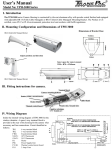
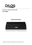
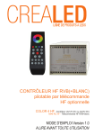
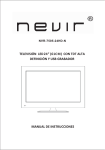
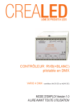
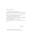
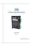
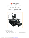
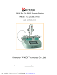
User’s Manual
Model No: TPH-5500 Series
I. Introduction
The TPH-5500 series Camera Housing is constructed from die-cast aluminum alloy with powder coated finish and is
equipped with an adjustable Fully-Cable-Managed Mounting Bracket. The product is CE certified and has environmental
protection level IP 68 or IP 44 with blower, Reach and RoHS compliance.
II. Mounting Configuration and Dimensions of TPH 5500
Adjust position and direction
BR-13 Fully-Cable Managed Bracket
Dimensions of Bracket Base
Inner space for camera mount
W60 x H80 x L260mm
III. Fitting instructions for camera.
Ground wire
Cable conducts
Terminal block assembly
Camera mounting platform
Heater shield
Blower
Heater
Power supply unit (option)
Thermal control board
IV. Wiring Diagram
Inside the internal wiring diagram of TPH 5500 for the
window demister. A spare 6 way terminal block is
provided at the rear of the housing for the camera when
necessary and lens connections. Circuit identified as
follows:
TB.1
TB.2
FTB.1
STAT.1
STAT.2
H.1
PSU
P.C.B.1
FS.1
6 way terminal block
3 way terminal block
Fused terminal block
18℃ Thermostat
35℃ Thermostat
Heater
Power Supply Unit
Thermal control circuit board
3 Amp. Fuse
Trans Pacific Industries Corp.
5F, No.79 Jen-Ai Road Section 4, Taipei 106, Taiwan
Tel: (+886 2) 2721-8956
Fax: (+886 2) 2731-4574
http://www.transpac-cctv.com
DC output of PSU connectors
AC power connection
1. Pin1,2 and pin 3,4 is DC 12V output for motor lens, IR illuminator,
siren or speaker use. If no use please remove cable from connector.
2. Pin 5,6 is for DC12V output for camera.
Shows how to connect the AC power cord to
the FTB. 1 connector.
V. INSTALLATION SUGGESTION:
If you plan to install this camera into a tropical, sear coastal, saltwater or corrosive industrial water/moist environment,
please seal each stainless steel screw and fittings with a silicon grease compounds. This will help prevent electrolysis
corrosive occurring and extend the lifespan of the camera and housing. The installation of a surge protection device is
strongly recommended in frequent thunder area.
!
IMPORTANT NOTE:
1. Disconnect Device: A disconnect device from main supply shall be incorporated in the building installation wiring.
2. Electrical Connections: Only a qualified electrician allow to make electrical connections.
Features Single heater
Double heaters*
Blower (IP44)
PSU (power supply unit)
1. Turn on at 18°C
1. Turn on at 18°C
1. Turn on at 35°C
1. 880 (80-260Vac input, 1x12Vdc output, 1A)
2. Turn off at 28°C
Turn off at 28°C
2. Turn off at 25°C
2. 080 (80-260Vac input, 4x12Vdc output, 3.5A)
2. Turn on at 0°C
3. 324 (24Vac input, 4x12Vdc output, 3.5A)
Turn off at 10°C
Model No.
4. 424 (24Vac input, 1x12Vdc output, 1.5A)
12Vdc / 24Vac 110 / 230Vac 12Vdc / 24Vac 110 / 230Vac
12Vdc
24Vac
880
080
324
424
5500
●
5500-12/24HS
●
●
5500-12/24HD
●
5500-012/F
5500-012/HF
●
●
●
5500-024/F
5500-024/HF
●
●
●
5500-110/230HS
●
5500-110/230HD
5500-080/HS
●
●
●
5500-080/HD
5500-080/F
5500-080/HF
●
5500-080/HC**
●
●
5500-324/HC**
●
5500-880/HF
●
5500-880/HC**
●
5500-424/HF
●
5500-424/HC**
●
●
●
●
●
●
●
5500-880/F
5500-424/F
●
●
●
5500-324/F
5500-324/HF
●
●
●
●
●
●
●
●
●
●
●
●
*First heater prevents moisture on the window glass till weather temperature -25°, second heater is heating in enclosure for camera operation properly till
weather temperature -40°
** With 12Vdc camera jet