1
REMOTE CONTROL AND TELEMETRY SYSTEMS
PUMP BOSS
RADIO CONTROL SYSTEMS
P/N: 142122-c
3/20/03
Rev. C
Radio Remote Control System
User's Manual
IMPORTANT
Read safety Rules & Instructions before using.
REMTRON, INC.
1916 W. Mission Rd., Escondido, CA 92029-1114
PHONE 760-737-7800
FAX 760-737-7810
REMTRON, INC.
1916 W. Mission Rd., Escondido, CA 92029-1114
PHONE 760-737-7800
FAX 760-737-7810
REMTRON, INC.
PUMP BOSS® RECEIVERS
The PUMP BOSS® Series receivers have been tested and found to
comply with the limits for a Class B digital device, pursuant to Part 15
of the FCC Rules. These limits are designed to provide reasonable
protection against harmful interference in a residential installation. This
equipment generates, uses, and can radiate radio frequency energy
and, if not installed and used in accordance with the instruction manual,
may cause harmful interference to radio communications. However,
there is no guarantee that harmful interference will not occur in a particular installation. If this equipment does cause harmful interference
to radio or television reception, which can be determined by turning
this equipment on and off, the user is encouraged to try and correct
the interference by one or more of the following measures:
•
•
•
Reorient or relocate the receiving antenna connected to the
device that is receiving the interference.
Increase the separation between our equipment and the
equipment that is receiving the interference.
Consult our factory or one of our Service Representatives
for additional help.
Responsible Party:
Remtron, Inc.
1916 W. Mission Rd.
Escondido, CA 92029
Ph:
800 328-5570
760 737-7800
ANTENNA MOUNTING TEMPLATE
How to Get Service
Products returned for repair (warranty or non-warranty) must be assigned
an RMA (Return Material Authorization number by a Remtron Technical Support
Representative. To allow us to more effectively address the repair issues, the
customer is to provide a detailed description of the specific problem. Call 800328-5570 for service or RMA assignment. To receive warranty service deliver or
send the product(s) along with the assigned RMA number to our factory.
All repairs are performed at the Remtron factory in Escondido, California.
This ensures that all parts of the remote system are maintained to factory
standards. Repairs are billed at a flat rate irrespective of time, however, external
damage caused by misuse, accident, neglect or damage to the case or other
assembly components could incur additional costs.
Please include your name, address and a telephone number in case our repair
technicians need more information. Enclosing a detailed description of the problem
will allow us to give you better service.
REMOTE CONTROL AND TELEMETRY SYSTEMS
PUMP BOSS
RADIO CONTROL SYSTEMS
Radio Remote Control System
User's Manual
P/N: 142122-c Rev. C dated 3/20/03
IMPORTANT
Read safety Rules & Instructions before using.
REMTRON, INC.
1916 W. MISSION RD.
ESCONDIDO, CA 92029-1114
(760) 737-7800 FAX (760) 737-7810
20
REMTRON, INC.
1916 W. Mission Rd., Escondido, CA 92029-1114
PHONE 760-737-7800
FAX 760-737-7810
Warranty Statement
for
Pump Boss
®
Concrete Pumping Products
Period of Warranty: Remtron warrants the Pump Boss against malfunction or breakage for a period of
one year from the date of purchase or one year from the date of the original invoice if the warranty
registration card is not received.
Warranty Coverage: Pump Boss transmitters, receivers and accessories, in normal and customary use,
are conditionally warranted against malfunction or breakage. The warranty does not cover: (a) defects
or damage resulting from use of the product in other than its normal and customary manner; (b) defects
or damage from misuse, accident or neglect; (c) defects from improper testing, operation, maintenance,
installation, alteration, modification or adjustment; (d) damage from unauthorized repair or alterations;
and (f) damage from water or corrosive materials beyond the specification of the case or enclosure
Warranty Service: Products returned for repair (warranty or non-warranty), must be assigned an RMA
(Return Material Authorization) number by a Remtron Customer Service representative. To allow us to
more effectively address the repair issues, please provide a detailed description of the specific problem.
Call 800-328-5570 for service or RMA assignment. To receive service, deliver or send the product(s)
along with the assigned RMA number to our factory at 1916 W. Mission Rd., Escondido, CA 92029.
General Terms of Warranty: Remtron will repair or replace the defective unit, solely at our option in the
event of defect or failure to perform as specified, provided the product is returned in accordance with the
terms of this warranty. Replacement parts are covered for the balance of the original warranty.
All costs of shipping to Remtron shall be borne by the purchaser. The warranty covers the cost of return
one-way shipping and handling of the product. The return shipment will be via the same method as the
product was shipped.
This warranty does not cover the costs of outside repair service except as authorized by Remtron. If it is
determined that a third party is necessary for the service or repair of the Remtron product, prior approval
by Remtron is required.
This warranty sets forth the full extent of Remtron’s responsibility regarding the product(s). Repair,
replacement or refund of the purchase price, at Remtron’s option are the exclusive remedies. This
warranty is given in lieu of all other express warranties. All other warranties, expressed or implied,
including without limitation implied warranties of merchantability or fitness for a particular purpose ,
are specifically excluded. In no event shall Remtron be liable for damages in excess of the purchase price
of the product(s), for any loss of use, loss of time, inconvenience, commercial loss, lost profits or savings
or other incidental, special or consequential damages arising out of the installation, use or inability to
use the product(s), to the full extent that such may be disclaimed by law.
19
8. Reassemble the transmitter in reverse order. Make sure the battery wires
do not get pinched between the case halves.
Replacement Parts
TABLE OF CONTENTS
WARNING INSTRUCTIONS ........................................................................ ii
Replacement parts are available from the distributor where you purchased
the system or directly from the Remtron factory. When ordering a spare or
replacement transmitter, provide the Serial Number of the receiver or the Model
and ID Code of the receiver or transmitter. The Serial Number has the form:
S/N 9923-3. The ID Code has the form: ID Code: 230C8D.
DESCRIPTION ................................................................................................... 1
Transmitters .......................................................................................................... 2
Receivers ................................................................................................................ 2
Receiver/Decoder ................................................................................................ 3
USING YOUR SYSTEM ................................................................................... 4
Pump Boss ® Spare Parts List
Description
Part No.
Leather holster
620006-03
Shoulder strap for transmitter
600008-02
Weather resistant, clear plastic carry bag for transmitter
(shoulder strap not included)
620011
900 MHz 12” coil whip antenna (no coax, no mount)
485022
900 MHz antenna mount with 3’ coax (no antenna)
920053
900 MHz long range antenna
RCA7
Replacement Rubber Keypad
920030-03
Portable Programmer
RAC16
INSTALLATION ................................................................................................ 6
Antenna Installation ........................................................................................... 7
Locating the Antenna ......................................................................................... 7
Standard Antenna Mount .................................................................................. 7
RCA7 Extended Range Antenna ...................................................................... 9
Wiring Instructions .............................................................................................. 10
Pump Boss ® Electrical Connections (pictorial) ............................................. 12
HELPFUL HINTS ............................................................................................... 13
TROUBLESHOOTING .................................................................................... 14
System Does Not Operate .................................................................................. 14
Insufficient Range ................................................................................................ 14
Transmitter Troubleshooting ............................................................................. 15
TRANSMITTER REPAIRS .............................................................................. 16
Battery Replacement ........................................................................................... 16
ID Code .................................................................................................................. 16
Changing the Transmitter Keypad ................................................................... 17
Replacement Parts ............................................................................................... 18
WARRANTY STATEMENT ............................................................................ 21
How to get service ................................................................................................ 22
18
i
WARNING !
READ ALL INSTRUCTIONS
Failure to follow the SAFETY RULES
may result in serious personal injury.
INSTALLATION
* PROVIDE A SAFETY CUTOFF SWITCH. If maintenance is required,
the radio must be disconnected from power to prevent accidental pump
activation.
*
USE PROPER WIRING. Loose or frayed wires can cause accidental
pump activation.
* DO NOT INSTALL IN HOT AREAS. This apparatus can be damaged
by heat in excess of 160 F.
* DO NOT INSTALL IN HIGH VIBRATION AREAS. The life of this
apparatus may be shortened through long exposure to intense shaking
or vibration.
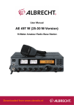
Changing the Transmitter Keypad
1. Remove the screws in the back of
the transmitter and remove the
back of the case. Remove the
batteries from the holder.
3. Remove the nuts from the studs
holding the support plate to the
case front.
4. Remove the backing plate and
rubber keypad from the case front.
(Remove These
Screws to Replace
Keypad)
5. Install the new rubber keypad onto
the backing plate, making sure the
tabs are pulled through each slot.
6. Install the keypad and backing
plate into the case front.
7. Apply a small amount of Torque
Seal® to the threads on the studs
and install the nuts on the studs
finger tight plus 180 degree turn.
DO NOT use Loctite ® as most
formulations will cause the plastic
to become brittle.
Programming
Plug
123456789012345678901234567890121234567890
123456789012345678901234567890121234567890
123456789012345678901234567890121234567890
123456789012345678901234567890121234567890
123456789012345678901234567890121234567890
123456789012345678901234567890121234567890
123456789012345678901234567890121234567890
123456789012345678901234567890121234567890
123456789012345678901234567890121234567890
123456789012345678901234567890121234567890
123456789012345678901234567890121234567890
123456789012345678901234567890121234567890
123456789012345678901234567890121234567890
123456789012345678901234567890121234567890
123456789012345678901234567890121234567890
123456789012345678901234567890121234567890
123456789012345678901234567890121234567890
123456789012345678901234567890121234567890
123456789012345678901234567890121234567890
123456789012345678901234567890121234567890
123456789012345678901234567890121234567890
123456789012345678901234567890121234567890
123456789012345678901234567890121234567890
123456789012345678901234567890121234567890
123456789012345678901234567890121234567890
123456789012345678901234567890121234567890
+
+
MAKE SURE MACHINERY IS CLEAR BEFORE OPERATING. Do
not activate the Remote system unless it is safe to do so.
* TURN OFF THE RECEIVER POWER BEFORE WORKING ON
MACHINERY. Always disconnect the remote system before doing
any maintenance to prevent accidental operation of the machine.
i
Printed
Circuit Board
Assembly
2. Remove the screws holding the
printed circuit board assembly and
remove the board from the case.
PERSONAL SAFETY
*
ID# 28008C
Transmitter
with Back Removed
17
TRANSMITTER REPAIRS
Battery Replacement
Note that when the battery is getting very low, the transmitter LED will
change from quick flashes to a deliberate on/off cycling. When this occurs, or at
least every year, replace the transmitter battery. Alkaline AA batteries should be
used for long battery life.
CAUTION!
The transmitter electronic components are exposed when the back
of the case is removed. Take caution to prevent dirt or other
contaminants from entering the case. Do not allow the circuit
to be scraped or damaged in any way.
Refer to the figure of the transmitter with back removed.
Remove the four screws on the bottom of the transmitter case and separate
the case halves. Be careful not to damage the circuitry or get dirt inside the case.
Be sure to observe the correct polarity when installing the new batteries.
Reassemble the case and screws.
Alkaline AA batteries should be used for long battery life. Rechargeable
batteries are not recommended.
ID Code
Both the transmitter and receiver have a 6 digit identification code (ID Code)
contained in memory. This ID Code must be the same for both the transmitter
and receiver for the system to operate. The codes are set at the Remtron factory
such that no two systems are alike.
DESCRIPTION
The Pump Boss ® systems are essentially remote controlled switches consisting
of a hand held transmitter and a pump mounted receiver. These systems provide
a fail safe emergency stop feature which insures that the radio control system is
working properly and is in “radio range” at all times the unit is operating.
When the operator presses a switch on the transmitter, a digital message is
sent via radio waves to the receiver. The digital message contains one of millions
of possible ID Codes. This unique code makes it possible for the receiver to respond
only to the proper transmitter. Additional codes are also sent that make false
commands, for any reason, impossible.
Self healing fuses rated at approximately 4 amps protect the output relays of
the receiver. If too much current is drawn through the relay, the fuse will open
and remain open as long as electricity is applied through the relay. Once electricity
is removed, the fuse will heal itself and be ready to operate in about 1 minute.
Each receiver is provided with a permanently mounted antenna.
NOTE
Radio waves are however effected by any metallic objects and
difficulty operating in certain locations may be encountered. Read
the section on using your system on getting the best performance
from your system.
These systems comply with the requirements for operation under Part 15 of
the FCC rules and regulations. This means that neither the operator nor the
company need apply or register for a license to operate this equipment.
The RAC16 portable programmer may be used to read and to change the ID
Code. The RAC16 may be ordered from your dealer. If you do not have access to
a RAC16, bring the unit(s) to your dealer or send them directly to the Remtron
factory for programming.
16
1
DESCRIPTION (continued)
Transmitter Troubleshooting
Transmitters
The transmitters that are used with the Pump Boss ® systems are housed in
rugged cases molded from a modified polymer plastic that stands up to extremely
rugged use. A key feature is Remtron’s patented switch assembly for control
inputs. This long-life elastomeric keypad is ergonomically designed to provide
easy operation over long periods of time with exceptional reliability. A leather
holster provides added protection and convenience. An optional water tight pouch
is available from your dealer.
The transmitters are designed to be very efficient, operating from two AA
batteries. To ensure long battery life, the transmitters will shut themselves off
after one hour of inactivity. The antenna is internal to the transmitter case,
protecting it from damage. A self-test LED indicator provides a quick visual
check of transmitter and battery status.
Receivers
The receivers are housed in rugged aluminum cases with end caps molded
from a modified polymer plastic that stands up to extremely rugged use.
Connection to the receiver are made through a multi-conductor cable.
Pump Boss
PBT1ES
®
TRANSMITTERS
PBT2ES
PBT3ES
2
The transmitters have an LED status indicator to aid in troubleshooting.
Due to the rough treatment it may be subjected to, most problems are likely to
occur in the transmitter. The transmitter should be thoroughly diagnosed before
proceeding to the receiver.
WARNING!
When testing the transmitter, the receiver may become active
resulting in system operation. Always assume the system is
working and will respond when testing a transmitter.
Troubleshooting Chart:
LED Indication
Possible Cause
LED is off.
Transmitter is off.
LED flashes at low rate.
Transmitter is operating in a normal mode.
LED flashes at high rate.
Command Switch is pressed.
LED flashes on-off.
(½ second on and ½ second
off while the transmitter is on).
Batteries getting low. Batteries should be
changed at the next convenient opportunity.
LED on continuous.
Either a switch was activated at the time the
transmitter was turned on or a general failure
occurred that requires factory service. Ensure
no command switches are pressed while
attempting to turn the transmitter on.
LED will not light.
Replace batteries. If this does not correct the
problem, the transmitter must be repaired.
PBT4ES
15
TROUBLESHOOTING
System Does Not Operate
a) Check that the transmitter (see transmitter troubleshooting on the next
page).
b) Make sure the receiver POWER LED is lit. If not, determine if +12 VDC is
present between the red and black wires of the receiver.
c) Check that the receiver ACTIVE LED lights when the transmitter is turned
on. If not, check that the transmitter and receiver ID Codes are the same.
d) Examine the receiver “Function” LEDs. If they indicate the proper function
is operating, the problem is usually external to the receiver.
e) If the system shuts off after a few minutes of operation, even when the
transmitter is well within operating range, the receiver’s self healing fuse
may be activating. This may be caused by the receiver getting too hot or
from a solenoid that is drawing too much current. Move the receiver to a
cooler location or replace the solenoid on your pump.
Insufficient Range
Check that the receiver antenna is installed properly and is not touching
metal.
If using the standard antenna mount, make sure the bottom of the antenna
mount is making contact with metal. Note that the antenna works best when
mounted on a metallic surface. If mounted on fiberglass or other nonmetallic
surfaces glue aluminum foil or place an aluminum plate on the bottom of the
mounting surface covering at least 10 inches in diameter around the antenna
mount. Make sure the metal is connected to the bottom of the antenna mount
and is not touching the center terminal of the mount.
DESCRIPTION (continued)
The safety relay is controlled by the microprocessor and by a hardware circuit
to ensure operation even in the event of circuit failure. During normal operations,
this relay is closed (activated). If for any reason valid data is not being received,
this relay will open. It is also opened any time an operator sends an E-Stop
command.
The use of surface mount parts and and special floating circuit board mount
inside a waterproof case make the Pump Boss ® receivers mechanically strong.
15 Amp relays, self healing fuses and advanced programming make them
electrically able to stand up to the expectations of your pumping environment.
The use of a maintained radio link plus three levels of safety insure the control is
there when you need it.
Receiver/Decoder
The Receivers use an advanced synthesized FM Receiver designed to work
in the presence of potential interfering signals such
as might be encountered from pagers, cell phones,
two way radios, etc. The microprocessor- based
decoder insures a great deal of safety as well as
versatility. Commands are received on one of 81
possible frequencies and are checked against a
16-bit address code for proper identity and further
tested against a 16-bit CRC check code. This
insures only valid information meant only for the
particular unit is decoded.
The receiver assembly monitors and indicates
its status on a continuous basis. The diagnostics
are presented in a simple, easy to understand
format.
Pump Boss ®
RECEIVER
14
The POWER LED lights when power is applied
to the receiver. The ACTIVE LED lights when a
valid signal is being received from the transmitter.
Other LEDs light to indicate that a command
function is activated.
3
USING YOUR SYSTEM
HELPFUL HINTS
WARNING !
If the Pump Boss does not operate properly, check the wiring. Always make
sure the electrical connections are clean and tight. Pumps vibrate and loose wires
can easily become disconnected. It is also a good idea to tie the wires from the
receiver to solid points to keep them from swaying.
Before operating the remote control system, make sure it is
safe to do so. Make sure the same safety precautions
normally required for safe pump operation are adhered to.
DO NOT leave the transmitter unattended
while the pump engine is operating.
WARNING!
The Pump Boss uses a self healing fuse device in line with each relay. If the
receiver is overloaded, the fuse device will open to protect the unit. When it cools
down, the device will close restoring normal operation to the output.
When using inductive loads such as solenoids or motors, connect the wires
according to the instructions. Internal circuits in the receiver will then protect the
relay from high energy voltage spikes that may be produced by the load, thereby
ensuring long reliable life of the relay.
Do not operate the system until you are familiar with the
operation and safety procedures for the pump.
IMPORTANT
IMPORTANT
The Emergency Stop button for the system is the OFF/ESTOP
button. Press and hold this button to stop all functions.
Place the ignition switch ON to power up the receiver. Verify the receiver
POWER LED is lit. If not, check the power connections to the receiver.
Press the transmitter ON switch. The transmitter LED should slowly flash
and the receiver ACTIVE LED should light.
Note that the antenna for the transmitter is located inside the top of the
transmitter case. Normal range should be achieved with the transmitter worn on
your body. Extended range and operation in difficult areas can be achieved by
moving the transmitter away from your body or holding it in the air. Pointing the
transmitter towards the receiver will provide the greatest signal.
4
Water may enter the receiver through the jacket of the
electrical cable if the outer jacket is cut close to the receiver
case. To minimize the chance of this happening, leave a
minimum of 6 inches of outer jacket on the electrical cable
and position the open end of the jacket so that it faces
downward.
IMPORTANT
This system operates in a fail safe mode. If the receiver does
not receive a signal for about 10 seconds, it will open the
safety relay and turn off all output relays. To restart the
operation, move the transmitter within signal range of the
receiver and again command the Pump, Reverse and Throttle
commands as necessary.
13
Pump Boss
®
Electrical Connections
Pump Start/Stop (All Models)
Fuse
Receiver
Power
{
Red
!
Black
Blue
Orange
Brown
White
Green
Purple
Grey
Yellow
Tan
Pink
}
Ignition
Switch
Safety Switch
Wires
-
(Alternate Relay Input)
12 V
Battery
+
To start the pump, momentarily press the transmitter switch to PUMP. This
will close the pump relay in the receiver and allow the pump to operate. The
receiver PUMP LED should light. To stop the pump, momentarily press the
transmitter switch to STOP. The receiver PUMP LED should go out.
To turn the transmitter off, press the OFF/ESTOP button. (Note that the
transmitter will turn itself off if no commands are sent for 1 hour.) This will
release the safety relay in the receiver and stop all functions. When released, the
transmitter will be turned off.
Pump Reverse (PBS2ES, PBS3ES and PBS4ES)
Output To Pump Solenoid
To reverse the pump, momentarily press the transmitter switch to REV. This
will close the Reverse relay in the receiver and reverse the pump. The receiver
REVERSE LED should light. To change to forward, momentarily press the
transmitter switch to FWD. The receiver REVERSE LED should go out.
12 VDC Relay Input
Not Normally Used
Direction Output
12 VDC Relay Input
High Throttle Output
12 VDC Relay Input
}
Direction
Switch
Wires
}
Throttle
Switch
PBR3ES ONLY
12 VDC
Tan
}
(Increase)
Pink
(Decrease)
Throttle Wires
(Connect to Servo Motor)
PBR4ES ONLY
Throttle High/Low (PBS3ES)
To increase the throttle, momentarily press the transmitter THROTTLE
switch to INCREASE. This closes the throttle relay in the receiver and increases
the throttle. The receiver THROTTLE LED should light. Pressing the transmitter
THROTTLE switch to DECREASE opens the throttle relay, extinguishing the
receiver THROTTLE LED and reduces the engine speed.
Variable Throttle (PBS4ES)
To increase the throttle, press the THROTTLE switch to INCREASE. This
closes the increase throttle relay in the receiver and increases the throttle as long
as the switch is depressed or until maximum throttle is reached. The receiver
THROTTLE LED should light while the switch is depressed.
To decrease the throttle, press the THROTTLE switch to DECREASE. This
closes the decrease throttle relay in the receiver and decreases the throttle as long
as the switch is depressed or until minimum throttle is reached. The receiver
THROTTLE LED should light while the switch is depressed.
RECEIVER BOX
12
5
INSTALLATION
NOTE: Since pump machines will vary between different manufacturers, some
connections may be different than are listed in this manual. If you have questions
on your installation call Remtron Customer Service for assistance.
CAUTION !
DO NOT INSTALL THE RECEIVER NEAR
EXHAUST PIPES OR IN OTHER HOT AREAS
This Pump Boss
®
system consists of:
INSTALLATION (Continued)
Wiring Instructions (continued)
WIRE
COLOR
WIRE
FUNCTION
CONNECTION
Reverse Switch
Purple
Not Normally Used
Grey
Relay Input
Connect to +12 VDC power source
Yellow
Reverse Relay Output Connect to the “REVERSE” side of the pump
Fwd/Rev switch.
Hand Held Transmitter
Throttle Control (PBR3ES ONLY)
Receiver with attached multiwire cable
Tan
High Throttle Output Connect to Throttle Increase
Antenna and antenna mount with coaxial cable
Pink
Relay Input
Connect to +12 VDC power source.
Throttle Control (PBR4ES ONLY)
Mechanical
Tan
Servo Increase
Connect to Servo Motor +.
In selecting a place to mount the receiver consider the following points:
Pink
Servo Decrease
Connect to Servo Motor -.
Access to the wiring for the control box on your machine.
Notes
Protection from mechanical damage during towing or during use.
Pump Relay Power Input
The GREEN wire is normallly used for the pump switch Input. On pumps
with reversed logic, i.e.; voltage is applied to stop pumping and removed to start
pumping, the BROWN wire must be used for the Input.
Select a location with a flat mounting surface.
If possible, protect the receiver from direct exposure to sun and rain. Even
though the receiver is weather resistant, it’s still a good practice to protect
it from the elements.
Securely mount the receiver box to the pump. Secure the box to the surface using
#10 hardware.
6
Safety Switch
The receiver contains a safety switch that is activated when the hand held
transmitter is ON and within operating range of the receiver. If the pump is
equipped for use of an emergency stop switch, connect these wires to this circuit.
If your pump is not equipped with an emergency stop circuit, connect the
ORANGE wire to the GREEN wire using a wire nut. Use the BLUE wire in place
of the GREEN wire for the Pump Switch Input connection.
11
INSTALLATION (Continued)
INSTALLATION (Continued)
Antenna Installation
Wiring Instructions
NOTE
All connections are made to the pump with a cable that is supplied with the
Pump Boss ® system. Refer to the wiring diagram and application notes for
reference. Improper Installation could cause damage to the pump and/or the
Remtron control. Qualified personnel should make all electrical installations.
Proper antenna installation is essential for peak performance
of the Pump Boss. Take care to install the antenna properly.
The relays in the Pump Boss ® receiver are rated to provide long trouble free
service. This long life can be ensured by using the connections as listed in the
table below.
Two different styles of antenna are available for the Pump Boss ® systems.
Both must be permanently attached to the pump for proper performance.
For safety, disconnect the battery prior to installing the Pump Boss
control system.
WIRE
COLOR
WIRE
FUNCTION
®
radio
CONNECTION
Basic Power
Red
Power
Connect to fused 12VDC. Recommend
connection be made to a point that can be
switched on by ignition (possibly ignition
switch itself).
Black
Ground
Connect to negative battery supply (usually
bare metal on pump chassis).
Locating the Antenna
For best reception, the antenna must be mounted to a horizontal surface
with the top of the antenna at least 8 inches away from all major metal structures
(vents, spash panel, exhaust, etc). There should be a clear line-of-sight between
the antenna and the transmitter when pumping. The top of the pump hood is an
excellent mounting location.
To ensure trouble-free performance, the cable should be routed away from
sources of heat such as the engine block, exhaust manifold and exhaust pipe. The
cable is rated for a maximum of 185O F. The cable must be secured in an out-ofthe-way location where it will not be crushed or snagged. Before mounting the
antenna, make sure the cable will reach the receiver box.
Standard Antenna Mount
Safety Switch
Orange
Safety Switch
See Notes
Blue
Safety Switch
See Notes
Tools Needed:
Drill or punch for 3/4 inch dia. hole.
Pump On/Off Control
Brown
Alt Pump Relay In
See Notes
Green
Pump Switch Input
Connect to 12 VDC power source.
White
Pump Switch Output Connect to the “ON” side of the pump on/
off switch
10
The standard antenna mount accepts the whip type of antenna.
7
INSTALLATION (Continued)
INSTALLATION (Continued)
Drill or punch a clean 3/4 inch hole in the panel where the antenna will be
mounted. Take care to make a smooth hole for the mounting surface. Hole
saws are available from most hardware and home maintenance stores. Remove
paint in a narrow ring around the underside of the hole. Note that metal-tometal contact between the vehicle and the antenna mount will provide the best
performance.
If installation is on a fiberglass or other non-metallic surface, a minimum 10”
diameter (or square) metal plate or foil must be placed under the mount to achieve
proper performance from the antenna.
Unscrew the black insulator nut from the antenna mount. Place the mount
on the bottom center of the hole and screw the insulator nut onto the stud. Make
sure the mount is centered on the hole. Be sure the antenna mount center stud
does not contact any metal. Tighten the insulator nut using the small allen wrench
supplied with the mount. Do Not overtighten.
Route the cable to the receiver and secure with cable ties.
RCA 7 Extended Range Antenna
Tools Needed:
Drill or punch for 3/16 and 5/8 inch dia. holes.
#1 Phillips screwdriver
Center punch
Adhesive tape (such as masking tape)
The RCA7 extended range antenna provides greater operating range than
the standard antennas. It is mounted directly to the pump. An antenna mounting
template is located on the back cover of this manual.
Installation Prodedure:
1. Tape the mounting hole template to the mounting surface. Locate the
four hole centers on the mounting surface by punching through the paper
template with the center punch.
2. Remove the template and drill the four holes as indicated on the template.
Insulator
Nut
O-Ring
3. Feed the antenna cable through the center (5/8” Dia.) hole. Insert the
rubber grommet in the hole to protect the cable from chafing. Note that
two grommets are supplied on each cable to accommodate either a 5/8”
Dia. or a 3/4” Dia. hole. Cut off the unused grommet.
4. Secure the antenna using the #6 hardware supplied. Insert the screws
through the antenna and secure with the lockwashers and nuts.
5. Route the cable to the receiver and secure with cable ties.
Standard Antenna Mount Installation
8
9