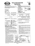
1
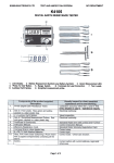
GSM Motion Detector
insert a SIM card
release the battery pins
www.alpha-safe.com
~
EXPRESS
~
EXPRESS
Dear Customer'!
GSM MOTION DETECTOR
EXPRESSE3
Thank you for choosing our state of the art high tech security product. In order for this
product to se.-ve you for a longtime, please familiarize yourself with this operating manual. In the event
that you would like to make any suggestions or comments, please do not hesitate to contact us by
using the information located at the back of this manual. Your opinion is important to us.
OPERATING MANUAL
This Operating Manual was specifically written in order to cover all aspects of EXPRESS E3
installation and operation.
CONTENTS
1
DESCRIPTION AND FUNCTION
1.1
Purpose
5
5
5
1.2
Technical specifications
1.3
Motion Detector package contents
1.4
Motion Detector structural design
6
6
1.5
Keychain Remote Controller structural design
7
1.6
Device set-up and operation
7
2
SET-UP PROCEDURE
2.1
Preparing the device for operation
2.2
Setting up 1he Motion Detector
2.3
Entering the programming mode
9
9
10
12
13
13
14
15
16
16
16
17
19
20
20
2.4
Erasing the phonebook and SMS messages
2.5
Initial programming (set-up)
2.6
Adjusting the settings
2.7
Adding a telephone number for notification messages
2.8
Erasing notification message telephone numbers
2.9
Erasing a Keychain Remote Controller
2.1 D
Installing the Motion Detector
2.11
Arming and disarming the Motion Detector device
3
Troubleshooting
4
Contact Information
5
Warranty Coverage
3
4
~
EXPRESS
DESCRIPTION AND FUNCTION
1.3
1.1
Purpose
This EXPRESS E3 GSM Motion Detector (further referred to as Motion Detector) was
specifically designed to detect penetration of a protected zone and to transmit notification via a call and
SMS text message to a GSM standard telephone; also to photograph the penetrated protected zone
and transmit an E-mail via GPRS.
EXPRESS E3 Motion Detector features:
- Installs in any location that has GSM mobile service;
- Arms and disarms the alarm via a three button Keychain Remote Control BN-3S (further
referred to as RC);
- Configures by mobile telephone, an online service or an iOS/Android app- "Express-GSM
Configurator'';
- Operates on two AA batteries for up to six months;
- Power saving economy mode available;
-Automatically detects remaining balance and GPRS settings (four major service providers);
- Request remaining balance using the RC;
- Controlled via a mobile telephone;
The Motion Detector performs the following functions:
- Determines human movement in a protected zone;
- Places an alarm call and transmits an SMS text alarm;
- E-mails a photograph via GPRS;
- Sends a SMS text message confirming armed/ disarmed alarm mode;
- Sends a remaining balance status SMS;
1.2
~
EXPRESS
Motion Detector package contents
Motion Detector package contents in accordance with chart 2.
Chart 2 - Motion Detector contents
Description
Quantity
GSM Motion Detector EXPRESS E3
1
AA Batteries LRS 1.5v
2
User manual
1
Keychain (RC) Remote Control BN-3S
1
1.4
Motion Detector design structure
Structurally the Motion Detector consists of a main body base, a front cover, a rear lid
(removable), detector circuit board and GSM module circuit board (refer to fig. 1, 2). The detector and
GSM module circuit boards attach to the main body base with stand off tabs.
A SIM card holder is installed on the GSM module circuit board; and a battery holder, GSM
light diode signal indicator, a built-in announcer and button (refer to fig. 2) are installed on the detector
circuit board.
Batteries are installed in the device and are insulated from the contacts by means of a
plastic protective insulating Insert (refer to fig. 2).
The Motion Detector is designed for use on a wall and can be mounted using a screw that
utilizes a special cutout found on the back of the Motion Detector main body base (refer to fig. 2).
Technical specifications
Basic technical specifications are shown in chart 1.
Chart 1 - Basic Technical Specifications
main body base
Parameter Description
Value
Maximum distance at which human presence is determined
10m
Maximum RC operatina ranae
15m
Maximum distance reauired to photoaraph with no liahtina
2m
1sec
Trigger time required to activate camera after penetration
Quantitv of ohotoaraohs at oenetration
1or2
GSM module operating standards
GSM 900/1800/1900
Maximum number of telephone numbers to be notified
6
Maximum number of RC units for arming/ disarming
6
Elapsed time for notification
20-40 Sec
Battery tvoe
2 xAN LR61 .5v
Un-interrupted operatina duration usina one set of batteries
up to 6 months
Quantity of dispatched photographs via e-mail during un-interrupted
up to 60
operation
-10c-+50c
Operatina temperature ranae*
Relative humidity at a temperature of +35c without moisture
93%
condensation not to exceed
up to 6 months
Operating duration at a temperature of +25c
Overall dimensions
110 x 66 x 57.5 mm
*- The Motion Detector can operate under temperatures as low as -25c with a reduction in the uninterrupted operating span resulting in fewer SMS messages and photographs being sent.
5
~
camera lens
front cover
rear lid
Fig. 1 Overview of the Motion Detector structural design.
6
~
EXPRESS
-requests remaining Motion Detector SIM card balance and transmits an SMS to the
handheld mobile device;
-auto reset to armed mode;
-auto detection of telephone number for remaining Motion Detector SIM card balance and of
GPRS* settings;
-disarm alarm mode via a telephone call after triggered alarm.
*Footnote- for mobile providers T-Mobile, AT&T, Orange & Vodafone.
I
special cutout
for mounting screw
GSM light diode
signal indicator
~
SIM card holder
_.---1'
~ GSMmodulecircuitboard
~
protective
insulating insert
~
EXPRESS
dete~tor
~
+
power source
batteries
battery holder
Basic Keychain Remote Control functions
The Keychain Remote Control executes the following functions:
-arms the Motion Detector using button "A";
-disarms the Motion Detector using button "B";
-requests remaining Motion Detector SIM card balance using button "F";
-quick exit out of programming mode using button "F" (see 2.3)
Keychain Remote Control and Motion Detector indicators
The Motion detector was designed with light and sound indicators. The GSM light diode on the
detector circuit board indicates the state of the GSM network. The light diode on the Keychain Remote
Control indicates armed/ disarmed mode, communication with the Motion Detector and balance
inquiry. Indicator descriptions are detailed in Chart 3.
Fig. 2 Motion Detector structural design with rear lid removed.
Chart 3 - Motion Detector and Keychain Remote Control Indicators:
1.5
Keychain remote control structural design
The keychain Remote Control structural design consists of a base, a cover, button unit (3
button) and a light diode (refer to fig. 3).
Inside the keychain Remote Control is a CR2032 Lithium 3v battery. In order to replace the
power source, it is necessary to remove the screw, lift the cover, remove the depleted battery and
then, observing polarity, install a new battery. Replace the cover and tighten it using the screw.
lighldioda
main body base
button body:
buttons A,B & F
~
~
screw
Fig. 3 Overview of the keychain Remote Control structural design.
1.6
Device set-up and operation
Basic Motion Detector functions
The Motion Detector executes the following functions:
- detects movement within a 10m protected zone;
- places calls and transmits triggered SMS alarm messages to the telephone numbers
registered on the Motion Detector SIM card;
-photographs the protected zone when triggered by penetration;
-transmits a photograph via GPRS to the e-mail address registered on the Motion Detector
SIM card;
-transmits an SMS message confirming armed/ disarmed modes;
7
Event
RC Indicator
MD Sound Indicator
"GSM" light diode
Indicator
Power on
----
1 audio beep
----
GSM network search
- ---
--- -- ---
Successful GSM
network
reaistration
Erasing Phone book
memorv
MD Receive/
send SMS
RC successfully
oroarammed
RC
previously
proarammed
Waiting for MD
to confirm armed/
disarmed mode
Enter armed mode
----
3 beeps
Constant
flashing
20-40 sec.
1 time in 5 sec.
-------
multiple short beeps
---------
------
1 or multiple beeps
---------
alternate red/ green
flashes
alternate red/ green
flashes
briefly glows yellow
1 beep
---------
2 beeps
---------
1 beep
---------
briefly glows red
--------
---------
Enter disarmed
mode
Remaining
balance inquiry
via F button
briefly glows green
2 beeps
---------
flashes yellow
--------
---------
8
~
EXPRESS
Notifications
The Motion Detector transmits an armed/ disarmed status SMS message to "1SMS" (the 1st
notification telephone number, refer to chart 4) as recorded in the SIM card memory and a triggered
alarm SMS notification to the telephone numbers designated at "1SMS" - "6SMS" (figs. 4-6).
Additionally, the telephone number designated at "1SMS" receives status and setting messages.
Status messages are dispatched at the time intervals programmed. The time schedule
reference point is initiated and established upon receipt of the setting SMS.
The status message contains the remaining SIM card account balance.
When an alarm event is triggered, the Motion Detector transmits an SMS message and
places an outgoing call to the 1st (primary) telephone number and then subsequently calls the
additional telephone numbers.
The Motion Detector will terminate the outgoing call and proceed to call the next telephone in
the following case:
- When the subscriber is in network, but does not pick up after 30 seconds.
- When the subscriber is in network, but the line is busy after 5 seconds.
-When the subscriber is in out of network, after 10 seconds.
Dialing out will cease when one of the dialed subscribers responds to the call (by picking up
and/ or hanging up). Next, the Motion Detector will transmit an SMS "Alarm" text message to the
telephone numbers located at "2SMS" - "6SMS".
£
Alarm armed by Remote Control 1 (home)
J
£
2.2
Setting up the Motion Detector
At the initial power up using a new or an erased/ reformatted SIM card (see 2.4), the Motion
Detector will create an entry in accordance with chart 4. Motion Detector settings 1-26 are stored in the
SIM card memory and settings 27-31 are stored in the memory of the Motion Detector device.
Chart 4 - Motion Detector Settings
Cell#
position
J
Alarm disarmed by a call from +17180000000 (home)
J
000
2
3
4
2sms
3sms
4sms
5sms
6sms
BALANS
000
000
000
000
000
0
10
11
12
13
14
RC#1
RC#2
RC#3
RC#4
RC#5
RC#6
TEST
000000000
000000000 Unique individual Remote
000000000 Control
ID
number;
000000000 000000000 value defines
000000000 RC as not registered
000000000
7
Time interval for test/
status SMS notifications
16
ArmDisarm
2
17
AutoArm
60
18
AlarmNot
1
5
6
7
fig. 5 SMS "Disarmed•
.1.
ALARM (home)
Description
1sms
9
Alarm disarmed by Remote Control 1 (home)
Default
value
Cell label
1
8
fig. 4 SMS "Armed"
~L
~
EXPRESS
1st telephone number
(primary) for notification
Telephone
notification
numbers for
Remaining
inquiry USSD
balance
J
fig. 6 SMS "ALARM"
(home)- Motion Detector label name- (see 2.5)
Photographs
The protected zone is photographed not later than 1 second after penetration of the
protected zone is detected. After all the SMS messages are transmitted, the photograph is e-mailed via
GPRS. In the event the default settings are changed (see Chart 4, Cell#26 and Value#4); the protected
zone can be photographed 2 times after penetration. The second photograph is taken with a delay of 6
to 30 seconds after the initial photograph, depending on the selected value parameter setting.
2
SET-UP PROCEDURE
2.1
Preparing the device for operation
Unpack and visually inspect the Motion Detector to make sure nothing is damaged or missing.
Prior to proceeding with set-up, de-activate the PIN code feature on the Motion Detector SIM
card with the assistance of a GSM mobile telephone. (see user manual for the mobile telephone).
Confirm that the SIM card has a credit balance and connects to GPRSI Data.
In the event the SIM card was previously used, erase/ reformat the SIM card memory (see 2.4).
Sends SMS when armed/
disarmed mode activated
Reset time interval after a
triggered Alarm. After
Alarm
sending
an
notification, the Motion
Detector pauses for 30250 seconds prior to rearming. A notification that
the MD has re-armed is
not sent.
Type of Alarm notification
Enter number in the following
format+1 .."****"""
e.Q.:+17180000000
Enter number in the following
format+1 ..........
e.g.:+17180000000
Auto detection of balance
inquiry telephone number;
manual entry of tel.# is
oossible· e.a.: #225#Registers by pressing button
on RC while in programming
mode
Sets time interval for test/
status SMS notifications.
Interval sets in days, hrs &
min. (up to 30 days using two
digits). e.g.: 2 - every 2 days
12" - 12 o'clock
40#-40 min.
0- test/status notice not to be
sent.
0- do not send
2-send
Interval parameter must be
between 30-250 seconds.
e.g.: 0- one time Alarm
60-seconds
120- seconds
0- Only SMS to 1sms...6srns
1- Call + SMS (SMS sent to
1sms, then calls placed to all
tel. numbers, followed by
SMS
transmittal
to all
remaining tel. numbers @
2sms... 6sms.
Caution! While handling and working with the Motion Detector, take care not to touch the
camera lens with your fingers (fig.1). Touching the lens may result in poor picture quality.
9
Available values
10
~
EXPRESS
2- Only determines detection
zone & emits short audio
tone; SMS not sent & calls
not pieced.
3- Only calls placed to
1sms...6sms
19
AnnDelay
40
Arming delay in seconds
20
DisDelay
0
Notification delay, after
triggered alarm, in order
to facilitate disanning in
seconds
Battery economy mode
21
EcoBat
2
25
TriggerAlarm
1
26
Camera
2230
27
28
29
Settings
stored in
device
memorv
Settings
stored in
device
memorv
Settings
stored in
device
memory
--
Tums Motion Detector
during
sound
off/on
triooered alarm
Camera Adjustrnents(four
value digits)
Motion Detector
(signature
on
photograph)
name
the
should
Parameter
between 15-250 sec.
Parameter
should
between 0-250 sec.
30
Settings
stored In
device
memory
Settings
stored in
device
memorv
31
be
-
User name for the mobile
operator
Up to 30 characters d text
using the Latin alphabet
-
User password for mobile
operator
Up to 30 characters d text
using the Latin alphabet
be
0- Battery economy mode.
Disarms via Remote Control
only after triggered Alarm.
Efficient when the Motion
Detector is on guard for long
periods without the need for
disarming.
2- Normal mode. Disarming
via the Remote Control is
Dossible anvtime.
0-on
1- off
Value digit #1:
Image resolution:
1-320 x240
2-640 x480
Value digit #2:
Image type
1- Monochrome
2- Color image
Value digit #3:
Image compression quality:
1 (low)...4(best)
Value digit #4
0- Single photo only
Delayed second photo:
1-(6sec.)...
9-(30sec.)@3 sec. intervals
Up to 20 characters of text
using the Latin or Cyrillic
alphabet
--
E-mail
Typical format using Latin
characters:
[email protected]
--
Gateway address of the
mobile operator
Up to 30 characters of text
using the Latin alphabet
11
~
EXPRESS
2.3
Entering the programming mode
In order to access the Motion Detector programming mode, execute these following steps in
consecutive order.
1. Install the SIM card as shown in fig. 7
a
-
SIM card holder
'~ J
insulating insert
•
Ii)
-=--r:-+
-
3
-~
- -
B
fig. 7 SIM card installation
2. Remove the protective insulating insert from the battery contacts as shown in fig. 7. If the
protective insulating insert was previously removed, then remove the battery, wait 2 minutes, then reinsert the batteries making sure to observe proper polarity.
3. Wait until you hear a long single tone. The "GSM" light diode will glow for 3 seconds and will
then proceed to flash rapidly.
4. Wait for the SIM card to register on the network. During the registration process, the "GSM"
light diode wlll continue to flash. At the completlon d the registration cycle, the "GSM" llght diode wlll
flash once every five seconds and will emit 3 audible tones. This confinns that the Motion Detector has
entered the programming mode. If the "GSM" light diode continues flashing rapidly, it might mean that
the SIM card is improperly installed is missing, access blocked by a PIN code or the GSM network is
unavailable.
12
~
EXPRESS
~
EXPRESS
For a span of 3 minutes, the Motion Detector stands by to receive SMS notification(s)
containing setting changes, inquiries from Remote Controls and incoming calls. At the conclusion of
which, the Motion Detector will return to "Disarmed" mode and will transmit an SMS notification
containing the settings to the primary telephone number.
In order to shorten, conclude and exit the programming mode, press the button on the Motion
Detector circuit board for 1-2 seconds (prior to the 3 minute conclusion beep) or press the "F" button
on the Remote Control.
2.4
Motion D•..ctor
,._lv•d from +171 IODllOOCIO - - + - ml. number
1) Primary notlftcatlon
t.I. numlMK
14) Tlm& lnlllrval forfMtl
status notlftcatlons
----+--
8) RCI number
7) Balance Inquiry
21) a.teary economy
mode
25) Al•rm sound off/on
Erasing the phonebook and SMS messages
In the event that the SIM card was previously used in a Motion Detector, it is mandatory to
erase all previous SMS messages and phone book entries. To accomplish this, execute the following
in consecutive order.
1. Confirm that the SIM card is installed as shown in fig.7.
2. Remove the protective insulating insert from the battery contacts as shown in fig. 7 or install
batteries observing correct polarity in the event they were previously removed.
3. Not later than 5 seconds after the initial beep, press the button located on the Motion
Detector circuit board, keeping it depressed until the start of numerous beeps.
The erasure of the telephone book has commenced and is accompanied by the sound of
numerous short beeps.
4. Wait for the short beeps to cease and after 3 seconds, the Motion Detector will re-boot.
After erasure, the SIM card can now be utilized in future programming and set-up.
1)+17180000000,7)#22Sl,8)RCl1,
....__ _ Network slgn11I
strvn1th
111)8•nd8MS
armed.'dlsarrnad
....__ _ _ 20) Notlftcatlon
delsy
21) Camera • cQustrnanta ---~
17) Arrnad 19Ht
tlmelnt.Nal-------~
....__ _ _ _ _ 18)Annlng
daisy
18) Alarm notlftcatlon t y p e - - - - - - ' ' - - - - - - - 28) E..,.11
Fig. 8 Settings and values SMS
After transmitting an SMS containing settings and values, the Motion Detector resets to the
"Disarmed" mode.
Set-up verification
2.5
Initial programming (set-up)
After the Motion Detector powers up for the first time, cells with default values will be created in
the SIM card telephone book. Later, you will be able to edit these values.
Execute the following in consecutive order.
1. Prepare, using the telephone you intend to designate as the primary number for notifications,
an SMS message to be sent to the SIM card contained in the Motion Detector.
2. The text message must contain the Motion Detector designated name, the symbol & and
your E-mail. For example: home&[email protected]; Home as the name of the Motion Detector is
selected arbitrarily at your discretion.
3. Access and enter the programming mode on the device (see 2.3).
4. Within the span of 3 minutes after accessing and entering the programming mode of the
Motion Detector, send the previously prepared SMS text message to the SIM card in the Motion
Detector. The telephone number will register at cell#1- 1sms, the Motion Detector designated name at
cell#27 and the E-mail at cell#28 (see chart 4}.
Should the registration of additional notification telephone numbers be required (see 2. 7}.
5. Press the button on the Remote Control in order to register it in the SIM card memory. This
Remote Control will be registered at cell#8- RC#1 (see chart 4).
During the registration process, the indicator on the Remote Control will alternately flash red/
green. At the conclusion of the registration process, a beep is heard and the indicator light on the
Remote Control will turn off.
In order to register additional Remote Controls, repeat instruction- 4. for each Remote Control.
6. In order to shorten, conclude and exit the programming mode, press the button on the
Motion Detector circuit board for 1-2 seconds (prior to the 3 minute conclusion beep) or press the "F"
button on the Remote Control.
7. The primary designated notification telephone number will receive an SMS message
containing the settings (see fig.8}.
In the event you were not able to complete all the operations (e.g. send the SMS and register
the Remote Control}, remove the batteries, wait 2 minutes and repeat the procedure from the
beginning.
13
1. Press the "A" button on the Remote Controller. The indicator diode will flash yellow, then red and the
Motion Detector device will emit a single confirmation beep. The Motion Detector will continue to emit
beeps for 40 seconds, during which time the protected zone must be vacated (e.g. exit the room}.
2. Wait for an SMS message to arrive containing the text "Armed RC 1 (Home)" .
3. Wait 2-3 minutes and then enter the protected zone.
4. Wait for an SMS text message to arrive containing "ALARM (Home}" and for a telephone call from
the Motion Detector.
5. Place a telephone call to the Motion Detector telephone number within 30 seconds.
6. Wait for an SMS text message to arrive containing "Disarmed via call from +1XXXXXXXXXX
(Home}"
7. Check your e-mail for a photograph sent by the Motion Detector device.
2.6
Adjusting the settings
The settings that were installed during the initial power up are adjustable. The setting values
can be changed utilizing three methods.
First method;
The settings can be changed by using an online service such as http://express.alphasafe.com/en2/index.php or by using the Express GSM Configurator, available for download in both
Android and iOS applications.
An SMS message formatted by the Configurator will sent to the Motion Detector SIM card.
Second method:
1. Remove the batteries from the Motion Detector.
2. Create an SMS message using parameter values in accordance with chart 4. For example,
in order to change "Type of Alarm Notification", an SMS message should be sent to the Motion
Detector containing the text: "18)0"; 18} being the cell# and 0 the parameter value. In order to change
multiple parameter values, it is necessary to separate the parameter values using a comma. For
example: "16) 1, 18)0, 26)2121" etc.
3. Install the batteries observing correct polarity.
14
~
EXPRESS
4. Walt for the SIM card to register on the network. During the registration process, the "GSM"
ight diode wll continue to flash.
At the completion of the registration cycle, the "GSM" light diode will flash once every five seconds aid
will emit 3 tones.
5. Send the previously prepared SMS message to the Motion Detector telephone number.
6. Wait to receive an SMS message confirming the changes.
Third method:
It Is possible to change the parameter values utilizing a GSM mobile telephone. lnstaD the
Motion Detector SIM card into the GSM mobile telephone. In order to access the necessary parameter
value, dial the cell# parameter value in question on the telephone In accordance with chart 4 and then
press#. The telephone will enter the cell and the parameter value can be changed in accordance with
chart 4.
For example; dial ·1· and then"#". Cell # 1 will open up. This is where the primary notification
telephone number can be registered.
Warning! Certain telephones do not support this function.
This method cannot be employed to register Remote Controls.
2.7
Adding •telephone number for notification messages
There are two methods to add a telephone number notification messages.
First method:
.
1. Access the Motion Detector programming mode (see 2.3). For a span of 3 minutes, the
Motion Detector will stand by to receive incoming calls.
2. Place a call from the telephone number to be added to the Motion Detector.
3. Wail for the Motion Detector to drop the call.
4. Wait for the Motion Detector to emit a tone. The telephone number will be saved in an
available cell at "2sms" .. ."6sms".
5. If It Is necessary to add additional telephone numbers, repeat 2.-4. (In total, not exceeding 5
telephone numbers)
.
6. In order to shorten, conclude and exit the programming mode, press the button on the
Motion Detector circuit board for 1-2 seconds (prior to the 3 minute conclusion beep) or press the "F"
button on the Remote Control.
7. The primary telephone number for notification messages ("1sms") will receive an SMS
containing the changed settings.
Second method:
1. Access the Motion Detector programming mode.
. _2. Send a pr~viously prepared SMS message to the Motion Detector telephone number
contarung the follOWl'lg text (text is entered without the angle brackets): "2} +1xxxxxxxxxx,
3}+1yyyyyyyyyy, ... , 6}+1zzznnzzz", 2)... 6) being the cell# position (see chart 4).
+1 xxxxxxxxxx. ...+ 17ZZ7Z77777 - Notification telephone numbers.
The numbers will be recorded in available cells "2sms·..."6sms•.
For example:
"2)+17182222222"- to add one additional notification number;
"2)+17182222222,3)+17180000000"- to add two additional notification numbers;
"2)+17182222222,3)+17180000000,4}+17181111111,5)+17183333333,6)+17184444444"- to edd five
additional notification numbers.
3.The Motion Detector will beep once for each telephone number added.
4. In order to shorten, conclude and exit the programming mode, press the button on the
Motion Detector circuit board for 1-2 seconds (prior to the 3 minute conclusion beep) or press the "F"
button on the Remote Control.
5. The primary telephone number for notification messages {"1sms") will receive an SMS
containing the changed settings.
15
~
EXPRESS
2.8
Erasing notif"ication message telephone numbers
In order erase a telephone number from the notification list, perform the folawing operation.
1. Access the Motion Detector programming mode (see 2.3).
2. Send an SMS to the Motion Detector telephone number containing the following text (text is
entered without the angle brackets): "2)000"- to erase the second notificaion telephone number
"3)000"- to erase the third notification telephone number, etc.. In order to erase a ff!IN telephon~
numbers at once, separate the designated parameter values with a comma. For example:
"2)000,3)000,4)000,5)000,6)000"- this erases all the additional notification telephone numbers.
3. The Motion Detector wUI beep once for each telephone number deleted.
2.9
Erasing a keychain Remote Control
In order erase a previously registered keychaln Remote Control, perform the following step by
step operation.
1. Access the Motion Detector programming mode (see 2.3).
2. Send an SMS to the Motion Detector telephone number containing the following text (text is
entered wi1hout the angle brackets): "8)000000000"-erasing remote control 1, "9)000000000" erasing
remote control 2, etc.. In order to erase a few Remote Controls at once, separate the designated
parameter values with a comma. For example: "8)000000000, 9)000000000, 10)000000000,
11 )000000000, 12)000000000, 13)000000000"- this erases all the registered keychain Remote
Controls.
3. The Motion Detector will beep once for each keychaln Remote Control deleted.
2.10
Installing the Motion Detector
Install the Motion Detector in the zone to be protected at a location where it will be protected
from exposure to atmospheric precipitation, physical damage and access by any unauthorized
personnel.
The Motion Detector should be installed In a manner that takes into account the likely path of a
violator crossing into and through the axis of the protected zone. The recommended installation height
Is approximately 2 to 2.5m or 6 to 8 ft..
At an installation height of 2m/ 6.5 ft., the detection range is approximately 10 m/ 32 ft., at a
field of view of 87 degrees {see fig.9)
lOm/33'
Sm/16'
010·
Sm/16'
10m/33"
2m/7' 3m/10"
5m/16'
lOm/33'
Fig.9 Diagnim of the detection zone
Do not lnsta_ll the Moti~n Detector near heat sources (fireplaces, stoves, air conditioners, heating
radiators) or in any location exposed to strong air flow or direct sunlight (see fig. 10)
16
~
EXPRESS
Fig. 10 Examples of improper installation
~
EXPRESS
If a notification delay is designated (see chart 4, cell 20), then the Motion Detector will wait out
the designated delay and then start the notifications.
If the notification delay is set at 0-20 seconds, the Motion Detector will without any further
delay, start the notifications, due to the notification delay compensating for the time required for the
GSM module to power up and the SIM card to register with the mobile network. The time needed for
the GSM module to power up and for the SIM card to register with the mobile network is approximately
10-30 seconds.
After the Motion Detector concludes transmitting the notifications, it e-mails a photograph via
GPRS and then stands by for 30 seconds to receive an incoming call from registered telephone
notification numbers at "1sms" ... "6sms" to be Disarmed. Upon receipt of an incoming call, the Motion
Detector will drop the call and will send an SMS notification containing the text "Disarmed via a call
from +1718xxxxxxx (Home) (if the "PostSnt" cell contains a "2") and will enter "Disarmed" mode. It is
also possible to enter disarmed mode after an alarm by using a keychain Remote Control (The Motion
Detector sends an SMS "Disarmed RC1 (Home)".
The wall on which the Motion Detector is mounted should not be subject to vibration. The
Motion Detector should be kept at a distance from high voltage electrical wiring.
The presence of objects in the protected zone, such as furniture, screens, plants, etc., might
create "blind spots", possibly hindering the detection of human presence.
Follow these steps in order to install the Motion Detector:
1. Select a location on the wall for installation taking into account the special cut out opening on
the back of the Motion Detector main body base (special cut out opening- see fig. 2).
2. Install the screw.
3. Attach the Motion Detector.
In order to evaluate the sensitivity of the Motion Detector in the detection zone, set the
parameter value at "Opov''=2 (see chart 4, cell 18).
Move about thru out the zone in order to evaluate the sensitivity of the Motion Detector.
Warning! After evaluating the detection zone, reset the parameter values at "Opov" to 0 or 1.
2.11
Arming and disarming the Motion Detector device
Armed/disarmed alarm modes of the protected zone are controlled via the keychain Remote
Controls programmed and registered with the Motion Detector.
To arm alarm mode briefly (1-2 sec.) press the "A" button on the keychain Remote Control.
While waiting for the Motion Detector to respond, the keychain Remote Control light diode glows
yellow. Wait for the keychain Remote Control light diode to blink red. The armed mode delay will be
activated (40 second default setting, see chart 4, cell 19). At the conclusion of the delay, the Motion
Detector will enter armed mode.
To disarm alarm mode, press the "B" button on the Keychain Remote Control. While waiting for
the Motion Detector to respond, the keychain Remote Control light diode glows yellow. When the
Motion Detector enters disarmed mode, the keychain Remote Control light diode blinks green.
If the cell "PostSnt" (see chart 4, cell 16) is set to parameter value "2", the primary telephone
number will receive an SMS containing the text "Armed" (Home) or "Disarmed" (Home) (see fig. 2,3).
In the event the keychain Remote Control button is pressed more than once, prior to the Armed
or Disarmed SMS mode status being sent, the SMS notification will contain and reflect the most recent
occurrence.
If a violation occurs during the Armed mode (the protected zone is penetrated), the Motion
Detector will transmit an SMS notification containing the text "Alarm(Home)" (see fig.4) and/or start
placing calls to the designated telephone numbers depending on the notification parameter value
selected (see chart 4, cell 18).
17
18
~
EXPRESS
3
~
EXPRESS
Troubleshooting
4
Chart 5 - Troubleshooting
Issue
No sound beeps and GSM light
diode flashes on the Motion
Detector after installing batteries
Possible reason
1. Batteries incorrectly
installed;
2. Dead batteries.
Solution
1. Remove & properly re-insert the
batteries, check polarity;
2. Install 2 new batteries: AA LR6 1.5v.
Arming/Disarming
When
(Pressing buttons "A" or "B" on
Control)
no
the
Remote
response from the
Motion
Detector( RC light diode glows
yellow- no red or green flashessee chart 3)
No connection with the
RC
because
the
distance with the Motion
Detector exceeds 15m/
50ft
Reduce the distance to the Motion
(without
violating
Detector
the
protection zone)
At Motion Detector power up
(Battery installation) the "GSM"
light diode frequently flashes,
but does not enter the 1 flash
every5 seconds mode (SIM card
not registering on the network)
1. No SIM card installed
2. SIM card improperly
installed;
3. SIM card PIN code
locked;
network
Dead battery
1. Verify the presence of a SIM card;
2. Remove the SIM card and re-install
as shown in Fig.7 of this manual;
3. Turn off the PIN code request mode
on the
SIM card using a GSM telephone (see
tel. user manual).
4.Take action to determine reason for
no GSM network access.
a-Change the location
of the MD for better GSM network
reception
(in
accordance
with
installation instructions described in
2.1 O of this manual);
Change the mobile operator used in
the Motion Detector.
ALPHA ARSENAL, LLC
104-20 Queens Blvd., Ste 1B
Forest Hills, NY 11375, US
T/F: +1.718.440.3281
+1.718.355.9281
Skype: alpha.arsenal
E-mail: [email protected]
[email protected]
Website: www.alpha-safe.com
5
4.
GSM
inaccessible.
When pressing the buttons on
the RC, no flashing lights and no
sounds (in accordance with
chart 3)
r;TM
Contact Information
Warranty Coverage
The warranty period is one year from date of purchase. During the Warranty period, the
manufacturer will repair, exchange, adjust, or replace at its discretion, any defective product. This
warranty does not cover damage resulting from any unauthorized attempts to repair or from any use
not in accordance with the instruction manual. The warranty does not cover physical damage of any
kind whatsoever nor does it cover damage caused by any attempt to tamper with or disassemble the
product. The warranty coverage does not extend to the batteries. The warranty period commences on
the day first purchased from the manufacturer or an authorized reseller as evidenced by a purchase
receipt. Without a valid purchase receipt, the manufacturer is relieved of its obligation to provide
warranty service.
Install a new battery1x CR2032 3v Lithium
19
20
01-21-2013
~
EXPRESS
~
EXPRESS
FOR NOTES
FOR NOTES
21
22