1
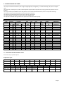
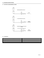
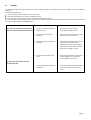
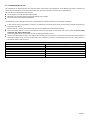
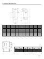
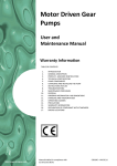
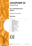
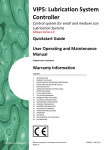
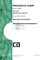
PNEUMATIC PUMP
Series 31030..
User and
Maintenance Manual
Original text translation
Warranty information
TABLE OF CONTENTS
1.
2.
3.
4.
5.
6.
7.
http://www.dropsa.com
INTRODUCTION
DESCRIPTION OF THE PUMP
TECHNICAL SPECIFICATIONS
CORRECT USE
DIMENSIONS
DECLARATION OF CONFORMITY
DISTRIBUTORS
Manual drafted in compliance with
CE Directive 06/42
C2002IE – WK 26/11
1. INTRODUCTION AND WARNING
This user’s and maintenance manual refers to a series 31030 Pneumatically Driven Pump – with light alloy or sheet steel tank, for
use in mineral oil lubrication systems.
It is recommended that this manual is carefully kept in good condition and is always available to persons requiring to consult it.
To request further copies, updates or clarifications with respect to this manual contact the Engineering Department at Dropsa
SpA. or from our website http://www.dropsa.com.
The use of the pump referred to in this manual must be entrusted to qualified personnel with a knowledge of hydraulics and
electrical systems; the non-observance of the information given in this manual or the improper use of the equipment by nonqualified or non-authorised personnel can put persons or the environment at risk due to the escape of fluids under pressure.
It is of extreme importance that the instructions for use are read and understood both by the operators and maintenance
personnel, in cases of doubt please contact the area representative or our “Customer Service” department.
The manufacturer reserves the right to update the product and/or the user’s manual without the obligation to revise previous
versions. It is however, possible to contact the Engineering Department for the latest revision in use.
It is the responsibility of the installer to utilise tubing suitable for the system; the use of unsuitable tubing can generate
problems with the pump, risks to persons and cause pollution.
The loosening of connections can cause serious safety problems and all such connections should be checked before and after
installation and tightened if necessary.
Never exceed the maximum operating pressure values allowed for the pump and the components to which it is connected.
Before any maintenance or cleaning operations, close off the air supply and release the pressure from the pump and the tubing
to which it is connected.
Do not subject the pump, the tubing or other parts under pressure to violent impacts; damaged tubing or connections are
dangerous and should be replaced.
After prolonged periods of inactivity, ensure the tightness of all connections subjected to pressure.
It is required that personnel make use of protection devices, clothing and necessary tools, suitable to the place and employment
of the pump both while in operation and during the undertaking of maintenance tasks.
The pump, and any accessories mounted on it, should be carefully checked immediately on receipt and in the event of any
discrepancy or complaint the Dropsa SpA Sales Department should be contacted without delay
DROPSA S.p.A. declines to accept any responsibility for injuries to persons or damage to property in the event of the nonobservance of the information presented in this manual.
Any modification to component parts of the system or the different destination of use of this system or its parts without prior
written authorisation from DROPSA S.p.A. will absolve the latter from any responsibility for injury or damage to persons and/or
property and will release them from all obligations arising from the guarantee.
Page 2
2. DESCRIPTION OF THE PUMP
The pump is of robust construction, with a high strength light alloy casting body, or a sheet steel body, and a piston in lapped
steel.
The pump unit is made up of a cylinder in which operates a piston with an oilproof seal; a spring returns the piston to its start
position.
The pump must be provided with a three way electrical or mechanical distribution device, that is: line-cylinder-discharge.
The duration of the command impulse must not be less than 3 seconds.
The release (in the discharge position) must not be less than 10 seconds.
The useful capacity means the sum of the values of the applied valves.
The expansion of flexible tubing utilised in the system will reduce the useful capacity.
VERSIONS AVAILABLE WITH CHARACTERISTICS
Part
number
3103010
3103011
3103017
3103049
3103036
3103038
3103001
3103002
3103015
3103018
3103006
3103019
3103029
3103020
3103030
3103025
3103026
3103027
3103149
pressure
c.c./stroke
min.
4
4
4
4
4
4
4
4
4
4
4
4
4
4
4
4
4
4
4
useful
3.5
3.5
3.5
3.5
3.5
3.5
7.5
7.5
7.5
7.5
15
15
15
15
15
3.5
3.5
3.5
3.5
max.
7
7
7
7
7
7
7
7
7
7
7
7
7
7
7
8
8
8
8
tank
max
7.5
7.5
7.5
7.5
7.5
7.5
15
15
15
15
30
30
30
30
30
7.5
7.5
7.5
7.5
syst.
litres
0.8
1.5
6
0.8
6
no
0.4
0.8
1.5
6
1.5
6
1.5
no
no
0.8
1.5
6
0.8
ratio
04
04
04
04
04
04
06
06
06
06
06
06
06
06
06
26
26
26
26
weight
8.5/1
8.5/1
8.5/1
8.5/1
8.5/1
8.5/1
4/1
4/1
4/1
4/1
4/1
4/1
4/1
4/1
4/1
8.5/1
8.5/1
8.5/1
8.5/1
min.
level.
electric
no
yes
yes
yes
yes
no
no
no
yes
yes
no
yes
yes
no
yes
no
yes
yes
no
Kg
1.8
4
8
2
8
1.6
2.26
2.48
4
8
4
8
4
1.6
2
1.8
4
8
1.8
dimensions
lxdxh (mm.)
110x123x253
124x123x390
327x168x335
142x123x296
327x168x335
Diam. 78x142
84x103x253
117x123x253
124x123x390
327x168x340
124x123x343
327x168x340
124x123x390
Diam. 70x175
140x114x290
110x123x253
124x123x390
327x168x335
110x123x243
2.1 ACCESSORIES AND REPLACEMENT PARTS
Accessories as per specific request.
Replacement parts:
MODEL
3103001
3103002
3103006
3103010
3103011
3103015
3103025
3103026
3103029
3103049
Filter - suction
3130062
3130137
3130137
3130137
3130137
3130137
3130137
3130137
3130137
3130137
MODEL
3103017
3103018
3103019
3103027
3103036
Filter - load
3130049
3130049
3130049
3130049
3130049
Filter - suction
3130052
3130052
3130052
3130052
3130052
Filter -load
3103020
3103030
3130137
3130052
3103038
3103149
3130137
Page 3
3. TECHNICAL SPECIFICATIONS
3.1 METHODS OF COMMANDING THE PUMP
Manual push-button control
Supply
Discharge
3-way solenoid valve control
Supply
Discharge
Mechanical roller cam or cam bar
control
Supply
Discharge
3.2 OTHER DATA
Viscosity of the lubricant at working temperature
Working temperature
Working humidity
Preservation temperature
Sound pressure level
Between 15 - 1000 cSt
+ 5 - + 40 C
90 % relative humidity.
- 20 - + 50 °C
< 70 dB(A)
Page 4
4. CORRECT USE
4.1 PUTTING INTO SERVICE
The unit may be used, opened and repaired only by specialised personnel.
The pump MUST NOT be submersed in fluids or utilised in environments which are particularly aggressive or
explosive/inflammable if not prepared for this purpose beforehand by the supplier.
For correct fixing verify the distance between centres shown in the diagram in Section 2.
Use gloves and safety glasses as required in the lubrication oil safety chart
DO NOT use aggressive lubricants with NBR gaskets and seals; if in doubt consult the Engineering Department of Dropsa
SpA, who will provide a chart with the details of recommended oils.
DO NOT ignore dangers to health and observe all hygiene standards.
WARNING! All electrical components must be grounded. This refers to both electrical components and control devices. In
this regard ensure that the ground cable is correctly connected. For reasons of safety the ground cable must be approx.
100 mm longer than the phase cables. In the event of accidental detachment of the cable, the ground terminal must be the
last to be removed.
Action to be taken prior to start up
Verify the integrity of the pump;
Fill the tank with suitable lubricant (min/max indication on the tank);
Verify that the pump is at operating temperature and the tubing free from air bubbles;
Check that the electrical connections have been effected correctly (CEI 64/8, IEC 364);
Verify the correct connections of any level and pressure switches to the control panel
The minimum level indicator is supplied, unless otherwise specified by the customer, with the contact closed for minimum
level. Should the user require to use a normally open contact it will be necessary to open the tank and to invert the
operating direction of the float.
4.2 USE
1.
2.
3.
4.
verify the settings on the control panel, where fitted;
press the start button of the machine to which the pump is connected;
verify the starting of the pump;
verify the adequate lubrication of the machine (if doubt exists as to the correct functioning consult the Engineering
Department of Dropsa SpA to request test procedures).
4.3 TRANSPORT AND STORAGE
Transport and storage is effected in a cardboard package.
No particular precautions are required except as noted on the package itself.
Handling can be effected by one person.
WARNING: Lift the unit with taking account of the right way up indicated on the cardboard carton.
The machine components can withstand temperatures, during storage, from -20 to +50°C; however, in order to
avoid damage, starting of the machine should occur at a minimum temperature of -5°C.
Page 5
4.4 ASSEMBLY/DISASSEMBLY
No pump assembly operations are envisaged.
For wall mounting ensure adequate space is available (as shown in the installation diagram) to avoid abnormal postures and
possible impacts; four fixing holes are provided with different characteristics depending on the version (see section 2.2)
Subsequently it will be necessary, as previously described, to connect the pump to the machine hydraulically and then to
connect the control panel.
During the disassembly phase ensure the tank is empty.
Disconnect the electrical and hydraulic parts.
Where the machine is to be scrapped, do not dispose of potentially polluting parts in the environment, following local
regulations for their correct disposal.
At the time of the machine being scrapped it is necessary to remove and destroy the identification plate and all other relative
documents.
4.5 REGULATION
The only parameter which can be modified is the pressure; to modify the value increase or decrease the pressure of the
command air supply.
4.6 MAINTENANCE
WARNING: Locate the machine in conditions which facilitate easy access.
Utilise individual protection to avoid contact with mineral oil or grease.
Having undergone rigorous testing by ourselves, the pump does not require any further maintenance. The use of lubricants free
from impurities is recommended and the periodic careful cleaning of the component parts of the pump.
Disassembly must be effected in the following manner:
1.
2.
3.
4.
5.
Disconnect the tubing attached to the pump.
Remove the fixing screws and the tank and relative cover.
Remove the suction filter and the relative valve.
Unscrew the cylinder paying particular attention to the loading of the springs; the component parts of the pump unit can
then be disassembled.
Remove the screws which retain the flange so releasing the complete pump unit.
In this way all component parts of the pump unit can be removed allowing the disassembly and cleaning of the release and
suction valves.
All pieces should be washed in petrol and lubricated prior to reassembly.
The following should be checked periodically:
VERIFY
The state of lubrication
The oil level
The cleanliness of the suction filter
That the tank is clean and the bottom free from deposits
WORK CYCLES
100
200
400
600
The machine does not require any special tools to carry out checks or maintenance tasks, However, it is recommended that only
tools suitable for the tasks and in good condition should be utilised (according to current regulation) to avoid injury to persons
or damage to machine parts
Page 6
4.7
REPAIRS
The following diagnostic table indicates the main anomalies which may be encountered, the probable causes and possible
solutions.
The anomalies shown are:
the pump fails to deliver sufficient oil or no oil at all;
the pump fails to deliver oil at the prescribed pressure;
failure to release line pressure (only on systems with volumetric valves).
In case of doubts and/or problems which cannot be resolved do not attempt to disassemble parts of the machine but contact
the Engineering Department of DROPSA S.p.A.
INDICATION
The pump does not deliver oil or does not
deliver oil in the exact quantity prescribed
PROBABLE CAUSE
REMEDY
The oil in the tank is below the
minimum level
Fill the tank with oil without
exceeding the MAX level line
The suction filter is dirty or
blocked
Open the cover of the pump, remove
the suction filter and clean it
The pump control valve fails to
discharge
Check that the pump control valve is a
3-way type and that the valve
regularly discharges compressed air
from the pump pneumatic chamber
when the air supply is cut off.
The internal connections are
loose
Remove the plate from the tank and
carefully tighten all connections
ensuring there are no leaks
The compressed air pressure is
insufficient
Increase the compressed air pressure
to reach the required oil pressure
value
The pump does not deliver oil at the
prescribed pressure
Page 7
4.8 DANGERS PRESENT IN USE
The verification of conformity with the essential safety requirements and regulations of the Machine Directive is effected by
means of the compilation of a check list which has been pre-prepared and is contained in the technical file.
The lists which are utilised are of three types:
List of dangers (as in EN 414 referring to EN 292)
Application of essential safety requirements (Machine Dir. 06/42)
Electrical safety requirements (EN 60204-1)
The following is a list of dangers which have not been fully eliminated but which are considered acceptable:
In the version of the pump without a release it is possible to encounter squirts of oil (for this reason appropriate protective
clothing must be worn)
Contact with oil -> see the requirements for the use of suitable personal protective clothing
Use of unsuitable lubricant -> the characteristics of the fluid are shown on the pump and in the manual (in case of doubt
contact the Eng. Dept of Dropsa Spa)
Protection against direct and indirect contact must be provided by the user
Given the purpose of the pump it must always be functioning; for this reason it is necessary to pay attention to the electrical
connections which, in the case of a power failure, the customer’s machine is restarted only by means of a reset, while the
lubrication pump is able to restart
INADMISSIBLE FLUIDS
Fluids
Lubricants with abrasive additives
Lubricants with silicone based additives
Petrol – solvents – inflammable liquids
Corrosive products
Water
Food substances
Danger
High wear rate of contacted parts
Seizure of the pump
Fire – explosion – damage to seals
Corrosion of the pump– injury to persons
Oxidation of the pump
Contamination of the substances themselves
Page 8
5. DIMENSIONS AND DISTRIBUTORS
Model
3103001
3103002
3103006
3103010
3103011
3103015
3103025
3103026
3103029
3103049
3103149
A
60
93
100
93
100
100
93
100
100
93
93
B
12
12
12
12
12
12
12
12
12
12(+25 man.)
12
C
85
62
132
62
132
132
62
132
132
62
62
Model
3103017
3103018
3103019
3103027
3103036
D
M10x1
M10x1
M14x1,5
M10x1
M14x1,5
M14x1,5
M10x1
M14x1,5
M14x1,5
M10x1
M10x1
A
305
305
305
305
305
E
M10x1
M10x1
M14x1,5
M10x1
M14x1,5
M14x1,5
M10x1
M14x1,5
M14x1,5
M10x1
M10x1
B
335
340
340
335
335
F
110
90
170
90
170
170
90
170
170
90
90
G
253
253
343
253
390
390
253
390
390
253
243
C
205
205
205
205
205
H
106
116
128
116
135
135
116
135
135
116
116
D
327
327
327
327
327
I
44
54
54
54
54
54
54
54
54
54
54
E
168
168
168
168
168
Page 9
6. DECLARATION OF CONFORMITY
Dropsa Spa
Via Benedetto Croce, 1
20090 Vimodrone (MI)
Italy
Tel.:
Fax Sales:
E-mail:
Web site:
(+39) 02. 250.79.1
(+39) 02. 250.79.767
[email protected]
http://www.dropsa.com
DICHIARAZIONE
DI CONFORMITÁ/DECLARATION OF COMPLIANCE WITH STANDARDS/
DECLARATION DE CONFORMITE/ KONFORMITÄTSERKLÄRUNG DES STANDARDS /DECLARACIÓN DE
CONFORMIDAD/ DECLARAÇÃO DE CONFORMIDADE
La società Dropsa S.p.A., con sede legale in Milano, Via Besana,5/ Dropsa S.p.A., registered office in Milan,
Via Besana,5 / Dropsa S.p.A. au Siège Social à Milan, Via Besana,5/ Dropsa S.p.A., Sitz in Milano, Via
Besana 5/ La sociedad Dropsa S.p.a., con sede legal en Milán, Via Besana,5/ A Dropsa S.p.A, com sede em
Milão, via Besana, nº 5
DICHIARA /CERTIFIES / CERTIFIE/ ZERTIFIZIERT, DASS/ DECLARA/ CERTIFICA:
che la macchina denominata/that the machine named / que la machine dénommée/ Die Maschine mit
der Bezeichnung/ que la máquina denominada/ que o equipamento denominado
POMPE A COMANDO PNEUMATICO SERIE 31030
è conforme alle condizioni previste dalle Direttive CEE /has been constructed in conformity with the
Directives Of The Council Of The European Community on the standardization of the legislations of
member states/ a été construite en conformité avec les Directives Du Conseil Des Communautes
Europeennes/ Entsprechend den Richtlinien des Rates Der Europäischen Union, für die Standarisierung
der Legislative der Mitgliederstaaten, konstruiert wurde/ cumple con las condiciones establecidas por las
directivas comunitarias/ foi construído em conformidade com as diretivas do Conselho das Comunidades
Europeias:
2006/42 Direttiva macchine /Machinery Directive / 2006/42 Directive machines / Maschinenrichtlinien/
Maquinaria 2006/42/CEE /Directiva 2006/42 Máquinas;
Vimodrone (MI), June 2011
Technical Director:
Maurizio Greco
…………………………
Legal representative
Milena Gavazzi
…………………………
Page 10
7. DISTRIBUTORS
Dropsa S.p.A.
Via B. Croce,1
20090 Vimodrone (MI) Italy.
Tel: (+39) 02 - 250.79.1
Fax: (+39) 02 - 250.79.767
E-mail: [email protected] (Export)
E-mail: [email protected] (National)
Dropsa Ame
23, Av.des.Morillons
Z.I. des Doucettes 91140
Garges Les Gonesse, France
Tel: (+33) 01 39 93 00 33
Fax: (+33) 01 39 86 26 36
E-mail: [email protected]
Dropsa (UK) Ltd
Unit 6, Egham Business Village,
Egham,Surrey,TW20 8RB
Tel: (+44) 01784 - 431177
Fax: (+44) 01784 - 438598
E-mail: [email protected]
Dropsa do Brazil Ind. E Com. Ltda
Rua Sobralia 175,
Sao Paulo, Brazil
Tel: (+55) 011-5631-0007
Fax: (+55) 011-5631-9408
E-mail: [email protected]
Dropsa USA Inc.
6645 Burroughs Ave
48314-2132 Srerling Hts,Mi Us -USA
Tel: (+1) 586-566-1540
Fax: (+1) 586-566-1541
E-mail: [email protected]
Dropsa Lubrication Systems
Nr 8 Dongxing Road,
Songjiang Industrial Zone
(Shanghai) Co., Ltd
Tel: +86 (021) 67740275
Fax: +86 (021) 67740205
E-mail: [email protected]
Dropsa Gmbh
Volmerswerther Strasse 80
40221 Dusseldorf 1, Deutschland
Tel: (+49) 0211/39 4011
Fax:(+49) 0211/39 4013
E-mail: [email protected]
Dropsa Australia Pty.
C20/148 Old Pittwater Road
Brookvale, NSW 2100
Tel: +61 (02) 9938 6644
Fax: +61 (02) 99 386 611
E-mail: [email protected]
Web site: http://www.dropsa.com - E-mail: [email protected]
Page 11