1
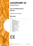
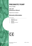
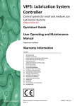
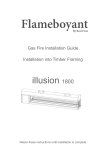
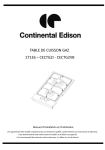
PNEUMATIC PUMP Series 3103... User and Maintenance Manual Original text translation Warranty information TABLE OF CONTENTS 1. 2. 3. 4. 5. 6. 7. 8. 9. 10. 11. 12. 13. 14. 15. 16. 17. 18. http://www.dropsa.com INTRODUCTION GENERAL DESCRIPTION PRODUCT-MACHINE IDENTIFICATION TECHNICAL CHARACTERISTICS PUMP COMPONENTS UNPACKING AND INSTALLING THE PUMP PUMP OPERATIONS TROUBLESHOOTING MAINTENANCE PROCEDURE DISPOSAL ORDERING INFORMATION DIMENSIONS HANDLING AND TRASPORTATION OPERATING HAZARDS PRECAUTIONS WARRANTY INFORMATION DECLARATION OF COMPLIANCE WITH STANDARDS DROPSA LOCATIONS Manual drafted in compliance with CE Directive 06/42 C2039IE – WK 27/11 1. INTRODUCTION This manual refers to the Pneumatic Pump Series 3103... You can find additional copies and newer revisions of this document from our website http://www.dropsa.com. Alternatively contact one of our Sale Offices. Please read this manual carefully, as it contains important information on health safety issues: a copy of this manual should remain with the user of the product. 2. GENERAL DESCRIPTION Pneumatic Pump Series 3103...is characterized by an optimal relation price/performance, small dimensions, long lasting life. It is recommended for all the applications on textile, glass making and plate deforming machines. Compatible with Serial 26 Systems and Valve 33. The pump allows a 3-second working-time and a 10-second pause-time depending on lubricant viscosity. Pump control unit consists of a cylinder in which an anti-oil rubber seal runs. A spring ensures piston-return to the starting position. The solenoid valve control must be 3-way, normally closed (N.C.) 3. PRODUCT – MACHINE IDENTIFICATION Pump identification label is located on the front side of the reservoir containing pump serial number and details of its operating parameters. 4. TECHNICAL CHARACTERISTICS Operating temperature Maximum operating humidity Flowrate* Maximum pressure Control air pressure Compression ratio Cycle minimum time Pause minimum time Reservoir capacity Return oil filter Lubricant Viscosity at working temperature PNEUMATIC PUMP Series 3103... -5 °C ÷ +40 °C (+23 °F ÷ +104 °F) 90% relative humidity 2.6 cm3/stroke (0.158 cu.in./stroke) 68 bar (1000 psi) 3 ÷ 8 bar (43 ÷ 116 psi) 8.5: 1 3 seconds 10 seconds 3 litres (0.66 galls) Paper + metallic + magnet Mineral oil 15 ÷ 1000 cSt (77.31 ÷ 4628 SUS) * The effective flowrate is given by the sum of the value of the applied valves, which cannot exceed 50% of the pump nominal value WARNING: The expansion of the flexible hoses causes a decrease of the usable flowrate. 2 5. PUMP COMPONENTS Pump main component is the baseplate on which pump components are fixed. The reservoir is made of light-coloured Moplen which allows to check oil level. Pneumatic pump air inlet and lubricant outlet are both located on the baseplate. The re-circulating oil filter, needed for all the applications involving oil recycling, is supplied with four inlets. one or more inlet (depend on the version) The Samba sensor level indicates the minimum level achievement through an electric contact closure. Air inlet pump control Lubricant outlet Refilling plug Board connection Min. level and pressure switch Recirculating oil filter Loading filter Tank Pneumatic pump (Seal spare parts 3132535) 3 6. UNPACKING AND INSTALLING THE PUMP WARNING: The unit must be used, opened and repaired only by qualified personnel. 6.1 UNPACKING Once a suitable location has been found to install the unit remove the pump from the packaging. Check the pump has not been damaged during transportation or storage. No particular disposal procedures are necessary, however packing should be disposed of in accordance with regulations that may be in force in your area or state. 6.2 INSTALLING THE PUMP No particular assembly pump operations are provided. Allow sufficient space for the installation, leaving minimum 100 mm (3.93 in.) around the pump in order to avoid unnatural posture or possibility of sustaining impacts. Do not install the pump plunged into fluids or in aggressive/explosive/inflammable environments, if not preventively provided for this purpose by the supplier. For correct fixing, verify the distance between centres shown in the diagram, ch. 12. Use gloves and safety glasses as required in the lubrication oil safety chart . DO NOT use aggressive lubricants with NBR seals. For any doubt, please consult the Engineering Department of Dropsa S.p.A., that will provide a detailed chart of recommended oils. 6.3 HYDRAULIC FITTING The pump is connected to the system by means of a hydraulic fitting located on the baseplate and coming from the pump. Piping must be nylon Ø4 mm (Ø 0.15 in.) (furnishable by Dropsa). 6.4 PNEUMATIC FITTING Connect the solenoid valve air control inlet pipe to the fitting, using a Ø4 mm (Ø 0.15 in.) nylon pipe and arrange a check valve to stop lubricant supply, when required. 6.5 ELECTRIC WIRING Electronic board on the pump is the only electric wiring required. The board in Figure 1 (cod. 1639183), is predisposed in order to receive a 4 poles “AMP MODU II 280359-0” connector , or a 4 poles “MINIFIT JR RECEPTACLE 39-01-3048” connector. 4 7. PUMP OPERATIONS 7.1 COMMISSIONING THE PUMP Refill the reservoir with compatible lubricant. Connect the pump to a treated compressed air source. Start the pump and verify its correct operation. 7.2 PUMP CONTROLS L u b rican t su p p ly Push-button hand control: Pump D isch arg e L u b rican t su p p ly 3-way solenoid valve control: Pump D isch arg e L u b rican t su p p ly Circular or rectilinear cam drive: Pump D isch arg e 7.3 PRESSURE SETTING It is possible to adjust lubricant outlet pressure by regulating the inlet air pressure. 7.4 RESERVOIR REFILLING Use compatible lubricant and refill the reservoir through the oil refilling plug with a filter. Do not pour lubricant directly into the reservoir. 7.5 AIR DISCHARGE Air in the system does not affect pump well-functioning. However, it is advisable to discharge air by starting the pump until lubricant comes out air-bubbles-free. WARNING: any presence of air in the system could lower nominal flow. 5 8. TROUBLESHOOTING The following diagnostic table indicates the main anomalies which may be encountered, the probable causes and possible solutions. If you cannot solve the problem, do not attempt to disassemble parts of the machine but contact the Engineering Department of DROPSA S.p.A. ANOMALY Pump does not deliver oil at all or the fixed quantity Pump delivers oil at an improper pressure PROBABLE CAUSE SOLUTION Fill up the reservoir with impurity-free lubricant. Oil level in the reservoir lower WARNING: if the reservoir is empty but no than the minimum minimum level is shown, please check the level contact Disassemble the pump from the reservoir, remove and Suction valve filter unclean or wash the inlet valve; if this procedure is insufficient, obstructed replace the valve Verify that pump control valve is 3-way and that it Pump control valve does not discharges compressed air in the pump pneumatic discharge chamber at the end of the cycle Disassemble the pump from the reservoir, remove and Pressure vent valve does not wash the pressure vent valve; if this procedure is discharge insufficient, replace the valve Disassemble the baseplate from the reservoir and carefully Loosened inner fittings retighten all the fittings. Be sure there are no leakages Piston failure Replace the pumping unit Wrong adjustment of the control air pressure Adjust carefully the air pressure in accordance with the technical characteristics, considering a compression ratio of 8.5:1 9. MAINTENANCE PROCEDURE Pump has been designed and constructed to require a minimum maintenance. For an easy maintenance, it is advised to assemble the pump in a comfortable and reachable location. The machine does not require any special tool for check or maintenance tasks. However, it is recommended the use only of appropriate and in good conditions tooling, protective devices (gloves) and clothing (according to current regulation) to avoid injury to persons or damage to machine parts. Periodically check the pipe joints to detect possible leaks. Furthermore, keep the machine unit clear to readily detect possible leaks. Replace the refilling filter and the re-circulating filter, when required. The use of impurity-free lubricant is recommended. Disassemble the pumping unit as follows: 1. Remove piping from the pump. Be sure there are no residual pressure in the system. 2. Unscrew baseplate fixing screws and reservoir screws. 3. Remove pump and filters. 4. Unscrew pump cylinder paying attention to the spring charge; then remove pumping unit parts. When all pump components are dismantled, it is possible to disassemble and to clean the release and suction valves. Before the reassembling, wash and lubricate all pump components. 6 Filters replacing: Replace the refilling and the recirculating filters by simply unscrewing the fastening screws and extracting the filter(s) from the top. It is recommended a periodical maintenance as follows: Inspection Lubricant checking Refilling filter cleaning Recirculating filter cleaning Reservoir bottom cleaning in case of impurities Number of work cycles 10000 25000 25000 30000 Prior to any maintenance, be sure that the power, hydraulic and pneumatic supplies are off. 10. DISPOSAL During maintenance or disposal of the machine care should be taken to properly dispose of environmentally sensitive items. Refer to local regulations in force in your area. When disposing of this unit, it is important to ensure that the identification label and all the other relative documents are also destroyed. 11. ORDERING INFORMATION STANDARD VERSIONS PART NUMBER 3103269 3103289 DESCRIPTION Pneumatic pump 2.6 cc/stroke (0.15 cu.in./stroke) without manifold Pneumatic pump 2.6 cc/stroke (0.15 cu.in./stroke) without manifold and without return For ordering codes contact Dropsa technical / sales office. SPARE PARTS PART NUMBER 3130355 3130101 6770070 3092110 3132535 3103117 6770054 3050585 1655583 1655582 1655590 DESCRIPTION Recirculating filter Refilling filter Oil pouring clicking plug Suction valve Seal pneumatic pump kit Pneumatic pump 2.6 cc/stroke (0.15 cu.in./stroke), ratio 8.5:1 3 litres (0.66 galls) reservoir Baseplate “Samba” level NC “Samba” level NA “Samba” level NA or NC ACCESSORIES PART NUMBER 0045351 0045275 0045350 0045274 DESCRIPTION Solenoid 3/2 NC 24V Dc Solenoid 3/2 NC 24V Ac 50 Hz Solenoid 3/2 NC 110V Ac 50 Hz Solenoid 3/2 NC 230V Ac 50 Hz 7 12. DIMENSIONS 13. HANDLING AND TRANSPORTATION Due to pump low weight (~2.5 kg dry) and small dimensions, it is not necessary the use of material handling equipment. Prior to shipping, pump is carefully packed in a cardboard packing. During pump transportation and storage, pay attention to the side on the cardboard packing. On receipt, check that the packing is not damaged. Then, storage the pump in a dry location. Lift the equipment observing the right way up shown on the cardboard packing. During storage, machine components can withstand temperatures –20 °C ÷ +50 °C (-4 °F ÷ +122 F°). However, in order to avoid damages, machine starting should occur at a minimum temperature of +5 °C (+41 °F). 8 14. OPERATING HAZARDS It is necessary to carefully read about the instructions and the risks involved in the use of lubrication machines. The operator must know the machine functioning through the user manual. Power supply Any type of intervention must not be carried out before the unplugging of the machine from power supply. Make sure that no one can start it up again during the intervention. All the installed electric and electronic equipment, reservoirs and basic components must be grounded. Inflammability The lubricant generally used in lubrication systems is not normally inflammable. However, it is advised to avoid contact with extremely hot substances or naked flames. Pressure Prior to any intervention, check the absence of residual pressure in any branch of the lubricant circuit as it may cause oil sprays when disassembling components or fittings. Noise Pump does not produce excessive noise, less than 70 dB(A) . 15. PRECAUTIONS No particular operating hazards characterize Pneumatic Pump Series 3103..., except for the following precautions: Operator’s contact with fluid in case of piping breaking/opening or contact with oil during filling up/maintenance. The operator must be provided with suitable personal protective clothing. Unnatural posture. Use of incompatible lubricant. Main unauthorized fluids: Fluids Lubricants containing abrasive components Lubricants containing silicon Petrol – solvents – inflammable liquids Corrosive products Water Food Products Dangers Premature wear of pump Pump failure Fire – explosion –seal damage Pump damage - danger to persons Pump oxidization Contamination of the product 9 16. WARRANTY INFORMATION All products manufactured and marketed by Dropsa are warranted to be free of defects in material or workmanship for a period of at least 12 months from date of delivery. Extended warranty coverage applies as follows: Complete system installation by Dropsa: 24 Months All other components: 12 months from date of installation; if installed 6 months or more after ship date, warranty shall be maximum of 18 months from ship date. If a fault develops, notify us giving a complete description of the alleged malfunction. Include the part number(s), test record number where available (format xxxxxx-xxxxxx), date of delivery and installation and operating conditions of subject product(s). We will subsequently review this information and, at our option, supply you with either servicing data or shipping instruction and returned materials authorization (RMA) which will have instructions on how to prepare the product for return. Upon prepaid receipt of subject product to an authorized Dropsa Sales & Service location, we will then either repair or replace such product(s), at out option, and if determined to be a warranted defect, we will perform such necessary product repairs or replace such product(s) at our expense. Dropsa reserves to right to charge an administration fee if the product(s) returned are found to be not defective. This limited warranty does not cover any products, damages or injuries resulting from misuse, neglect, normal expected wear, chemically caused corrosion, improper installation or operation contrary to factory recommendation. Nor does it cover equipment that has been modified, tampered with or altered without authorization. Consumables and perishable products are excluded from this or any other warranty. No other extended liabilities are states or implied and this warranty in no event covers incidental or consequential damages, injuries or costs resulting from any such defective product(s). The use of Dropsa product(s) implies the acceptance of our warranty conditions. Modifications to our standard warranty must be in made in writing and approved by Dropsa. 10 17. DECLARATION OF COMPLIANCE WITH CE STANDARDS Dropsa Spa Via Benedetto Croce, 1 20090 Vimodrone (MI) Italy Tel.: Fax Sales: E-mail: Web site: (+39) 02. 250.79.1 (+39) 02. 250.79.767 [email protected] http://www.dropsa.com DICHIARAZIONE DI CONFORMITÁ/DECLARATION OF COMPLIANCE WITH STANDARDS/ DECLARATION DE CONFORMITE/ KONFORMITÄTSERKLÄRUNG DES STANDARDS /DECLARACIÓN DE CONFORMIDAD/ DECLARAÇÃO DE CONFORMIDADE La società Dropsa S.p.A., con sede legale in Milano, Via Besana,5/ Dropsa S.p.A., registered office in Milan, Via Besana,5 / Dropsa S.p.A. au Siège Social à Milan, Via Besana,5/ Dropsa S.p.A., Sitz in Milano, Via Besana 5/ La sociedad Dropsa S.p.a., con sede legal en Milán, Via Besana,5/ A Dropsa S.p.A, com sede em Milão, via Besana, nº 5 DICHIARA /CERTIFIES / CERTIFIE/ ZERTIFIZIERT, DASS/ DECLARA/ CERTIFICA: che la macchina denominata/that the machine named / que la machine dénommée/ Die Maschine mit der Bezeichnung/ que la máquina denominada/ que o equipamento denominado PNEUMATIC PUMP SERIES 3103... è conforme alle condizioni previste dalle Direttive CEE /has been constructed in conformity with the Directives Of The Council Of The European Community on the standardization of the legislations of member states/ a été construite en conformité avec les Directives Du Conseil Des Communautes Europeennes/ Entsprechend den Richtlinien des Rates Der Europäischen Union, für die Standarisierung der Legislative der Mitgliederstaaten, konstruiert wurde/ cumple con las condiciones establecidas por las directivas comunitarias/ foi construído em conformidade com as diretivas do Conselho das Comunidades Europeias: 2006/42 Direttiva macchine /Machinery Directive / 2006/42 Directive machines / Maschinenrichtlinien/ Maquinaria 2006/42/CEE /Directiva 2006/42 Máquinas; Vimodrone (MI), July 2011 Technical Director: Maurizio Greco ………………………… Legal representative Milena Gavazzi ………………………… 11 18. DROPSA LOCATIONS Dropsa S.p.A. Via B. Croce,1 20090 Vimodrone (MI) Italy. Tel: (+39) 02 - 250.79.1 Fax: (+39) 02 - 250.79.767 E-mail: [email protected] (Export) E-mail: [email protected] (National) Dropsa Ame 23, Av.des.Morillons Z.I. des Doucettes 91140 Garges Les Gonesse, France Tel: (+33) 01 39 93 00 33 Fax: (+33) 01 39 86 26 36 E-mail: [email protected] Dropsa (UK) Ltd Unit 6, Egham Business Village, Egham,Surrey,TW20 8RB Tel: (+44) 01784 - 431177 Fax: (+44) 01784 - 438598 E-mail: [email protected] Dropsa do Brazil Ind. E Com. Ltda Rua Sobralia 175, Sao Paulo, Brazil Tel: (+55) 011-5631-0007 Fax: (+55) 011-5631-9408 E-mail: [email protected] Dropsa USA Inc. 6645 Burroughs Ave 48314-2132 Srerling Hts,Mi Us -USA Tel: (+1) 586-566-1540 Fax: (+1) 586-566-1541 E-mail: [email protected] Dropsa Lubrication Systems Nr 8 Dongxing Road, Songjiang Industrial Zone (Shanghai) Co., Ltd Tel: +86 (021) 67740275 Fax: +86 (021) 67740205 E-mail: [email protected] Dropsa Gmbh Volmerswerther Strasse 80 40221 Dusseldorf 1, Deutschland Tel: (+49) 0211/39 4011 Fax:(+49) 0211/39 4013 E-mail: [email protected] Dropsa Australia Pty. C20/148 Old Pittwater Road Brookvale, NSW 2100 Tel: +61 (02) 9938 6644 Fax: +61 (02) 99 386 611 E-mail: [email protected] Web site: http://www.dropsa.com - E-mail: [email protected] 12