1
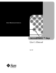
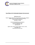
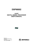
MIPS R10000 Microprocessor
User’s Manual
Version 2.0
viii
Table of Contents
1
Introduction to the R10000 Processor
MIPS Instruction Set Architecture (ISA) .....................................................................................2
What is a Superscalar Processor? .................................................................................................3
Pipeline and Superpipeline Architecture..........................................................................3
Superscalar Architecture .....................................................................................................3
What is an R10000 Microprocessor? ............................................................................................4
R10000 Superscalar Pipeline ...............................................................................................5
Instruction Queues ...............................................................................................................6
Execution Pipelines ..............................................................................................................6
64-bit Integer ALU Pipeline ......................................................................................6
Load/Store Pipeline...................................................................................................7
64-bit Floating-Point Pipeline ...................................................................................7
Functional Units ...................................................................................................................9
Primary Instruction Cache (I-cache) ..................................................................................9
Primary Data Cache (D-cache) ...........................................................................................9
Instruction Decode And Rename Unit ..............................................................................10
Branch Unit ...........................................................................................................................10
External Interfaces................................................................................................................10
Instruction Queues .........................................................................................................................11
Integer Queue .......................................................................................................................11
Floating-Point Queue...........................................................................................................11
Address Queue .....................................................................................................................12
Program Order and Dependencies ..............................................................................................13
Instruction Dependencies....................................................................................................13
Execution Order and Stalling .............................................................................................13
Branch Prediction and Speculative Execution .................................................................14
Resolving Operand Dependencies.....................................................................................14
Resolving Exception Dependencies...................................................................................15
Strong Ordering....................................................................................................................15
An Example of Strong Ordering ..............................................................................16
R10000 Pipelines .............................................................................................................................17
Stage 1 ....................................................................................................................................17
Stage 2 ....................................................................................................................................17
Stage 3 ....................................................................................................................................18
Stages 4-6 ...............................................................................................................................18
Floating-Point Multiplier (3-stage Pipeline)...........................................................18
Floating-Point Divide and Square-Root Units .......................................................18
Floating-Point Adder (3-stage Pipeline) .................................................................18
Integer ALU1 (1-stage Pipeline)...............................................................................18
Integer ALU2 (1-stage Pipeline)...............................................................................18
Address Calculation and Translation in the TLB ..................................................19
Implications of R10000 Microarchitecture on Software............................................................20
Version 2.0 of October 10, 1996
MIPS R10000 Microprocessor User's Manual
1.
Introduction to the R10000 Processor
This user’s manual describes the R10000 superscalar microprocessor for the system
designer, paying special attention to the external interface and the transfer
protocols.
This chapter describes the following:
•
MIPS ISA
•
what makes a generic superscalar microprocessor
•
specifics of the R10000 superscalar microprocessor
•
implementation-specific CPU instructions
MIPS R10000 Microprocessor User's Manual
Version 2.0 of October 10, 1996
1
2
Chapter 1.
1.1 MIPS Instruction Set Architecture (ISA)
MIPS has defined an instruction set architecture (ISA), implemented in the
following sets of CPU designs:
•
MIPS I, implemented in the R2000 and R3000
•
MIPS II, implemented in the R6000
•
MIPS III, implemented in the R4400
•
MIPS IV, implemented in the R8000 and R10000
The original MIPS I CPU ISA has been extended forward three times, as shown in
Figure 1-1; each extension is backward compatible. The ISA extensions are
inclusive; each new architecture level (or version) includes the former levels.†
MIPS I
MIPS II
MIPS III
MIPS IV
Figure 1-1
MIPS ISA with Extensions
The practical result is that a processor implementing MIPS IV is also able to run
MIPS I, MIPS II, or MIPS III binary programs without change.
† For more ISA information, please refer to the MIPS IV Instruction Set Architecture,
published by MIPS Technologies, and written by Charles Price. Contact information
is provided both in the Preface, and inside the front cover, of this manual.
Version 2.0 of October 10, 1996
MIPS R10000 Microprocessor User's Manual
Introduction to the R10000 Processor
3
1.2 What is a Superscalar Processor?
A superscalar processor is one that can fetch, execute and complete more than one
instruction in parallel.
Pipeline and Superpipeline Architecture
Previous MIPS processors had linear pipeline architectures; an example of such a
linear pipeline is the R4400 superpipeline, shown in Figure 1-2. In the R4400
superpipeline architecture, an instruction is executed each cycle of the pipeline
clock (PCycle), or each pipe stage.
1 Pipe
Stage
Instruction 4
1 PCycle
IF
IS
RF
EX
DF
DS
TC
WB
Instruction 3
IF
IS
RF
EX
DF
DS
TC
WB
IF
IS
RF
EX
DF
DS
TC
WB
IF
IS
RF
EX
DF
DS
TC
Instruction 2
Instruction 1
Figure 1-2
WB
R4400 Pipeline
Superscalar Architecture
The structure of 4-way superscalar pipeline is shown in Figure 1-3. At each stage,
four instructions are handled in parallel. Note that there is only one EX stage for
integers.
Instruction 1
IF
ID
IS
EX
WB
IF = instruction fetch
Instruction 2
IF
ID
IS
EX
WB
ID = instruction decode and dependency
Instruction 3
IF
ID
IS
EX
WB
Instruction 4
IF
ID
IS
EX
WB
Instruction 5
IF
ID
IS
EX
WB
Instruction 6
IF
ID
IS
EX
WB
Instruction 7
IF
ID
IS
EX
WB
Instruction 8
IF
ID
IS
EX
WB
IS = instruction issue
EX = execution (1 only)
Figure 1-3
MIPS R10000 Microprocessor User's Manual
WB = write back
4-Way Superscalar Pipeline
Version 2.0 of October 10, 1996
4
Chapter 1.
1.3 What is an R10000 Microprocessor?
The R10000 processor is a single-chip superscalar RISC microprocessor that is a
follow-on to the MIPS RISC processor family that includes, chronologically, the
R2000, R3000, R6000, R4400, and R8000.
The R10000 processor uses the MIPS ANDES architecture, or Architecture with Nonsequential Dynamic Execution Scheduling.
The R10000 processor has the following major features (terms in bold are defined
in the Glossary):
•
it implements the 64-bit MIPS IV instruction set architecture (ISA)
•
it can decode four instructions each pipeline cycle, appending them to
one of three instruction queues
•
it has five execution pipelines connected to separate internal integer and
floating-point execution (or functional) units
•
it uses dynamic instruction scheduling and out-of-order execution
•
it uses speculative instruction issue (also termed “speculative
branching”)
•
it uses a precise exception model (exceptions can be traced back to the
instruction that caused them)
•
it uses non-blocking caches
•
it has separate on-chip 32-Kbyte primary instruction and data caches
•
it has individually-optimized secondary cache and System interface
ports
•
it has an internal controller for the external secondary cache
•
it has an internal System interface controller with multiprocessor
support
Errata
The R10000 processor is implemented using 0.35-micron CMOS VLSI circuitry on
a single 17 mm-by-18 mm chip that contains about 6.7 million transistors,
including about 4.4 million transistors in its primary caches.
Version 2.0 of October 10, 1996
MIPS R10000 Microprocessor User's Manual
Introduction to the R10000 Processor
5
R10000 Superscalar Pipeline
The R10000 superscalar processor fetches and decodes four instructions in parallel
each cycle (or pipeline stage). Each pipeline includes stages for fetching (stage 1
in Figure 1-4), decoding (stage 2) issuing instructions (stage 3), reading register
operands (stage 3), executing instructions (stages 4 through 6), and storing results
(stage 7).
7 Pipeline Stages
Stage 1
Fetch
Stage 3
Issue
Stage 2
Decode
FP Add Pipeline
Issue
Issue
(FP Queue)
FP Multiply Pipeline
(FP Queue)
5
Execution
Pipelines
Integer ALU Pipeline
(Integer Queue)
Integer ALU Pipeline
(Integer Queue)
Load/Store Pipeline
(Address Queue)
Primary
Instruction
Instruction
Cache
Cache
Stage 5
Execute
Stage 6
Execute
FAdd
FAdd--11
FAdd
FAdd--22
FAdd
FAdd--33
FMpy
FMpy- -22
Stage 7
Store
Result
Result
Floating-Point Queue
and Registers
RF
RF
FMpy
FMpy-1-1
Issue
Issue
RF
RF
ALU1
ALU1
Result
Result
Issue
Issue
RF
RF
ALU2
ALU2
Result
Result
Integer Register Operands
Issue
Issue
RF
RF
.
Addr.Calc
Addr.Calc.
Result
Data
DataCache
Cache Result
TLB
TLB
2-way Interleaved Cache
Read operands from Floating-Point
or Integer Register Files
FMpy
FMpy- -33
Result
Result
Issue
Issue
Queues
Instruction Fetch Pipeline
RF
RF
Stage 4
Execute
Translation-Lookaside Buffer
Decode
Decode
-------Branch Unit
4 Instruction/Cycle Fetch and Decode
Figure 1-4
MIPS R10000 Microprocessor User's Manual
Branch Address (one branch can be handled each cycle)
Functional Units (Execute Instruction)
Superscalar Pipeline Architecture in the R10000
Version 2.0 of October 10, 1996
6
Chapter 1.
Instruction Queues
As shown in Figure 1-4, each instruction decoded in stage 2 is appended to one of
three instruction queues:
•
integer queue
•
address queue
•
floating-point queue
Execution Pipelines
The three instruction queues can issue (see the Glossary for a definition of issue)
one new instruction per cycle to each of the five execution pipelines:
•
the integer queue issues instructions to the two integer ALU pipelines
•
the address queue issues one instruction to the Load/Store Unit
pipeline
•
the floating-point queue issues instructions to the floating-point adder
and multiplier pipelines
A sixth pipeline, the fetch pipeline, reads and decodes instructions from the
instruction cache.
64-bit Integer ALU Pipeline
The 64-bit integer pipeline has the following characteristics:
•
it has a 16-entry integer instruction queue that dynamically issues
instructions
•
it has a 64-bit 64-location integer physical register file, with seven read
and three write ports (32 logical registers; see register renaming in the
Glossary)
•
it has two 64-bit arithmetic logic units:
- ALU1 contains an arithmetic-logic unit, shifter, and integer
branch comparator
- ALU2 contains an arithmetic-logic unit, integer multiplier, and
divider
Version 2.0 of October 10, 1996
MIPS R10000 Microprocessor User's Manual
Introduction to the R10000 Processor
7
Load/Store Pipeline
The load/store pipeline has the following characteristics:
•
it has a 16-entry address queue that dynamically issues instructions,
and uses the integer register file for base and index registers
•
it has a 16-entry address stack for use by non-blocking loads and
stores
•
it has a 44-bit virtual address calculation unit
•
it has a 64-entry fully associative Translation-Lookaside Buffer (TLB),
which converts virtual addresses to physical addresses, using a 40-bit
physical address. Each entry maps two pages, with sizes ranging from
4 Kbytes to 16 Mbytes, in powers of 4.
64-bit Floating-Point Pipeline
The 64-bit floating-point pipeline has the following characteristics:
•
it has a 16-entry instruction queue, with dynamic issue
•
it has a 64-bit 64-location floating-point physical register file, with five
read and three write ports (32 logical registers)
•
it has a 64-bit parallel multiply unit (3-cycle pipeline with 2-cycle
latency) which also performs move instructions
•
it has a 64-bit add unit (3-cycle pipeline with 2-cycle latency) which
handles addition, subtraction, and miscellaneous floating-point
operations
•
it has separate 64-bit divide and square-root units which can operate
concurrently (these units share their issue and completion logic with
the floating-point multiplier)
A block diagram of the processor and its interfaces is shown in Figure 1-5,
followed by a description of its major logical blocks.
MIPS R10000 Microprocessor User's Manual
Version 2.0 of October 10, 1996
Chapter 1.
Secondary Cache
System Interface
Secondary Cache Ctlr
128-bit refill
128-bit refill or writeback
Data Cache
32 Kbytes
2-way Set Associative
32 Kbytes
2-way Set Associative
2 Banks
8-word blocks
16-word blocks
Unaligned access
Addr Four 32-bit instr. fetch
Addr
FP
Queue
64 Integer
Registers
Data
128+10
Secondary Cache
(512 Kbytes to 16 Mbytes)
Synchronous Static RAM
TLB
(4-Mbyte cache requires
ten 256Kx18-bit
RAM chips)
Adr.Calc.
ALU1
ALU2
64 Flt.Pt.
Registers
Branch Unit
Instruction Decode
Register Mapping
Integer
Queue
Tag
64-bit load or store
Switch
Address
Queue
SC Address
19+way
26+7
Instruction Cache
Clocks
System Bus: 64-bit data, 8-bit check, 12-bit command
Up to 4 R10000 Microprocessors may be directly connected.
External Agent
or Cluster Coordinator
Edge of Known World
8
Adder
Multiplier
R10000
Figure 1-5
Version 2.0 of October 10, 1996
Block Diagram of the R10000 Processor
MIPS R10000 Microprocessor User's Manual
Introduction to the R10000 Processor
9
Functional Units
The five execution pipelines allow overlapped instruction execution by issuing
instructions to the following five functional units:
•
two integer ALUs (ALU1 and ALU2)
•
the Load/Store unit (address calculate)
•
the floating-point adder
•
the floating-point multiplier
There are also three “iterative” units to compute more complex results:
•
Integer multiply and divide operations are performed by an Integer
Multiply/Divide execution unit; these instructions are issued to ALU2.
ALU2 remains busy for the duration of the divide.
•
Floating-point divides are performed by the Divide execution unit;
these instructions are issued to the floating-point multiplier.
•
Floating-point square root are performed by the Square-root execution
unit; these instructions are issued to the floating-point multiplier.
Primary Instruction Cache (I-cache)
The primary instruction cache has the following characteristics:
•
it contains 32 Kbytes, organized into 16-word blocks, is 2-way set
associative, using a least-recently used (LRU) replacement algorithm
•
it reads four consecutive instructions per cycle, beginning on any
word boundary within a cache block, but cannot fetch across a block
boundary.
•
its instructions are predecoded, its fields are rearranged, and a 4-bit
unit select code is appended
•
it checks parity on each word
•
it permits non-blocking instruction fetch
Primary Data Cache (D-cache)
The primary data cache has the following characteristics:
•
it has two interleaved arrays (two 16 Kbyte ways)
•
it contains 32 Kbytes, organized into 8-word blocks, is 2-way set
associative, using an LRU replacement algorithm.
•
it handles 64-bit load/store operations
•
it handles 128-bit refill or write-back operations
•
it permits non-blocking loads and stores
•
it checks parity on each byte
MIPS R10000 Microprocessor User's Manual
Version 2.0 of October 10, 1996
10
Chapter 1.
Instruction Decode And Rename Unit
The instruction decode and rename unit has the following characteristics:
•
it processes 4 instructions in parallel
•
it replaces logical register numbers with physical register numbers
(register renaming)
- it maps integer registers into a 33-word-by-6-bit mapping table
that has 4 write and 12 read ports
- it maps floating-point registers into a 32-word-by-6-bit mapping
table that has 4 write and 16 read ports
•
it has a 32-entry active list of all instructions within the pipeline.
Branch Unit
The branch unit has the following characteristics:
•
it allows one branch per cycle
•
conditional branches can be executed speculatively, up to 4-deep
•
it has a 44-bit adder to compute branch addresses
•
it has a 4-quadword branch-resume buffer, used for reversing
mispredicted speculatively-taken branches
•
the Branch Return Cache contains four instructions following a
subroutine call, for rapid use when returning from leaf subroutines
•
it has program trace RAM that stores the program counter for each
instruction in the pipeline
Errata
External Interfaces
The external interfaces have the following characteristics:
•
a 64-bit System interface allows direct-connection for 2-way to
4-way multiprocessor systems. 8-bit ECC Error Check and Correction
is made on address and data transfers.
•
a secondary cache interface with 128-bit data path and tag fields. 9-bit
ECC Error Check and Correction is made on data quadwords, 7-bit
ECC is made on tag words. It allows connection to an external
secondary cache that can range from 512 Kbytes to 16 Mbytes, using
external static RAMs. The secondary cache can be organized into
either 16- or 32-word blocks, and is 2-way set associative.
Bit definitions are given in Chapter 3.
Version 2.0 of October 10, 1996
MIPS R10000 Microprocessor User's Manual
Introduction to the R10000 Processor
11
1.4 Instruction Queues
The processor keeps decoded instructions in three instruction queues, which
dynamically issue instructions to the execution units. The queues allow the
processor to fetch instructions at its maximum rate, without stalling because of
instruction conflicts or dependencies.
Each queue uses instruction tags to keep track of the instruction in each execution
pipeline stage. These tags set a Done bit in the active list as each instruction is
completed.
Integer Queue
The integer queue issues instructions to the two integer arithmetic units: ALU1
and ALU2.
The integer queue contains 16 instruction entries. Up to four instructions may be
written during each cycle; newly-decoded integer instructions are written into
empty entries in no particular order. Instructions remain in this queue only until
they have been issued to an ALU.
Branch and shift instructions can be issued only to ALU1. Integer multiply and
divide instructions can be issued only to ALU2. Other integer instructions can be
issued to either ALU.
The integer queue controls six dedicated ports to the integer register file: two
operand read ports and a destination write port for each ALU.
Floating-Point Queue
The floating-point queue issues instructions to the floating-point multiplier and
the floating-point adder.
The floating-point queue contains 16 instruction entries. Up to four instructions
may be written during each cycle; newly-decoded floating-point instructions are
written into empty entries in random order. Instructions remain in this queue
only until they have been issued to a floating-point execution unit.
The floating-point queue controls six dedicated ports to the floating-point register
file: two operand read ports and a destination port for each execution unit.
The floating-point queue uses the multiplier’s issue port to issue instructions to
the square-root and divide units. These instructions also share the multiplier’s
register ports.
The floating-point queue contains simple sequencing logic for multiple-pass
instructions such as Multiply-Add. These instructions require one pass through
the multiplier, then one pass through the adder.
MIPS R10000 Microprocessor User's Manual
Version 2.0 of October 10, 1996
12
Chapter 1.
Address Queue
The address queue issues instructions to the load/store unit.
The address queue contains 16 instruction entries. Unlike the other two queues,
the address queue is organized as a circular First-In First-Out (FIFO) buffer. A
newly decoded load/store instruction is written into the next available sequential
empty entry; up to four instructions may be written during each cycle.
The FIFO order maintains the program’s original instruction sequence so that
memory address dependencies may be easily computed.
Instructions remain in this queue until they have graduated; they cannot be
deleted immediately after being issued, since the load/store unit may not be able
to complete the operation immediately.
The address queue contains more complex control logic than the other queues. An
issued instruction may fail to complete because of a memory dependency, a cache
miss, or a resource conflict; in these cases, the queue must continue to reissue the
instruction until it is completed.
The address queue has three issue ports:
•
First, it issues each instruction once to the address calculation unit.
This unit uses a 2-stage pipeline to compute the instruction’s memory
address and to translate it in the TLB. Addresses are stored in the
address stack and in the queue’s dependency logic. This port controls
two dedicated read ports to the integer register file. If the cache is
available, it is accessed at the same time as the TLB. A tag check can be
performed even if the data array is busy.
•
Second, the address queue can re-issue accesses to the data cache. The
queue allocates usage of the four sections of the cache, which consist of
the tag and data sections of the two cache banks. Load and store
instructions begin with a tag check cycle, which checks to see if the
desired address is already in cache. If it is not, a refill operation is
initiated, and this instruction waits until it has completed. Load
instructions also read and align a doubleword value from the data
array. This access may be either concurrent to or subsequent to the tag
check. If the data is present and no dependencies exist, the instruction
is marked done in the queue.
•
Third, the address queue can issue store instructions to the data cache.
A store instruction may not modify the data cache until it graduates.
Only one store can graduate per cycle, but it may be anywhere within
the four oldest instructions, if all previous instructions are already
completed.
The access and store ports share four register file ports (integer read and write,
floating-point read and write). These shared ports are also used for Jump and Link
and Jump Register instructions, and for move instructions between the integer and
register files.
Version 2.0 of October 10, 1996
MIPS R10000 Microprocessor User's Manual
Introduction to the R10000 Processor
13
1.5 Program Order and Dependencies
From a programmer’s perspective, instructions appear to execute sequentially,
since they are fetched and graduated in program order (the order they are
presented to the processor by software). When an instruction stores a new value
in its destination register, that new value is immediately available for use by
subsequent instructions.
Internal to the processor, however, instructions are executed dynamically, and
some results may not be available for many cycles; yet the hardware must behave
as if each instruction is executed sequentially.
This section describes various conditions and dependencies that can arise from
them in pipeline operation, including:
•
instruction dependencies
•
execution order and stalling
•
branch prediction and speculative execution
•
resolving operand dependencies
•
resolving exception dependencies
Instruction Dependencies
Each instruction depends on all previous instructions which produced its
operands, because it cannot begin execution until those operands become valid.
These dependencies determine the order in which instructions can be executed.
Execution Order and Stalling
The actual execution order depends on the processor’s organization; in a typical
pipelined processor, instructions are executed only in program order. That is, the
next sequential instruction may begin execution during the next cycle, if all of its
operands are valid. Otherwise, the pipeline stalls until the operands do become
valid.
Since instructions execute in order, stalls usually delay all subsequent
instructions.
A clever compiler can improve performance by re-arranging instructions to
reduce the frequency of these stall cycles.
•
In an in-order superscalar processor, several consecutive instructions may
begin execution simultaneously, if all their operands are valid, but the
processor stalls at any instruction whose operands are still busy.
•
In an out-of-order superscalar processor, such as the R10000, instructions
are decoded and stored in queues. Each instruction is eligible to begin
execution as soon as its operands become valid, independent of the
original instruction sequence. In effect, the hardware rearranges
instructions to keep its execution units busy. This process is called
dynamic issuing.
MIPS R10000 Microprocessor User's Manual
Version 2.0 of October 10, 1996
14
Chapter 1.
Branch Prediction and Speculative Execution
Although one or more instructions may begin execution during each cycle, each
instruction takes several (or many) cycles to complete. Thus, when a branch
instruction is decoded, its branch condition may not yet be known. However, the
R10000 processor can predict whether the branch is taken, and then continue
decoding and executing subsequent instructions along the predicted path.
Errata
When a branch prediction is wrong, the processor must back up to the original
branch and take the other path. This technique is called speculative execution.
Whenever the processor discovers a mispredicted branch, it aborts all
speculatively-executed instructions and restores the processor’s state to the state it
held before the branch. However, the cache state is not restored (see the section
titled “Side Effects of Speculative Execution”).
Branch prediction can be controlled by the CP0 Diagnostic register. Branch Likely
instructions are always predicted as taken, which also means the instruction in the
delay slot of the Branch Likely instruction will always be speculatively executed.
Since the branch predictor is neither used nor updated by branch-likely
instructions, these instructions do not affect the prediction of “normal” conditional
branches.
Resolving Operand Dependencies
Operands include registers, memory, and condition bits. Each operand type has
its own dependency logic. In the R10000 processor, dependencies are resolved in
the following manner:
Version 2.0 of October 10, 1996
•
register dependencies are resolved by using register renaming and the
associative comparator circuitry in the queues
•
memory dependencies are resolved in the Load/Store Unit
•
condition bit dependencies are resolved in the active list and
instruction queues
MIPS R10000 Microprocessor User's Manual
Introduction to the R10000 Processor
15
Resolving Exception Dependencies
In addition to operand dependencies, each instruction is implicitly dependent
upon any previous instruction that generates an exception. Exceptions are caused
whenever an instruction cannot be properly completed, and are usually due to
either an untranslated virtual address or an erroneous operand.
The processor design implements precise exceptions, by:
•
identifying the instruction which caused the exception
•
preventing the exception-causing instruction from graduating
•
aborting all subsequent instructions
Thus, all register values remain the same as if instructions were executed singly.
Effectively, all previous instructions are completed, but the faulting instruction
and all subsequent instructions do not modify any values.
Strong Ordering
A multiprocessor system that exhibits the same behavior as a uniprocessor system
in a multiprogramming environment is said to be strongly ordered.
The R10000 processor behaves as if strong ordering is implemented, although it
does not actually execute all memory operations in strict program order.
In the R10000 processor, store operations remain pending until the store
instruction is ready to graduate. Thus, stores are executed in program order, and
memory values are precise following any exception.
For improved performance however, cached load operations my occur in any
order, subject to memory dependencies on pending store instructions. To
maintain the appearance of strong ordering, the processor detects whenever the
reordering of a cached load might alter the operation of the program, backs up,
and then re-executes the affected load instructions. Specifically, whenever a
primary data cache block is invalidated due to an external coherency request, its
index is compared with all outstanding load instructions. If there is a match and
the load has been completed, the load is prevented from graduating. When it is
ready to graduate, the entire pipeline is flushed, and the processor is restored to
the state it had before the load was decoded.
An uncached or uncached accelerated load or store instruction is executed when
the instruction is ready to graduate. This guarantees strong ordering for
uncached accesses.
Since the R10000 processor behaves as if it implemented strong ordering, a
suitable system design allows the processor to be used to create a shared-memory
multiprocessor system with strong ordering.
MIPS R10000 Microprocessor User's Manual
Version 2.0 of October 10, 1996
16
Chapter 1.
An Example of Strong Ordering
Given that locations X and Y have no particular relationship—that is, they are not
in the same cache block—an example of strong ordering is as follows:
•
Processor A performs a store to location X and later executes a load
from location Y.
•
Processor B performs a store to location Y and later executes a load
from location X.
The two processors are running asynchronously, and the order of the above two
sequences is unknown.
For the system to be strongly ordered, either processor A must load the new value
of Y, or processor B must load the new value of X, or both processors A and B must
load the new values of Y and X, respectively, under all conditions.
If processors A and B both load old values of Y and X, respectively, under any
conditions, the system is not strongly ordered.
New Value
Version 2.0 of October 10, 1996
Processor A
Processor B
Strongly
Ordered
No
No
No
Yes
No
Yes
No
Yes
Yes
Yes
Yes
Yes
MIPS R10000 Microprocessor User's Manual
Introduction to the R10000 Processor
17
1.6 R10000 Pipelines
This section describes the stages of the superscalar pipeline.
Instructions are processed in six partially-independent pipelines, as shown in
Figure 1-4. The Fetch pipeline reads instructions from the instruction cache†,
decodes them, renames their registers, and places them in three instruction
queues. The instruction queues contain integer, address calculate, and floatingpoint instructions. From these queues, instructions are dynamically issued to the
five pipelined execution units.
Stage 1
In stage 1, the processor fetches four instructions each cycle, independent of their
alignment in the instruction cache — except that the processor cannot fetch across
a 16-word cache block boundary. These words are then aligned in the 4-word
Instruction register.
If any instructions were left from the previous decode cycle, they are merged with
new words from the instruction cache to fill the Instruction register.
Stage 2
In stage 2, the four instructions in the Instruction register are decoded and
renamed. (Renaming determines any dependencies between instructions and
provides precise exception handling.) When renamed, the logical registers
referenced in an instruction are mapped to physical registers. Integer and floatingpoint registers are renamed independently.
A logical register is mapped to a new physical register whenever that logical
register is the destination of an instruction. Thus, when an instruction places a
new value in a logical register, that logical register is renamed (mapped) to a new
physical register, while its previous value is retained in the old physical register.
As each instruction is renamed, its logical register numbers are compared to
determine if any dependencies exist between the four instructions decoded
during this cycle. After the physical register numbers become known, the
Physical Register Busy table indicates whether or not each operand is valid. The
renamed instructions are loaded into integer or floating-point instruction queues.
Only one branch instruction can be executed during stage 2. If the instruction
register contains a second branch instruction, this branch is not decoded until the
next cycle.
The branch unit determines the next address for the Program Counter; if a branch
is taken and then reversed, the branch resume cache provides the instructions to
be decoded during the next cycle.
† The processor checks only the instruction cache during an instruction fetch; it does
not check the data cache.
MIPS R10000 Microprocessor User's Manual
Version 2.0 of October 10, 1996
18
Chapter 1.
Stage 3
In stage 3, decoded instructions are written into the queues. Stage 3 is also the start
of each of the five execution pipelines.
Stages 4-6
In stages 4 through 6, instructions are executed in the various functional units.
These units and their execution process are described below.
Floating-Point Multiplier (3-stage Pipeline)
Single- or double-precision multiply and conditional move operations are
executed in this unit with a 2-cycle latency and a 1-cycle repeat rate. The
multiplication is completed during the first two cycles; the third cycle is used to
pack and transfer the result.
Floating-Point Divide and Square-Root Units
Single- or double-precision division and square-root operations can be executed in
parallel by separate units. These units share their issue and completion logic with
the floating-point multiplier.
Floating-Point Adder (3-stage Pipeline)
Single- or double-precision add, subtract, compare, or convert operations are
executed with a 2-cycle latency and a 1-cycle repeat rate. Although a final result is
not calculated until the third pipeline stage, internal bypass paths set a 2-cycle
latency for dependent add or multiply instructions.
Integer ALU1 (1-stage Pipeline)
Integer add, subtract, shift, and logic operations are executed with a 1-cycle latency
and a 1-cycle repeat rate. This ALU also verifies predictions made for branches
that are conditional on integer register values.
Integer ALU2 (1-stage Pipeline)
Integer add, subtract, and logic operations are executed with a 1-cycle latency and
a 1-cycle repeat rate. Integer multiply and divide operations take more than one
cycle.
Version 2.0 of October 10, 1996
MIPS R10000 Microprocessor User's Manual
Introduction to the R10000 Processor
19
Address Calculation and Translation in the TLB
A single memory address can be calculated every cycle for use by either an integer
or floating-point load or store instruction. Address calculation and load
operations can be calculated out of program order.
Errata
The calculated address is translated from a 44-bit virtual address into a 40-bit
physical address using a translation-lookaside buffer. The TLB contains 64
entries, each of which can translate two pages. Each entry can select a page size
ranging from 4 Kbytes to 16 Mbytes, inclusive, in powers of 4, as shown in Figure
1-6.
Page Size
212
4 Kbytes
214
16 Kbytes
216
64 Kbytes
218
256 Kbytes
220
1 Mbyte
222
4 Mbytes
224
16 Mbytes
Virtual address
VA(11)
VA(13)
VA(15)
VA(17)
VA(19)
VA(21)
VA(23)
Exponent
Figure 1-6
TLB Page Sizes
Load instructions have a 2-cycle latency if the addressed data is already within the
data cache.
Store instructions do not modify the data cache or memory until they graduate.
MIPS R10000 Microprocessor User's Manual
Version 2.0 of October 10, 1996
20
Chapter 1.
1.7 Implications of R10000 Microarchitecture on Software
The R10000 processor implements the MIPS architecture by using the following
techniques to improve throughput:
•
superscalar instruction issue
•
speculative execution
•
non-blocking caches
These microarchitectural techniques have special implications for compilation and
code scheduling.
Superscalar Instruction Issue
The R10000 processor has parallel functional units, allowing up to four
instructions to be fetched and up to five instructions to be issued or completed
each cycle. An ideal code stream would match the fetch bandwidth of the
processor with a mix of independent instructions to keep the functional units as
busy as possible.
To create this ideal mix, every cycle the hardware would select one instruction
from each of the columns below. (Floating-point divide, floating-point square
root, integer multiply and integer divide cannot be started on each cycle.) The
processor can look ahead in the code, so the mix should be kept close to the ideal
described below.
Column A
Column B
Column C
Column D
Column E
FPadd
FP mul
FPload
add/sub
add/sub
FPdiv
FPstore
shift
mul
FPsqrt
load
branch
div
store
logical
logical
Data dependencies are detected in hardware, but limit the degree of parallelism
that can be achieved. Compilers can intermix instructions from independent code
streams.
Version 2.0 of October 10, 1996
MIPS R10000 Microprocessor User's Manual
Introduction to the R10000 Processor
21
Speculative Execution
Speculative execution increases parallelism by fetching, issuing, and completing
instructions even in the presence of unresolved conditional branches and possible
exceptions. Following are some suggestions for increasing program efficiency:
•
Compilers should reduce the number of branches as much as possible
•
“Jump Register” instructions should be avoided.
•
Aggressive use of the new integer and floating point conditional move
instructions is recommended.
•
Branch prediction rates may be improved by organizing code so that
each branch goes the same direction most of the time, since a branch
that is taken 50% of the time has higher average cost than one taken
90% of the time. The MIPS IV conditional move instructions may be
effective in improving performance by replacing unpredictable
branches.
Errata
Side Effects of Speculative Execution
To improve performance, R10000 instructions can be speculatively fetched and
executed. Side-effects are harmless in cached coherent operations; however there
are potential side-effects with non-coherent cached operations. These side-effects
are described in the sections that follow.
Speculatively fetched instructions and speculatively executed loads or stores to a
cached address initiate a Processor Block Read Request to the external interface if it
misses in the cache. The speculative operation may modify the cache state and/
or data, and this modification may not be reversed even if the speculation turns
out to be incorrect and the instruction is aborted.
Speculative Processor Block Read Request to an I/O Address
Accesses to I/O addresses often cause side-effects. Typically, such I/O addresses
are mapped to an uncached region and uncached reads and writes are made as
double/single/partial-word reads and writes (non-block reads and writes) in
R10000. Uncached reads and writes are guaranteed to be non-speculative.
However, if R10000 has a “garbage” value in a register, a speculative block read
request to an unpredictable physical address can occur, if it speculatively fetches
data due to a Load or Jump Register instruction specifying this register. Therefore,
speculative block accesses to load-sensitive I/O areas can present an unwanted
side-effect.
MIPS R10000 Microprocessor User's Manual
Version 2.0 of October 10, 1996
22
Chapter 1.
Unexpected Write Back Due to Speculative Store Instruction
When a Store instruction is speculated and the target address of the speculative
Store instruction is missing in the cache, the cache line is refilled and the state is
marked to be Dirty. However the refilled data may not be actually changed in the
cache if this store instruction is later aborted. This could present a side-effect in
cases such as the one described below:
•
The processor is storing data sequentially to memory area A, using a
code-loop that includes Store and Cond.branch instructions.
•
A DMA write operation is performed to memory area B.
•
DMA area B is contiguous to the sequential storage area A.
•
The DMA operation is noncoherent.
•
The processor does not cache any lines of DMA area B.
If the processor and the DMA operations are performed in sequence, the following
could occur:
1.
Due to speculative execution at the exit of the code-loop, the line of data
beyond the end of the memory area A — that is, the starting line of memory
area B — is refilled to the cache. This cache line is then marked Dirty.
2.
The DMA operation starts writing noncoherent data into memory area B.
3.
A cache line replacement is caused by later activities of the processor, in which
the cache line is written back to the top of area B. Thus, the first line of the
DMA area B is overwritten by old cache data, resulting in incorrect DMA
operation and data.
The OS can restrict the writable pages for each user process and so can prevent a
user process from interfering with an active DMA space. The kernel, on the other
hand, retains xkphys and kseg0 addresses in registers. There is no write protection
against the speculative use of the address values in these registers. User processes
which have pages mapped to physical spaces not in RAM may also have sideeffects. These side-effects can be avoided if DMA is coherent.
Speculative Instruction Fetch
The change in a cache line’s state due to a speculative instruction fetch is not
reversed if the speculation is aborted. This does not cause any problems visible to
the program except during a noncoherent memory operation. Then the following
side-effect exists: if a noncoherent line is changed to Clean Exclusive and this line is
also present in noncoherent space, the noncoherent data could be modified by an
external component and the processor would then have stale data.
Version 2.0 of October 10, 1996
MIPS R10000 Microprocessor User's Manual
Introduction to the R10000 Processor
23
Workarounds for Noncoherent Cached Systems
The suggestions presented below are not exhaustive; the solutions and trade-offs
are system dependent. Any one or more of the items listed below might be
suitable in a particular system, and testing and simulations should be used to
verify their efficacy.
1.
The external agent can reject a processor block read request to any I/O location
in which a speculative load would cause an undesired affect. Rejection is
made by returning an external NACK completion response.
2.
A serializing instruction such as a cache barrier or a CP0 instruction can be used
to prevent speculation beyond the point where speculative stores are allowed
to occur. This could be at the beginning of a basic block that includes
instructions that can cause a store with an unsafe pointer. (Stores to addresses
like stack-relative, global-pointer-relative and pointers to non-I/O memory
might be safe.) Speculative loads can also cause a side-effect. To make sure
there is no stale data in the cache as a result of undesired speculative loads,
portions of the cache referred by the address of the DMA read buffers could
be flushed after every DMA transfer from the I/O devices.
3.
Make references to appropriate I/O spaces uncached by changing the cache
coherency attribute in the TLB.
4.
Generally, arbitrary accesses can be controlled by mapping selected addresses
through the TLB. However, references to an unmapped cached xkphys region
could have hazardous affects on I/O. A solution for this is given below:
First of all, note that the xkphys region is hard-wired into cached and uncached
regions, however the cache attributes for the kseg0 region are programmed
through the Config register. Therefore, clear the KX bit (to a zero) and set (to
ones) the SX and UX bits in the Status register. This disables access to the
xkphys region and restricts access to only the User and Supervisor portions of
the 64-bit address space.
In general, the system needs either a coherent or a noncoherent protocol —
but not both. Therefore these cache attributes can be used by the external
hardware to filter accesses to certain parts of the kseg0 region. For instance, the
cache attributes for the kseg0 address space might be defined in the Config
register to be cache coherent while the cache attributes in the TLB for the rest of
virtual space are defined to be cached-noncoherent or uncached. The external
hardware could be designed to reject all cache coherent mode references to the
memory except to that prior-defined safe space in kseg0 within which there is
no possibility of an I/O DMA transfer. Then before the DMA read process
and before the cache is flushed for the DMA read buffers, the cache attributes
in the TLB for the I/O buffer address space are changed from noncoherent to
uncached. After the DMA read, the access modes are returned to the cachednoncoherent mode.
5.
Just before load/store instruction, use a conditional move instruction which
tests for the reverse condition in the speculated branch, and make all aborted
branch assignments safe. An example is given below:
MIPS R10000 Microprocessor User's Manual
Version 2.0 of October 10, 1996
24
Chapter 1.
label:
bne
----------------movn
r1,
r0, label
ra,
r0, r1
# test to see if r1 != 0; if r1 != 0 then branch
# is mispredicted; move safe address (r0)
# into ra
ld
r4,
0 (ra)
# Without the previous movn, this lld
# could create damaging read.
---------------------
In the above example, without the MOVN the read to the address in register
ra could be speculatively executed and later aborted. It is possible that this
load could be premature and thus damaging. The MOVN guarantees that if
there is a misprediction (r1 is not equal to 0) ra will be loaded with an address
to which a read will not be damaging.
6.
The following is similar to the conditional-move example given above, in that
it protects speculation only for a single branch, but in some instances it may be
more efficient than either the conditional move or the cache barrier
workarounds.
This workaround uses the fact that branch-likely instructions are always
predicted as taken by the R10000. Thus, any incorrect speculation by the
R10000 on a branch-likely always occurs on a taken path. Sample code is:
label:
beql
nop
sw
---------
rx, r1, label
r2, 0x0(r1)
The store to r1 will never be to an address referred to by the content of rx,
because the store will never be executed speculatively. Thus, the address
referred to by the content of rx is protected from any spurious write-backs.
Version 2.0 of October 10, 1996
MIPS R10000 Microprocessor User's Manual
Introduction to the R10000 Processor
25
This workaround is most useful when the branch is often taken, or when there
are few instructions in the protected block that are not memory operations.
Note that no instructions in a block following a branch-likely will be initiated
by speculation on that branch; however, in the case of a serial instruction
workaround, only memory operations are prevented from speculative
initiation. In the case of the conditional-move workaround, speculative
initiation of all instructions continues unimpeded. Also, similar to the
conditional-move workaround, this workaround only protects fall-through
blocks from speculation on the immediately preceding branch. Other
mechanisms must be used to ensure that no other branches speculate into the
protected block. However, if a block that dominates† the fall-through block can
be shown to be protected, this may be sufficient. Thus, if block (a) dominates
block (b), and block (b) is the fall-through block shown above, and block (a) is
the immediately previous block in the program (i.e., only the single
conditional branch that is being replaced intervenes between (a) and (b)), then
ensuring that (a) is protected by serial instruction means a branch-likely can
safely be used as protection for (b).
Nonblocking Caches
As processor speed increases, the processor’s data latency and bandwidth
requirements rise more rapidly than the latency and bandwidth of cost-effective
main memory systems. The memory hierarchy of the R10000 processor tries to
minimize this effect by using large set-associative caches and higher bandwidth
cache refills to reduce the cost of loads, stores, and instruction fetches. Unlike the
R4400, the R10000 processor does not stall on data cache misses, instead defers
execution of any dependent instructions until the data has been returned and
continues to execute independent instructions (including other memory
operations that may miss in the cache). Although the R10000 allows a number of
outstanding primary and secondary cache misses, compilers should organize
code and data to reduce cache misses. When cache misses are inevitable, the data
reference should be scheduled as early as possible so that the data can be fetched
in parallel with other unrelated operations.
As a further antidote to cache miss stalls, the R10000 processor supports prefetch
instructions, which serve as hints to the processor to move data from memory into
the secondary and primary caches when possible. Because prefetches do not
cause dependency stalls or memory management exceptions, they can be
scheduled as soon as the data address can be computed, without affecting
exception semantics. Indiscriminate use of prefetch instructions can slow
program execution because of the instruction-issue overhead, but selective use of
prefetches based on compiler miss prediction can yield significant performance
improvement for dense matrix computations.
† In compiler parlance, block (a) dominates block (b) if and only if every time block (b)
is executed, block (a) is executed first. Note that block (a) does not have to
immediately precede block (b) in execution order; some other block may intervene.
MIPS R10000 Microprocessor User's Manual
Version 2.0 of October 10, 1996
26
Chapter 1.
1.8 R10000-Specific CPU Instructions
This section describes the processor-specific implementations of the following
instructions:
•
PREF
•
LL/SC
•
SYNC
Chapter 14, the section titled “CP0 Instructions,” describes the CP0-specific
instructions, and Chapter 15, the section titled “FPU Instructions,” describes the
FPU-specific instructions.
PREF
In the R1000 processor, the Prefetch instruction, PREF, attempts to fetch data into
the secondary and primary data caches. The action taken by a Prefetch instruction
is controlled by the instruction hint field, as decoded in Table 1-1.
Table 1-1
PREF Instruction Hint Field
Hint Value
Name of Hint
Action Taken
0
Load
Prefetch data into cache LRU way
1
Store
Prefetch data into cache LRU way
2-3
undefined
4
load_streamed
Prefetch data into cache way 0
5
store_streamed
Prefetch data into cache way 0
6
load_retained
Prefetch data into cache way 1
7
store_retained
Prefetch data into cache way 1
8-31
undefined
For a “store” Prefetch, an Exclusive copy of the cache block must be obtained, in
order that it may be written.
Version 2.0 of October 10, 1996
MIPS R10000 Microprocessor User's Manual
Introduction to the R10000 Processor
27
LL/SC
Load Linked and Store Conditional instructions are used together to implement a
memory semaphore. Each LL/SC sequence has three sections:
1.
The LL loads a word from memory.
2.
A short sequence of instructions checks or modifies this word. This sequence
must not contain any of the events listed below, or the Store Conditional will
fail:
3.
•
exception
•
execution of ERET
•
load instruction
•
store instruction
•
SYNC instruction
•
CACHE instruction
•
PREF instruction
•
external intervention exclusive or invalidate to the secondary cache
block containing the linked address
The SC stores a new value into the memory word, unless the new value has
been modified. If the word has not been modified, the store succeeds and a 1
is stored in the destination register. Otherwise the Store Conditional fails,
memory is not modified, and a 0 is loaded into the destination register. Since
the instruction format has only a single field to select a data register (rt), this
destination register is the same as the register which was stored.
Load Linked and Store Conditional instructions (LL, LLD, SC, and SCD) do not
implicitly perform SYNC operations in the R10000 processor.
MIPS R10000 Microprocessor User's Manual
Version 2.0 of October 10, 1996
28
Chapter 1.
SYNC
The SYNC instruction is implemented in a “lightweight” manner: after decoding
a SYNC instruction, the processor continues to fetch and decode further
instructions. It is allowed to issue load and store instructions speculatively and
out-of-order, following a SYNC.
The R10000 processor only allows a SYNC instruction to graduate when the
following conditions are met:
•
all previous instructions have been successfully completed
•
the uncached buffer does not contain any uncached stores
•
the address cycle of a processor double/single/partial-word write
request resulting from an uncached store was not issued to the System
interface in any of the prior three SysClk cycles
•
the SysGblPerf* signal is asserted
A SYNC instruction is not prevented from graduating if the uncached buffer
contains any uncached accelerated stores.
1.9 Performance
As it executes programs, the R10000 superscalar processor performs many
operations in parallel. Instructions can also be executed out of order. Together,
these two facts greatly improve performance, but they also make it difficult to
predict the time required to execute any section of a program, since it often
depends on the instruction mix and the critical dependencies between
instructions.
The processor has five largely independent execution units, each of which are
individualized for a specific class of instructions. Any one of these units may limit
processor performance, even as the other units sit idle. If this occurs, instructions
which use the idle units can be added to the program without adding any
appreciable delay.
Version 2.0 of October 10, 1996
MIPS R10000 Microprocessor User's Manual
Introduction to the R10000 Processor
29
User Instruction Latency and Repeat Rate
Table 1-2 shows the latencies and repeat rates for all user instructions executed in
ALU1, ALU2, Load/Store, Floating-Point Add and Floating-Point Multiply
functional units (definitions of latency and repeat rate are given in the Glossary).
Kernel instructions are not included, nor are control instructions not issued to
these execution units.
Table 1-2
Instruction Type
Latencies and Repeat Rates for User Instructions
Repeat
Rate
Integer Instructions
Execution Unit Latency
Add/Sub/Logical/Set
MF/MT HI/LO
Shift/LUI
Cond. Branch Evaluation
Cond. Move
MULT
MULTU
DMULT
DMULTU
DIV/DIVU
DDIV/DDIVU
Load (not include loads to CP1)
Store
ALU 1/2
ALU 1/2
ALU 1
ALU 1
ALU 1
ALU 2
ALU 2
ALU 2
ALU 2
ALU 2
ALU 2
Load/Store
Load/Store
1
1
1
1
1
5/6
6/7
9/10
10/11
34/35
66/67
2
-
1
1
1
1
1
6
7
10
11
35
67
1
1
MTC1/DMTC1
Add/Sub/Abs/Neg/Round/
Trunc/Ceil/Floor/C.cond
CVT.S.W/CVT.S.L
CVT (others)
Mul
MFC1/DMFC1
Cond. Move/Move
DIV.S/RECIP.S
DIV.D/RECIP.D
SQRT.S
SQRT.D
RSQRT.S
RSQRT.D
ALU 1
3
1
FADD
2
1
FADD
FADD
FMPY
FMPY
FMPY
FMPY
FMPY
FMPY
FMPY
FMPY
FMPY
4
2
2
2
2
12
19
18
33
30
52
2
1
1
1
1
14
21
20
35
20
35
MADD
FADD+FMPY
2/4
1
LWC1/LDC1/LWXC1/LDXC1
LoadStore
3
1
Comment
Latency relative to Lo/Hi
Latency relative to Lo/Hi
Latency relative to Lo/Hi
Latency relative to Lo/Hi
Latency relative to Lo/Hi
Latency relative to Lo/Hi
Assuming cache hit
Assuming cache hit
Floating-Point Instructions
MIPS R10000 Microprocessor User's Manual
Repeat rate is on average
Latency is 2 only if the result is used as the
operand specified by fr of another MADD
Assuming cache hit
Version 2.0 of October 10, 1996
30
Chapter 1.
Please note the following about Table 1-2:
•
For integer instructions, conditional trap evaluation takes a single
cycle, like conditional branches.
•
Branches and conditional moves are not conditionally issued.
•
The repeat rate above for Load/Store does not include Load Link
and Store Conditional.
•
Prefetch instruction is not included here.
•
The latency for multiplication and division depends upon the next
instruction.
•
An instruction using register Lo can be issued one cycle earlier than
one using Hi.
•
For floating-point instructions, CP1 branches are evaluated in the
Graduation Unit.
•
CTC1 and CFC1 are not included in this table.
•
The repeat pattern for the CVT.S.(W/L) is “I I x x I I x x ...”; the
repeat rate given here, 2, is the average.
•
The latency for MADD instructions is 2 cycles if the result is used
as the operand specified by fr of the second MADD instruction.
•
Load Linked and Store Conditional instructions (LL, LLD, SC, and
SCD) do not implicitly perform SYNC operations in the R10000.
Any of the following events that occur between a Load Linked and
a Store Conditional will cause the Store Conditional to fail: an
exception; execution of an ERET, a load, a store, a SYNC, a
CacheOp, a prefetch, or an external intervention/invalidation on
the block containing the linked address. Instruction cache misses
do not cause the Store Conditional to fail.
•
Up to four branches can be evaluated at one cycle.†
For more information about implementations of the LL, SC, and SYNC
instructions, please see the section titled, R10000-Specific CPU Instructions, in this
chapter.
† Only one branch can be decoded at any particular cycle. Since each conditional
branch is predicted, the real direction of each branch must be “evaluated.” For
example,
beq r2,r3,L1
nop
A comparison of r2 and r3 is made to determine whether the branch is taken or not.
If the branch prediction is correct, the branch instruction is graduated. Otherwise,
the processor must back out of the instruction stream decoded after this branch, and
inform the IFetch to fetch the correct instructions. The evaluation is made in the
ALU for integer branches and in the Graduation Unit for floating-point branches. A
single integer branch can be evaluated during any cycle, but there may be up to 4
condition codes waiting to be evaluated for floating-point branches. Once the
condition code is evaluated, all dependant FP branches can be evaluated during the
same cycle.
Version 2.0 of October 10, 1996
MIPS R10000 Microprocessor User's Manual
Introduction to the R10000 Processor
31
Other Performance Issues
Table 1-2 shows execution times within the functional units only. Performance
may also be affected by instruction fetch times, and especially by the execution of
conditional branches.
In an effort to keep the execution units busy, the processor predicts branches and
speculatively executes instructions along the predicted path. When the branch is
predicted correctly, this significantly improves performance: for typical
programs, branch prediction is 85% to 90% correct. When a branch is
mispredicted, the processor must discard instructions which were speculatively
fetched and executed. Usually, this effort uses resources which otherwise would
have been idle, however in some cases speculative instructions can delay previous
instructions.
Cache Performance
The execution of load and store instructions can greatly affect performance. These
instructions are executed quickly if the required memory block is contained in the
primary data cache, otherwise there are significant delays for accessing the
secondary cache or main memory. Out-of-order execution and non-blocking
caches reduce the performance loss due to these delays, however.
The latency and repeat rates for accessing the secondary cache are summarized in
Table 1-3. These rates depend on the ratio of the secondary cache’s clock to the
processor’s internal pipeline clock. The best performance is achieved when the
clock rates are equal; slower external clocks add to latency and repeat times.
The primary data cache contains 8-word blocks, which are refilled using 2-cycle
transfers from the quadword-wide secondary cache. Latency runs to the time in
which the processor can use the addressed data.
The primary instruction cache contains 16-word blocks, which are refilled using
4-cycle transfers.
Table 1-3
Latency and Repeat Rates for Secondary Cache Reads
SCClkDiv
Mode
Latency‡
(PClk Cycles)
Repeat
Rate*
(PClk Cycles)
1
6
2 (data cache)
4 (instruction cache)
1.5
8-10†
3 (data cache)
6 (instruction cache)
2
9-12†
4 (data cache)
8 (instruction cache)
‡ Assumes the cache way was correctly predicted, and there are no conflicting requests.
* Repeat rate = PClk cycles needed to transfer 2 quadwords (data cache) or 4 quadwords
(instruction cache). Rate is valid for bursts of 2 to 3 cache misses; if more than three cache
misses in a row, there can be a 1-cycle “bubble.”
† Clock synchronization causes variability.
MIPS R10000 Microprocessor User's Manual
Version 2.0 of October 10, 1996
32
Chapter 1.
The processor mitigates access delays to the secondary cache in the following
ways:
•
The processor can execute up to 16 load and store instructions
speculatively and out-of-order, using non-blocking primary and
secondary caches. That is, it looks ahead in its instruction stream to
find load and store instructions which can be executed early; if the
addressed data blocks are not in the primary cache, the processor
initiates cache refills as soon as possible.
•
If a speculatively executed load initiates a cache refill, the refill is
completed even if the load instruction is aborted. It is likely the data
will be referenced again.
•
The data cache is interleaved between two banks, each of which
contains independent tag and data arrays. These four sections can be
allocated separately to achieve high utilization. Five separate circuits
compete for cache bandwidth (address calculate, tag check, load unit,
store unit, external interface.)
•
The external interface gives priority to its refill and interrogate
operations. The processor can execute tag checks, data reads for load
instructions, or data writes for store instructions. When the primary
cache is refilled, any required data can be streamed directly to waiting
load instructions.
•
The external interface can handle up to four non-blocking memory
accesses to secondary cache and main memory.
Main memory typically has much longer latencies and lower bandwidth than the
secondary cache, which make it difficult for the processor to mitigate their effect.
Since main memory accesses are non-blocking, delays can be reduced by
overlapping the latency of several operations. However, although the first part of
the latency may be concealed, the processor cannot look far enough ahead to hide
the entire latency.
Programmers may use pre-fetch instructions to load data into the caches before it
is needed, greatly reducing main memory delays for programs which access
memory in a predictable sequence.
Version 2.0 of October 10, 1996
MIPS R10000 Microprocessor User's Manual