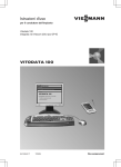
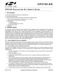
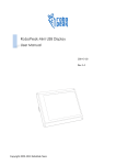
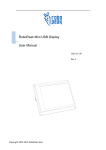
1
RPLIDAR Low Cost 360 degree 2D Laser Scanner (LIDAR) System Development Kit User Manual 2014-2 Rev.1 Copyright 2009-2014 RoboPeak Team http://www.RoboPeak.com Low Cost 360 degree 2D Laser Scanner (LIDAR) System 开发套装使用手册 机密 Contents: 1. OVERVIEW ................................................................................................................................. 2 ITEMS IN DEVELOPMENT KIT ...................................................................................................................... 2 RPLIDAR ............................................................................................................................................... 2 USB ADAPTER ......................................................................................................................................... 3 2. CONNECTION AND USAGE....................................................................................................... 4 CONNECTION .......................................................................................................................................... 4 INSTALL DRIVER FOR THE USB ADAPTER ..................................................................................................... 5 RUN DEMO APPLICATION ......................................................................................................................... 6 TROUBLE SHOOTING................................................................................................................................. 8 3. DEVELOPMENT GUIDE AND SDK INTRODUCTION ................................................................... 9 PIN DEFINITION FOR RPLIDAR ................................................................................................................. 9 PIN DEFINITION FOR USB ADAPTER ......................................................................................................... 10 CONFIGURE RPLIDAR SCAN FREQUENCY................................................................................................. 10 SDK USAGE .......................................................................................................................................... 11 4. OPERATION RECOMMENDATION ........................................................................................... 12 PRE-HEATING FOR BEST PERFORMANCE .................................................................................................... 12 AMBIENT TEMPERATURE .......................................................................................................................... 12 AMBIENT LIGHT ..................................................................................................................................... 12 5. REVISION HISTORY .................................................................................................................. 13 1 / 13 Copyright 2009-2014 RoboPeak http://www.RoboPeak.com 机密 Low Cost 360 degree 2D Laser Scanner (LIDAR) System 开发套装使用手册 1. Overview Thank you for purchasing RPLIDAR development kit. By using this kit, customers can easily evaluating RPLIDAR’s performance. RoboPeak also provides SDK code to help customers integrate RPLIDAR to their system. Items in Development Kit RPLIDAR Development Kit contains: RPLIDAR(PWM motor driver embedded) USB Adapter RPLIDAR communication cable Micro-USB cable USB Adapter RPLIDAR Micro-USB cable RPLIDAR communication cable RPLIDAR 2 / 13 Copyright 2009-2014 RoboPeak http://www.RoboPeak.com 机密 Low Cost 360 degree 2D Laser Scanner (LIDAR) System 开发套装使用手册 RPLIDAR development kit contains standard RPLIDAR unit (A1M1-R1). The RPLIDAR embedded logic IO drivable (3.3V) motor controller which can be used to configure scan frequency by tuning motor speed. Developer also can choose to turn off motor for power saving purpose. RPLIDAR usage and interface definition will be introduced in the coming sections. USB Adapter RPLIDAR development kit contains a USB adapter to provide power supply for RPLIDAR and convert RPLIDAR internal UART serial interface to USB interface. 3 / 13 Copyright 2009-2014 RoboPeak http://www.RoboPeak.com Low Cost 360 degree 2D Laser Scanner (LIDAR) System 开发套装使用手册 机密 2. Connection and Usage Connection RPLIDAR can be easily connect to PC by following bellow steps. 1) Connect RPLIDAR with the USB adapter using provided communication cable. The socket is in the bottom of RPLIDAR. 2) Connect the USB adapter to your PC using the Micro-USB cable After connecting RPLIDAR to your PC through the USB cable, the LED in the bottom of the RPLIDAR will light up and RPLIDAR start scanning. 4 / 13 Copyright 2009-2014 RoboPeak http://www.RoboPeak.com Low Cost 360 degree 2D Laser Scanner (LIDAR) System 开发套装使用手册 Install Driver for the USB Adapter 机密 The USB adapter converts UART to USB using CP2102 chip. You need to install the device driver for the chip. The driver can be found in the provided SDK package or download from Silicon Labs’s official website: http://www.silabs.com/products/interface/usbtouart/Pages/usb-to-uart-bridge.aspx Here’s the installation steps in Windows: After connecting the RPLIDAR with PC, find the driver file “CP210x VCP Windows” and choose correct operating system version accordingly: x86 for 32-bit OS and x64 for 64-bit OS. After Installing the driver according to installation steps, you should see corresponding serial port name in the [Control Panel] -> [Device and Printers]. Please refer to the bellow figure. 5 / 13 Copyright 2009-2014 RoboPeak http://www.RoboPeak.com Low Cost 360 degree 2D Laser Scanner (LIDAR) System 开发套装使用手册 机密 Run Demo Application Frame_grabber is a GUI demo application provided by RoboPeak. You can view the scan result directly in the UI and save the scan result to files for further processing. The source code of this demo application is also provided for reference. This GUI demo can only run under Windows. For Linux and MacOS users, please refer to the other simple demo provided in the SDK. Steps to run the GUI demo application: Please make sure you have connect RPLIDAR to PC using USB adapter and installed the device driver correctly before running the demo application. Starting demo application frame_grabber.exe and choose serial port name identified in the previous step. If the connection is ok, you shall see the UI like this: 6 / 13 Copyright 2009-2014 RoboPeak http://www.RoboPeak.com 机密 Low Cost 360 degree 2D Laser Scanner (LIDAR) System 开发套装使用手册 The firmware/hardware version and serial number of the RPLIDAR will show in the title line of the GUI. The supported commands of RPLIDAR are showed in the tool bar. The descriptions are listed in the bellow table. Button Function Start Scan Stop Scan Save Scan Data Description Scan data will be displayed after scan core starting work Scan core enter power save mode Save current scan data to the local file Restart RPLIDAR Restart scan core to clear internal errors Press the Start Scan button ,the scan data will be displayed in the UI: 7 / 13 Copyright 2009-2014 RoboPeak http://www.RoboPeak.com Low Cost 360 degree 2D Laser Scanner (LIDAR) System 开发套装使用手册 机密 Use the mouse wheel to zoom in and out. Move the cursor to any sample point, the distance and degree value to the RPLIDAR will be showed in the screen with red font. The scan frequency also showed in the UI. Trouble shooting When scan core or laser power works abnormally, scan core will enter protection mode. This state can be retrieved using SDK API. If such scenario happened, sending restart command can let scan core reset. 8 / 13 Copyright 2009-2014 RoboPeak http://www.RoboPeak.com 机密 Low Cost 360 degree 2D Laser Scanner (LIDAR) System 开发套装使用手册 3. Development Guide and SDK Introduction Pin Definition for RPLIDAR The socket in the bottom of RPLIDAR is using 5267-7A specification: 2.5mm spacing 7 pin. Any communication cable has 5264-7 terminal block can be used to connect with RPLIDAR. Please find the detail pin definition in the bellow table: P1 … P7 5267-7A Pin P1 Signal name Type VMOTO Power P2 MOTOCTL Input P3 P4 P5 P6 P7 GND V5.0 TX RX GND Power Power Output Input Power Description Power supply for the RPLIDAR scan motor Enable pin for RPLIDAR scan motor/PWM control signal (active high) GND signal for RPLIDAR scan motor Power supply for RPLIDAR scan core Serial output for RPLIDAR scan core Serial input for RPLIDAR scan core GND signal for RPLIDAR scan core Minimum - Typical 5V Maximum 9V 0V - VMOTO 3.6V 0V 0V - 0V 5V 0V 6V 5V 5V V5.0 External system must provide required VMOTO and V5.0 power to make scan motor and scan core work correctly. In most of scenarios, VMOTO and V5.0 can share the same power supply. MOTOCTL Pin used to control scan motor speed to adjust RPLIDAR’s scan frequency, PWM signal also can be applied. The equivalent circuit showed as bellow: You can also refer to the bellow Reference Design for RPLIDAR development. 9 / 13 Copyright 2009-2014 RoboPeak http://www.RoboPeak.com 机密 Low Cost 360 degree 2D Laser Scanner (LIDAR) System 开发套装使用手册 RPLIDAR VMOTO Power GND (4-9V DC) V5.0 Power (5V DC) GND TX UART RX MOTOCTL PWM Generator MCU/DSP Pin Definition for the USB Adapter The USB adapter is also using 5267-7A specification socket: 2.5mm spacing 7 pin. Please find the detail pin definition in the bellow table: P1 … P7 5267-7A Pin Signal Name Description P1 P2 P3 P4 P5 P6 P7 V5.0 HIGH GND V5.0 RX TX GND Power supply for RPLIDAR scan core, USB 5V input constant 5V high level output GND for RPLIDAR scan motor, USB GND Power supply for RPLIDAR scan core, USB 5V input Input pin for USB serial adapter Output pin for USB serial adapter GND for RPLIDAR scan core, USB GND Configure RPLIDAR Scan Frequency Since USB adapter’s control signal MOTOCTL is fixed to high level, RPLIDAR’s scan motor is always rotating at its highest speed which makes RPLIDAR working on a relative high scan frequency. You can configure RPLIDAR’s scan frequency by controlling motor speed. By connecting MOTOCTL signal to the device has PWM output function such as MCU’s PWM output I/O port, RPLIDAR’s scan frequency can be locked in a proper value by adjust duty ratio of PWM using the scan frequency feedback provided by RPLIDAR core. 10 / 13 Copyright 2009-2014 RoboPeak http://www.RoboPeak.com Low Cost 360 degree 2D Laser Scanner (LIDAR) System 开发套装使用手册 机密 Please refer to RPLIDAR protocol and application note for more information. SDK also contains the sample code. SDK Usage RoboPeak provides RPLIDAR SDK support both Windows and Linux platform. The SDK contains sample code. Please refer to SDK document for more information. 11 / 13 Copyright 2009-2014 RoboPeak http://www.RoboPeak.com Low Cost 360 degree 2D Laser Scanner (LIDAR) System 开发套装使用手册 机密 4. Operation Recommendation Pre-Heating for best performance The scan core will heating when start working. We recommended pre-heating RPLIDAR (Start scan mode, the scan motor is rotating) for more than 2 minutes to get the best measurement accuracy. Ambient Temperature RPLIDAR’s measurement resolution is sensitive to the ambient temperature. Improper use may even damage the sensor. Please avoid using RPLIDAR in extreme high temperature (>40 degree) and too low temperature (<-10 degree). Ambient Light Although RPLIDAR is not sensitive to ambient light, improper use may still lead to errors. In indoor environment, please avoid lighting RPLIDAR with strong light source such as high-power laser. In outdoor environment, please avoid facing RPLIDAR directly into sun light. This may leads to permanent damage to the image sensor of RPLIDAR. The standard version of RPLIDAR may have less measurement range in strong sun light environment. Please contact RoboPeak for any customization options. 12 / 13 Copyright 2009-2014 RoboPeak http://www.RoboPeak.com Low Cost 360 degree 2D Laser Scanner (LIDAR) System 开发套装使用手册 机密 5. Revision History Date 2013-3-5 Content Initial draft 2014-2-11 Refine for final product 13 / 13 Copyright 2009-2014 RoboPeak http://www.RoboPeak.com