1
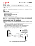
CP2105-EK CP2105 E VALUATION K IT U SER ’ S G UIDE 1. Kit Contents The CP2105 Evaluation Kit contains the following items: CP2105 Evaluation Board CP210x Drivers and Product Information CD-ROM. CD content includes: Virtual COM Port Drivers for Windows®, Linux®, and Mac® USBXpress Driver Development Kit for Windows Documentation: CP2105 Data Sheet CP2105 Evaluation Kit User's Guide Two RS232 Serial Cables USB Cable CP210x 2. Software Setup The included CD-ROM contains the Virtual COM Port Drivers, USBXpress Driver Development Kit and additional documentation. Insert the CD-ROM into a system's CD-ROM drive. If using a Windows PC an installer will automatically launch, allowing you to install the software or read documentation by clicking buttons on the Installation Panel. If the installer does not automatically start when you insert the CD-ROM, run autorun.exe found in the root directory of the CD-ROM. Refer to the ReleaseNotes CP21xx CD.txt file on the CD-ROM for the latest information regarding versions and known problems and restrictions. If a non-Windows PC is used, manually browse to the directory on the CD-ROM that contains the software for your OS. The instructions in this document assume a Windows PC is being used. In the installation application, select the options for your kit. The sections below include more information on the software being installed. 2.1. Virtual COM Port Driver Installation Press the “Install CP21xx Tools” button on the main installation panel to access CP210x Virtual COM Port Drivers for Windows. Virtual COM Port drivers for Linux and Mac operating systems are located on the CD but are not installed automatically. See the following sections for installation instructions on your specific operating system. 2.1.1. Virtual COM Port Driver Installation for Windows The VCP driver installation process for Windows is a two phase process. First, the files needed for the driver installation are “unpacked” to a location on the computer. Next, the unpacked files are used to install the Virtual COM Port driver: 1. Press the “Install CP21xx Tools” button on the main installation panel to access CP210x Virtual COM Port Drivers for Windows. 2. Choose the option for your kit. 3. Selecting the “Install CP210x Drivers” option will run an “unpacker” utility that will install files to the specified path. 4. If the “Launch the CP210x VCP Driver Installer” option was selected during the unpacking phase, the driver installer will take the files that were installed during the unpacking phase and use them for installation. If the “Launch the CP210x VCP Driver Installer” option was not selected, the driver installer can be run by browsing to the location where the files were unpacked and running CP210xVCPInstaller.exe. The default unpacking location is C:\SiLabs\MCU\CP210x\Windows. 5. To complete the installation process, connect a USB cable between the host computer and the CP210x Evaluation Board. Windows will automatically finish the driver installation. Information windows will pop up from the taskbar to show the installation progress. 6. If needed, the driver files can be uninstalled by selecting “Silicon Laboratories CP210x USB to UART Rev. 0.4 11/10 Copyright © 2010 by Silicon Laboratories CP2105-EK CP2105-EK Bridge (Driver Removal)” option in the “Add or Remove Programs” window. 2.1.2. Virtual COM Port Driver Installation for Macintosh The Mac drivers are not automatically installed, but can be found on the CD-ROM in the CP210x\Mac directory. This directory contains Virtual COM Port drivers for OS9 and OSX. To install the Mac OSX virtual COM port driver, perform the following steps: 1. Extract the Mac_OSX_VCP_Driver.zip file. 2. Next, run the extracted file, SLAB_USBtoUART Installer. 3. To uninstall the driver, run the extracted file, SLAB_USBtoUART Uninstaller. 2.1.3. Virtual COM Port Driver Installation for Linux The Linux drivers are not automatically installed but can be found on the CD-ROM in the CP210x\Linux directory. This directory contains Virtual COM Port drivers for Linux 2.6 and Linux RedHat 2.4. To install the drivers, follow the installation instructions located in the appropriate ReleaseNotes.txt file. 2.2. USBXpress Driver Development Kit The Silicon Laboratories USBXpress® Development Kit provides a complete host software solution for interfacing to CP210x devices. No USB protocol or host device driver expertise is required. Instead, a simple, high-level Application Program Interface (API) for the host software is used to provide complete USB connectivity. The USBXpress Development Kit includes Windows device drivers, Windows device driver installer, and host interface function library (host API) provided in the form of a Windows Dynamic Link Library (DLL). See “AN169: USBXpress Programmer's Guide” for detailed information on customizing the USBXpress drivers. 2.2.1. USBXpress Installation for Windows Press the “Install CP21xx Tools” button on the main installation panel to access the USBXpress Development Kit for Windows. Choose the option for your kit. Ensure that the “Install USBXpress” option is selected. The default installation directory is C:\SiLabs\MCU\USBXpress. 2.2.2. USBXpress Installation for Windows CE The USBXpress Development Kit for Windows CE can be found on the CD-ROM in the USBXpress\Windows_CE directory. This directory contains a USBXpress kit for Window CE 4.2, 5.0 and 6.0. Follow the installation instructions located in the appropriate ReleaseNotes.txt file. 2 Rev. 0.4 CP2105-EK 3. CP2105 Hardware Interface Connect the CP2105 evaluation board to a PC as shown in Figure 1. 1. Connect one end of the USB cable to a USB Port on the PC. 2. Connect the other end of the USB cable to the USB connector on the CP2105 evaluation board. 3. Connect one end of the RS232 serial cable to one of the DB-9 connectors on the CP2105 evaluation board. 4. Connect the other end of the RS232 serial cable to the target serial device. RS232 USB Port RS232 USB Cable CP2105 Eval Board RS232 USB PC Serial Device RS232 5. Repeat Steps 3 and 4 using a second RS232 serial cable and the unused DB-9 connector on the CP2105 evaluation board. Serial Device Figure 1. Hardware Setup 4. CP2105 Software Interface If the Virtual COM Port drivers are used, the CP2105 will appear as two COM ports in the Device Manager, as shown in Figure 2. The CP2105 will always use the lowest available COM port for operation. For instance, if COM Ports 1 through 3 are in use by other peripherals and applications, the CP2105 will use COM 4 and COM 5. The CP2105 functions identically to a COM port from the reference point of both the host application and the serial device, and it can support serial device control requests defined in the Microsoft Win32® Communications API. If the USBXpress drivers are used, the CP2105 will appear as two USB USBXpress devices as shown in Figure 2. Figure 2. CP210x in Device Manager Rev. 0.4 3 CP2105-EK 5. Target Board The CP2105 Evaluation Kit includes an evaluation board with a CP2105 device preinstalled for evaluation and preliminary software development. Numerous input/output (I/O) connections are provided to facilitate prototyping using the evaluation board. Refer to Figure 3 for the locations of the various I/O connectors. P1 P2 P3 J1 J2, J3 J4 J6 J7, J8 DSS–DS4 DS5 USB connector for USB interface DB9 connector for Standard RS232 interface DB9 connector for Enhanced RS232 interface Enhanced UART signal access connector GPIO access connector Power connector Standard UART signal access connector SUSPEND LED source connector Green GPIO LEDs Red SUSPEND indicator LED J6 CP2105-EK P3 J2 DS0 DS1 RS232 Transceiver Pin 1 Enhanced Pin 2 P1 J8 ______ CP2105 J7 SUSPEND LED DS5 P2 RS232 Transceiver Pin 1 J3 Standard Pin 2 J4 J1 DS2 DS3 DS4 Figure 3. CP2105 Evaluation Board with Default Shorting Blocks Installed 5.1. LED Headers (J2, J3) Connectors J2 and J3 are provided to allow access to the GPIO pins on the CP2105 when in GPIO mode. Place shorting blocks on J2 and J3 to connect the GPIO pins to the five green LEDs DS0–DS4. These LEDs can be used to indicate active communications through the CP2105. Table 1 shows the LED corresponding to each header position. When using the CP2105 in Modem mode, the shorting blocks on J2 and J3 should be removed. Table 1. J2 and J3 LED Locations 4 LED Pins DS0 J2[1:2] DS1 J2[3:4] DS2 J3[1:2] DS3 J3[3:4] DS4 J3[5:6] Rev. 0.4 CP2105-EK 5.2. Universal Serial Bus (USB) Interface (P1) A Universal Serial Bus (USB) connector (P1) is provided to facilitate connections to the USB interface on the CP2105. See Table 2 for the USB pin definitions. Table 2. USB Connector Pin Descriptions Pin # Description 1 2 3 4 VBUS DD+ GND (Ground) 5.3. UART Signals (P2, P3, J1, J6) Two RS232 transceiver circuits and DB-9 connectors (P2, P3) are provided on the evaluation board to connect the CP2105 virtual serial ports to external serial devices. See Table 3 for the RS232 P2 and P3 pin descriptions. The J2 and J6 connectors are provided to facilitate direct access to the CP2105’s UART signals. Shorting blocks on J1 are required to connect the Standard UART signals to P2, and the shorting blocks on J6 are required to connect the Enhanced UART signals to P3. See Table 4 for J1 and J6 pin descriptions. Table 3. RS232 Pin Descriptions Pin Signal 1 2 3 4 5 6 7 8 9 DCD RXD TXD DTR GND DSR RTS CTS RI CP2105 Direction Input Input Output Output Input Output Input Input Description Data Carrier Detect Receive Data Transmit Data Data Terminal Ready Ground Data Set Ready Request to Send Clear to Send Ring Indicator Table 4. J1, J6 Pin Descriptions Pins Signal CP2105 Direction Description 1-2 3-4 5-6 7-8 9-10 11-12 13-14 15-16 TXD RXD DTR RI DCD DSR CTS RTS Output Input Output Input Input Input Input Output Transmit Data Receive Data Data Terminal Ready Ring Indicator Data Carrier Detect Data Set Ready Clear to Send Request to Send Rev. 0.4 5 CP2105-EK 5.4. Power Connector (J4) This header (J4) is included on the evaluation board to provide several power options. The following describes the functions of the pins. Pins 1–2 connect CP2105 VIO input (Pin 5) to CP2105 VDD (Pin 6). Remove the shorting block to power VIO from an external source. Pins 3–4 connect the main +3 V net to the CP2105 VDD (Pin 6). The main +3 V net powers the other components (five green LEDs and RS-232 Sipex Part) on the board. 5.5. SUSPEND LED Source Selector(J7, J8) These headers (J7, J8) are included on the evaluation board to provide several options for the SUSPEND LED source. The following describes the function of each pin: J7[1:2] connects CP2105 Standard UART SUSPEND output (Pin 1) to the SUSPEND LED. J7[2:3] connects CP2105 Enhanced UART SUSPEND output (Pin 17) to the SUSPEND LED. J7[2]:J8[1] connects the main +3 V net to the SUSPEND LED. This will cause the SUSPEND LED to act as a power LED. 6 Rev. 0.4 Figure 4. CP2105 Evaluation Board Schematic CP2105-EK 6. Schematic Rev. 0.4 7 CP2105-EK DOCUMENT CHANGE LIST Revision 0.1 to Revision 0.2 Updated Windows installation instructions for VCP drivers. Updated Windows installation instructions for USBXpress drivers. Revision 0.2 to Revision 0.3 Updated Figure 3 with shorting blocks installed. Revision 0.3 to Revision 0.4 8 Updated "2. Software Setup" on page 1. Rev. 0.4 CP2105-EK NOTES: Rev. 0.4 9 CP2105-EK CONTACT INFORMATION Silicon Laboratories Inc. 400 West Cesar Chavez Austin, TX 78701 Tel: 1+(512) 416-8500 Fax: 1+(512) 416-9669 Toll Free: 1+(877) 444-3032 Please visit the Silicon Labs Technical Support web page: https://www.silabs.com/support/pages/contacttechnicalsupport.aspx and register to submit a technical support request. The information in this document is believed to be accurate in all respects at the time of publication but is subject to change without notice. Silicon Laboratories assumes no responsibility for errors and omissions, and disclaims responsibility for any consequences resulting from the use of information included herein. Additionally, Silicon Laboratories assumes no responsibility for the functioning of undescribed features or parameters. Silicon Laboratories reserves the right to make changes without further notice. Silicon Laboratories makes no warranty, representation or guarantee regarding the suitability of its products for any particular purpose, nor does Silicon Laboratories assume any liability arising out of the application or use of any product or circuit, and specifically disclaims any and all liability, including without limitation consequential or incidental damages. Silicon Laboratories products are not designed, intended, or authorized for use in applications intended to support or sustain life, or for any other application in which the failure of the Silicon Laboratories product could create a situation where personal injury or death may occur. Should Buyer purchase or use Silicon Laboratories products for any such unintended or unauthorized application, Buyer shall indemnify and hold Silicon Laboratories harmless against all claims and damages. Silicon Laboratories, Silicon Labs, and USBXpress are trademarks of Silicon Laboratories Inc. Other products or brandnames mentioned herein are trademarks or registered trademarks of their respective holders. 10 Rev. 0.4