1
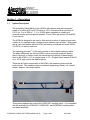
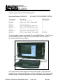
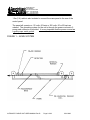
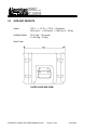
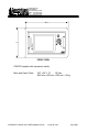
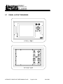
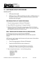
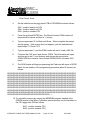
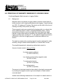
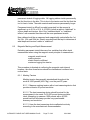
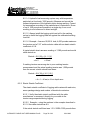
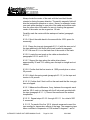
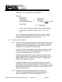
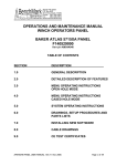
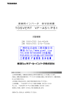
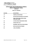
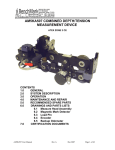
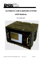
36220 FM 1093 P. O. BOX 850 Simonton,Texas 77476 Phone: 281.342.6415 Fax: 281.342.4848 benchmarkwireline.com AUTOMATIC CABLE MARKING SYSTEM USER MANUAL P/N ACMU6A01 AUTOMATIC CABLE UNIT USER MANUAL Rev.B Page 1 of 83 JUN-2009 36220 FM 1093 P. O. BOX 850 Simonton,Texas 77476 Phone: 281.342.6415 Fax: 281.342.4848 benchmarkwireline.com Section I Description 1.1 1.2 1.3 1.4 Section 2 Installation 2.1 2.2 2.3 Section 3 System Description General Operation Accuracy Calibration Measuring Arm Control Panel Preliminary Test Operation 3.1 3.2 3.3 3.4 3.5 3.6 3.7 Software Instructions – Main Screen Software Instructions – Menu Software Instructions – Mark Reset Marking the Cable Variations of Marking General Comments on Markings Metric System Section 4 Troubleshooting Section 5 Features and Specifications 5.1. 5.2 5.3 5.4 5.5 5.6 5.7 Size and Weight specifications Wiring Diagram Checking / Replacing Fuses Checking Minor Marker / Detector Polarity Reversing Magnetic Mark Polarity Recommended Spare Parts Panel Layout Diagram Section 6 Electrical Diagrams, Schematics, Parts Lists Section 7 New Software Installation Section 8 Principals of Magnetic Marking AUTOMATIC CABLE UNIT USER MANUAL Rev.B Page 2 of 83 JUN-2009 36220 FM 1093 P. O. BOX 850 Simonton,Texas 77476 Phone: 281.342.6415 Fax: 281.342.4848 benchmarkwireline.com Section 1 – Description 1.1 System Description The Automatic Cable Marking Unit (ACMU) will measure and place magnetic marks on a cable at 25 meter, 50 meter or 100 ft. intervals with an accuracy of 0.01% (or .3 m in 3000 m, - 1 ft. in 10,000) when operated on a cable at a constant tension and line speeds between 15 and 185 m per minute (50 and 600 ft. per minute). The ACMU is designed to be used in field service locations to measure and mark a cable as it is spooled under constant tension between two winches. With proper set-up, two men familiar with the ACMU can easily re-calibrate and mark 4500 m (15,000 ft.) of cable in one hour. The operating principal (1) of this unit is similar to that of hand marking a cable. The basic differences are that the ACMU uses a very sharp magnetic mark in place of a pencil or chalk to mark the interval and the interval (or base length) used in the ACMU is 1.67 m (metric base) or 5 ft. (English base) Instead of the 50 m or 100 ft. tape used in the hand marking. There are two basic components in the ACMU; the measuring frame and the control panel. The measuring frame contains a degaussing (erase) coil, interval marker, detector, and major marker. This system replaces the current Kerr ACMU1A01 marking panel. It is compatible with the existing Kerr ACMU2A01, ACMU3A01, and ACMU4A01 marking arms and frame assembly. AUTOMATIC CABLE UNIT USER MANUAL Rev.B Page 3 of 83 JUN-2009 36220 FM 1093 P. O. BOX 850 Simonton,Texas 77476 Phone: 281.342.6415 Fax: 281.342.4848 benchmarkwireline.com A typical system consists of the following items. Parent Item Number: ACMU6A10 KIT ACMU TOUCH SCREEN SYSTEM Component --------------- Description ------------------------------ Qty Required ---------------- ACMU6A01 ACMU6A02 ACMU2A11 ACMU3A31 ACMU4A31 ACMU1A11-30 AMS6A001 ACMU1A11-05 ACMU6P13 AM1KA110 PANEL ASSY ACMU TOUCH SCREEN PANEL ASSY ERASE TRANSFORMER ACMU FRAME ASSY ENGLISH MEASUREMENT BASE ASSY METRIC MEASUREMENT BASE ASSY CABLE ASSY ACMU UMBILICAL 30FT HAND MARK LOCATR (GAUSS METER) CABLE ASSY ACMU UMBILICAL 5FT LOAD CELL 13,000 LB 2mV/V LINK DEVICE CABLE MSRMT 2FT TANGENT 1 1 1 1 1 1 1 1 OPTIONAL OPTIONAL The control panel contains an industrial PC running MS-Windows. The PC input is accomplished by either using the touch screen placed over the display or through a keyboard that is provided. A PC scope card is used to display the minor mark signals. This scope card replaces the conventional oscilloscope used in the old panels. The control panel provides signal to threshold adjustment and both visual and audible indication of AUTOMATIC CABLE UNIT USER MANUAL Rev.B Page 4 of 83 JUN-2009 36220 FM 1093 P. O. BOX 850 Simonton,Texas 77476 Phone: 281.342.6415 Fax: 281.342.4848 benchmarkwireline.com interval marking and the major magnetic mark every 25 or 50 m with metric base or 100 ft. with English base. The panel includes encoder and tension inputs to allow the system to display, record and print depth, tension, and mark data. An intercom system is also included. The intercom provides a means to connect a remote speaker which can be used for voice communication. A connection to an internal relay is provided to allow an external high volume alarm to be used so major marks can be heard in a noisy environment. The system is packaged inside a Hardigg ProRack double lid case. The Erase transformer and Variac are removed from the control panel and packaged in a separate enclosure. This allows the de-gausser to be operated independently from the control panel. It can also be connected through the panel so marks can be erased while the cable is being marked. The ACMU comes with a 9 m (30 ft.) umbilical cable and is wired “pin to pin”, allowing either end of the umbilical cable to be attached to the control cable. A AUTOMATIC CABLE UNIT USER MANUAL Rev.B Page 5 of 83 JUN-2009 36220 FM 1093 P. O. BOX 850 Simonton,Texas 77476 Phone: 281.342.6415 Fax: 281.342.4848 benchmarkwireline.com 1.5m (5 ft.) cable is also included to connect the erase panel to the rear of the control panel. The panel will operate on 115 volts, 60 hertz or 220 volts, 50 or 60 hertz as ordered. The grounding system for the unit is through the power cord and a 3prong male connector is provided. It is very important that the power source has a good proper earth ground. FIGURE 1 – ACMU SYSTEM AUTOMATIC CABLE UNIT USER MANUAL Rev.B Page 6 of 83 JUN-2009 36220 FM 1093 P. O. BOX 850 Simonton,Texas 77476 Phone: 281.342.6415 Fax: 281.342.4848 benchmarkwireline.com 1.2 General Operation The spooling equipment must be set-up to maintain a constant tension over the desired line speed range. This reference tension is usually 450 kg (1000 pounds). With this prerequisite, the system operates as follows: 1.3 1. With the cable stopped, the initial reference mark and the first major mark are applied to the cable. The momentary switch on the control panel also resets the counter. 2. As the cable enters the measuring frame, the degaussing coil magnetically cleans it. 3. With the cable in motion, the reference mark moves the base length and activates the detector. The length of the English base is 5 ft. and the length of the metric base is 1.6667 m. 4. The signal from the detector is displayed on the panel, crosses a displayed threshold line, begins the counter and triggers the reference marker, placing a new reference mark on the cable 1.6667 m (Metric base) or 5 ft. (English base) behind the previous reference mark. 5. This process continues as long as the cable is in motion. At the count of twenty (20), a major magnetic mark is applied 100 ft. behind the previous one and the counter is reset. For 25 m marks, a count of fifteen (15) is used. For 50 m marks, thirty (30) minor marks are used. Accuracy The accuracy of the ACMU system is .01% or .3 m in 3000 m (1 ft in 10,000 ft). This, of course, assumes that the cable under measurement does not change length during the marking operation. Proper set-up of the cable spooling arrangement cannot be over emphasized. Accurate measurement and marking demands a constant tension to eliminate changes in cable length due to the cables’ inherent stretch characteristics. Typical 7 conductor logging cables have an elastic stretch coefficient of .25 -.27 m / 300 m / 450 kg (0.8-0.9 ft. / 1000 ft. / 1000 pounds). In addition, new cables can have an in-elastic (permanent) stretch of up to 0.2% or 6 m in 3000 m (20 ft. in 10,000 ft.) before they are “seasoned”. Using the elastic stretch characteristics only, it is easy to see that a 225 kg (500 pound) variation in tension during marking could result in a possible error of 1.2- AUTOMATIC CABLE UNIT USER MANUAL Rev.B Page 7 of 83 JUN-2009 36220 FM 1093 P. O. BOX 850 Simonton,Texas 77476 Phone: 281.342.6415 Fax: 281.342.4848 benchmarkwireline.com 1.3 m in 3000 m (4 - 4.5 feet in 10,000). A good set-up should hold the reference tension (usually 450 kg or 1000 pounds) constant within + or – 2 ½%. 1.4 Calibration The base (reference) distance is calibrated to a standard traceable to the bureau of standards. The base frame is chosen to match the thermal coefficient of expansion of most logging cables at 450 kg (1000 pounds) tension. In order to maintain the highest degree of accuracy possible with the ACMU, authorized personnel only will perform field calibration. An error of only .4 mm in calibration of the 1.67 m base length with result in an error of almost 1 m in 3000m. An error of 1/64’’ in calibration of the 5 ft. base length will result in an error of almost 3 ft. in 10,000. Section 2 – Installation 2.1 Measuring Arm The measuring arm consists of two basic components: the frame with support rollers and the top measurement base which rides upon the cable. This system does not enclose the cable and can be installed from the side. Each end of the frame will accept a universal joint retaining arm system for versatility of installation. Care must be taken to locate the measuring arm in the cable path where bouncing and erratic cable motion is at a minimum. Keeping in mind that the cable must move through the ACMU from the degaussing coil to the major mark end, the sequence of installation is: 1. Set the frame onto the cable, making sure that the cable rides in the three grooved wheels. 2. Position the hinged measurement base on the cable, ensuring that the cable rides smoothly in the three grooves of the internal marker, detector, and major marker. AUTOMATIC CABLE UNIT USER MANUAL Rev.B Page 8 of 83 JUN-2009 36220 FM 1093 P. O. BOX 850 Simonton,Texas 77476 Phone: 281.342.6415 Fax: 281.342.4848 benchmarkwireline.com FIGURE 2 – COIL INSTALLATION AUTOMATIC CABLE UNIT USER MANUAL Rev.B Page 9 of 83 JUN-2009 36220 FM 1093 P. O. BOX 850 Simonton,Texas 77476 Phone: 281.342.6415 Fax: 281.342.4848 benchmarkwireline.com FIGURE 3 – TYPICAL INSTALLATION 3. Move the three retaining wheels into position immediately below the three grooved wheels and make sure that the spring loaded locks are in place. 4. Move the frame along the cable to a convenient location and attach the retaining arm with universal joint system onto (as preferred) the: A. Breaking Capstan B. Truck Bumper C. Garage Winch 5. The erase coil is then spiraled around the cable and firmly attached with “wing nuts” to the two erase terminals. AUTOMATIC CABLE UNIT USER MANUAL Rev.B Page 10 of 83 JUN-2009 36220 FM 1093 P. O. BOX 850 Simonton,Texas 77476 Phone: 281.342.6415 Fax: 281.342.4848 benchmarkwireline.com 2.2 6. Remove the dust cap and attach one end of the umbilical cable to the measurement frame via the fourteen contact connector. Preliminary Test 1. Plug the unit into a well-grounded power source. 2. Turn the erase potentiometer to 0. 3. Turn on the operating switch and allow 30 seconds for the unit to warm up. 4. When the power switch is turned on, an audible “beep” occurs for 1 to 3 seconds. 5. Two horizontal lines should appear on the CRT. 6. Adjust the intensity and focus controls for proper display on the CRT. 7. Turn the erase potentiometer control up to 50 on the dial and note that the current indicating light becomes brighter as it approaches 50. 8. Push the momentary reset and manual mark switch and note that the counting indicator lights return to “0”. The red “0” light should remain on. Both meters should indicate a momentary voltage reduction indicating continuity to the markers. 9. Turn the erase potentiometer to 0 and turn off the unit. 10. The unit is ready for marking cable. 11. During this test, a major magnetic mark has been placed on the cable (step no. 8). If the measurement arm has not been placed at the desired starting point, this mark must be removed by passing it through the erase coil. AUTOMATIC CABLE UNIT USER MANUAL Rev.B Page 11 of 83 JUN-2009 36220 FM 1093 P. O. BOX 850 Simonton,Texas 77476 Phone: 281.342.6415 Fax: 281.342.4848 benchmarkwireline.com Section 3 – Operation 3.1 Panel Software – Main Screen When the system first boots up, the main screen will appear. Most of the commands are accessed through the buttons across the bottom of the screen. EXIT: Will close this program THRESHOLD: This slider will move the threshold trace which is visible on this main screen. The proper setting of this threshold level is critical to the marking job. AUTOMATIC CABLE UNIT USER MANUAL Rev.B Page 12 of 83 JUN-2009 36220 FM 1093 P. O. BOX 850 Simonton,Texas 77476 Phone: 281.342.6415 Fax: 281.342.4848 benchmarkwireline.com AUTOMATIC CABLE UNIT USER MANUAL Rev.B Page 13 of 83 JUN-2009 36220 FM 1093 P. O. BOX 850 Simonton,Texas 77476 Phone: 281.342.6415 Fax: 281.342.4848 benchmarkwireline.com Shown above is the main menu with the Double Mark error condition. AUTOMATIC CABLE UNIT USER MANUAL Rev.B Page 14 of 83 JUN-2009 36220 FM 1093 P. O. BOX 850 Simonton,Texas 77476 Phone: 281.342.6415 Fax: 281.342.4848 benchmarkwireline.com Shown above is the main screen with both Tension 1 and 2 enabled. The ALARM SILENCE option on the main screen allows for a quick way to silence both alarms. The alarms will sound again when a new alarm condition occurs. AUTOMATIC CABLE UNIT USER MANUAL Rev.B Page 15 of 83 JUN-2009 36220 FM 1093 P. O. BOX 850 Simonton,Texas 77476 Phone: 281.342.6415 Fax: 281.342.4848 benchmarkwireline.com 3.2 MAIN MENU Following are the functional descriptions of each of the buttons. 3.2.1 ENCODER PPR The Set Encoder PPR entry screen will appear. The range is 1-2000 AUTOMATIC CABLE UNIT USER MANUAL Rev.B Page 16 of 83 JUN-2009 36220 FM 1093 P. O. BOX 850 Simonton,Texas 77476 Phone: 281.342.6415 Fax: 281.342.4848 benchmarkwireline.com The screen allows you to set the encoder pulses per revolution setting. This number should be printed on the encoder label. Note: The pulses per foot/meter are not set by this screen, only the encoder input. Pulses per foot/meter are calculated from encoder PPR and Wheel Size. This option is meaningful only if utilizing an encoder for depth measurement. Default is 1200 PPR 3.2.2 ENCODER DIRECTION This screen allows you to change the direction of the encoder. If the depth is changing in the opposite direction to which the line is moving, this option can be used to correct it. On a dual wheel measuring device with two encoders, the encoder on one of the wheels will turn in the opposite direction from the other. If you change encoders, this feature can be used to change the encoder direction. Note: This option is only meaningful if an encoder is utilized for depth measurement. AUTOMATIC CABLE UNIT USER MANUAL Rev.B Page 17 of 83 JUN-2009 36220 FM 1093 P. O. BOX 850 Simonton,Texas 77476 Phone: 281.342.6415 Fax: 281.342.4848 benchmarkwireline.com 3.2.3 ENCODER STATUS This option is only meaningful if an encoder is connected to the panel. The encoder resolution must be specified correctly and the wheel size and, optionally shim, must be known accurately to ensure proper depth operation. 3.2.4 HELP AUTOMATIC CABLE UNIT USER MANUAL Rev.B Page 18 of 83 JUN-2009 36220 FM 1093 P. O. BOX 850 Simonton,Texas 77476 Phone: 281.342.6415 Fax: 281.342.4848 benchmarkwireline.com The HELP button will display the three options displayed above. 3.2.4.1 MANUAL The HELP button will bring up this manual in pdf format. You can scroll up or down to find the information you need. Note: The manual .pdf file must reside on the panel’s internal C: drive in the root directory to be found by this program. 3.2.4.2 ABOUT The ABOUT button displays the software revisions. Note: If the acquisition program rev shows 1.00 as shown above – this is an error condition – re-start the panel and ensure that the acquisition program rev is higher than 1.00. AUTOMATIC CABLE UNIT USER MANUAL Rev.B Page 19 of 83 JUN-2009 36220 FM 1093 P. O. BOX 850 Simonton,Texas 77476 Phone: 281.342.6415 Fax: 281.342.4848 benchmarkwireline.com 3.2.5 WHEEL SIZE The Set Wheel Range entry screen will appear. The range is .3-10.0 Ft. This setting allows you to change the size of the depth measuring wheel that is used to measure depth. To use a different measuring head from the Benchmark head, this setting will need to be changed to match the wheel size of the new head. Default value is 2.0. Note: This option is meaningful when utilizing an encoder for depth measurement. Wheel size and shim must be very accurate for the encoder depth to be accurate. AUTOMATIC CABLE UNIT USER MANUAL Rev.B Page 20 of 83 JUN-2009 36220 FM 1093 P. O. BOX 850 Simonton,Texas 77476 Phone: 281.342.6415 Fax: 281.342.4848 benchmarkwireline.com 3.2.6 ENGLISH/METRIC UNITS This menu allows you to select the display units for either depth or tension. Default is feet and lbs. Note: It is recommended to change these only before a job and not during the middle of a job. AUTOMATIC CABLE UNIT USER MANUAL Rev.B Page 21 of 83 JUN-2009 36220 FM 1093 P. O. BOX 850 Simonton,Texas 77476 Phone: 281.342.6415 Fax: 281.342.4848 benchmarkwireline.com 3.2.7 MARK TABLE Displays the major mark depths since the last time reset marks was performed or the program was invoked. AUTOMATIC CABLE UNIT USER MANUAL Rev.B Page 22 of 83 JUN-2009 36220 FM 1093 P. O. BOX 850 Simonton,Texas 77476 Phone: 281.342.6415 Fax: 281.342.4848 benchmarkwireline.com 3.2.8 MARK SPACING The Mark Spacing entry screen will appear. The valid inputs include 10M, 20M, 25M, 50M, 50F, and 100F. Note: To utilize 10M, 20M, 25M, or 50M, the panel must be set to Metric mode. To utilize 50 FT or 100 Ft the panel must to set to English mode. 3.2.9 DEPTH AUTOMATIC CABLE UNIT USER MANUAL Rev.B Page 23 of 83 JUN-2009 36220 FM 1093 P. O. BOX 850 Simonton,Texas 77476 Phone: 281.342.6415 Fax: 281.342.4848 benchmarkwireline.com 3.2.9.1 SET DEPTH The Set Depth entry screen will appear. The range is 9999.9 → 99999.8 feet or -3048 → 30480 meters. Note: This option is meaningful if, for example, this panel was started in the middle of a job where a known length of line has already been spooled. AUTOMATIC CABLE UNIT USER MANUAL Rev.B Page 24 of 83 JUN-2009 36220 FM 1093 P. O. BOX 850 Simonton,Texas 77476 Phone: 281.342.6415 Fax: 281.342.4848 benchmarkwireline.com 3.2.9.2 SHIM The Set Depth Shim entry screen will appear. The range is 10.00 → 10.00 ft/Kft or -10 → 10 Mt/KMT. Adds or subtracts depth continually. If 1 is entered then 1 foot or 1 meter will be added every 1000 feet or 1000 meters. If -.2 is entered then .2 feet or .2 meters will be subtracted every 1000 feet or 1000 meters. Default is 0.0 Note: This option is meaningful only if an encoder is utilized for depth and if the option is enabled. An example for its use is if the encoder wheel is known to be over/under sized. AUTOMATIC CABLE UNIT USER MANUAL Rev.B Page 25 of 83 JUN-2009 36220 FM 1093 P. O. BOX 850 Simonton,Texas 77476 Phone: 281.342.6415 Fax: 281.342.4848 benchmarkwireline.com 3.2.10 TENSION The Tension Setup Menu will appear. Following are functional descriptions of each button: Tension 1 / 2 Calibrate refer to section 3.2.10.1 Tension 1 / 2 Scale refer to section 3.2.10.2 Tension 1 Volts Fullscale refer to section 3.2.10.3 Tension 2 Sensitivity refer to section 3.2.10.4 Weight Fullscale refer to section 3.2.10.5 Tension 1 Status refer to section 3.2.10.6 Tension 2 Status refer to section 3.2.10.7 AUTOMATIC CABLE UNIT USER MANUAL Rev.B Page 26 of 83 JUN-2009 36220 FM 1093 P. O. BOX 850 Simonton,Texas 77476 Phone: 281.342.6415 Fax: 281.342.4848 benchmarkwireline.com 3.2.10.1 TENSION 1 / 2 CALIBRATE Tension zero will zero out the tension reading to establish a baseline reading. Note: The other buttons in this menu are not available. AUTOMATIC CABLE UNIT USER MANUAL Rev.B Page 27 of 83 JUN-2009 36220 FM 1093 P. O. BOX 850 Simonton,Texas 77476 Phone: 281.342.6415 Fax: 281.342.4848 benchmarkwireline.com 3.2.10.2 TENSION 1 / 2 SCALE This option is only used to rescale the visual bar graph. Its setting does not affect the actual tension reading. AUTOMATIC CABLE UNIT USER MANUAL Rev.B Page 28 of 83 JUN-2009 36220 FM 1093 P. O. BOX 850 Simonton,Texas 77476 Phone: 281.342.6415 Fax: 281.342.4848 benchmarkwireline.com 3.2.10.3 TENSION 1 VOLTS FULLSCALE The Set Volts Fullscale entry screen will appear. This option scales the load device fullscale output. Note: This option is for Tension 1 device only. AUTOMATIC CABLE UNIT USER MANUAL Rev.B Page 29 of 83 JUN-2009 36220 FM 1093 P. O. BOX 850 Simonton,Texas 77476 Phone: 281.342.6415 Fax: 281.342.4848 benchmarkwireline.com 3.2.10.4 TENSION 2 SENSITIVITY The Set Sensitivity in mv/v entry screen will appear. Note: This option is for load device 2 only. For accurate tension measurements, this setting should match the load device manufacturer’s specification for sensitivity. 3.2.10.5 WEIGHT FULLSCALE 1 / 2 The Set Fullscale Tension entry screen will appear. AUTOMATIC CABLE UNIT USER MANUAL Rev.B Page 30 of 83 JUN-2009 36220 FM 1093 P. O. BOX 850 Simonton,Texas 77476 Phone: 281.342.6415 Fax: 281.342.4848 benchmarkwireline.com This should match the load device manufacturer’s specification for fullscale tension. AUTOMATIC CABLE UNIT USER MANUAL Rev.B Page 31 of 83 JUN-2009 36220 FM 1093 P. O. BOX 850 Simonton,Texas 77476 Phone: 281.342.6415 Fax: 281.342.4848 benchmarkwireline.com 3.2.10.6 TENSION 1 STATUS This option informs the panel software which type of load device is being utilized. Note: The external cabling must also conform to the type of device utilized and also note the correct jumper position inside the panel. Aslo note: If there is no tension device, it is recommended to set this option to: Disabled. Default: Disabled. AUTOMATIC CABLE UNIT USER MANUAL Rev.B Page 32 of 83 JUN-2009 36220 FM 1093 P. O. BOX 850 Simonton,Texas 77476 Phone: 281.342.6415 Fax: 281.342.4848 benchmarkwireline.com 3.2.10.7 TENSION 2 STATUS Default: Disabled Note: If there is no tension device, it is recommended to disable this option. AUTOMATIC CABLE UNIT USER MANUAL Rev.B Page 33 of 83 JUN-2009 36220 FM 1093 P. O. BOX 850 Simonton,Texas 77476 Phone: 281.342.6415 Fax: 281.342.4848 benchmarkwireline.com 3.2.11 ALARMS Tension Alarm: refer to 3.2.11.1 Surface Alarm: refer to 3.2.11.2 Max Depth Alarm: refer to 3.2.11.3 Test Minor Mark Alarm: refer to 3.2.11.4 Minor Mark Alarm Off: refer to 3.2.11.5 Minor Mark Alarm Volume: refer to 3.2.11.6 Test Major Mark Alarm: refer to 3.2.11.7 Major Mark Alarm Off: refer to 3.2.11.8 Major Mark Alarm Volume: refer to 3.2.11.9 Test Relay: refer to 3.2.11.10 Open Relay: refer to 3.2.11.11 AUTOMATIC CABLE UNIT USER MANUAL Rev.B Page 34 of 83 JUN-2009 36220 FM 1093 P. O. BOX 850 Simonton,Texas 77476 Phone: 281.342.6415 Fax: 281.342.4848 benchmarkwireline.com 3.2.11.1 TENSION ALARM The Set Tension Alarm entry screen will appear. The range is 0.1 → 19999 lbs or -1 → 9090 kgs. Note: This alarm pertains to tension 1 device only. AUTOMATIC CABLE UNIT USER MANUAL Rev.B Page 35 of 83 JUN-2009 36220 FM 1093 P. O. BOX 850 Simonton,Texas 77476 Phone: 281.342.6415 Fax: 281.342.4848 benchmarkwireline.com 3.2.11.2 SURFACE ALARM The Set Surface Alarm entry screen will appear. The range is 0 to 999 ft or 0 to 305 meters. When this depth value is reached, the alarm will sound warning the operator that you are approaching the surface. Default value is 100 feet or 305 meters. AUTOMATIC CABLE UNIT USER MANUAL Rev.B Page 36 of 83 JUN-2009 36220 FM 1093 P. O. BOX 850 Simonton,Texas 77476 Phone: 281.342.6415 Fax: 281.342.4848 benchmarkwireline.com 3.2.11.3 MAX DEPTH ALARM The Set Max Depth Alarm entry screen will appear. The range is from the surface alarm setting to 30,000 feet or 9144 meters. This option allows you to enter in the maximum depth desired. If the line goes below that depth then an alarm will sound. Default: 30,000 ft or 9144 meters. AUTOMATIC CABLE UNIT USER MANUAL Rev.B Page 37 of 83 JUN-2009 36220 FM 1093 P. O. BOX 850 Simonton,Texas 77476 Phone: 281.342.6415 Fax: 281.342.4848 benchmarkwireline.com 3.2.11.4 TEST MINOR MARK ALARM This button will sound the Minor Mark alarm. This can be used to verify the alarm is working and to determine if the volume is adequate. AUTOMATIC CABLE UNIT USER MANUAL Rev.B Page 38 of 83 JUN-2009 36220 FM 1093 P. O. BOX 850 Simonton,Texas 77476 Phone: 281.342.6415 Fax: 281.342.4848 benchmarkwireline.com 3.2.11.5 MINOR MARK ALARM OFF This button silences the Minor Mark Alarm until a new alarm condition occurs. AUTOMATIC CABLE UNIT USER MANUAL Rev.B Page 39 of 83 JUN-2009 36220 FM 1093 P. O. BOX 850 Simonton,Texas 77476 Phone: 281.342.6415 Fax: 281.342.4848 benchmarkwireline.com 3.2.11.6 MINOR MARK ALARM VOLUME This button will bring up a slider bar which is used to adjust the Minor Mark Alarm volume. Use the "Test Alarm" button to test the volume. Note: Typically, the minor mark alarm volume is set lower than the major mark alarm volume. AUTOMATIC CABLE UNIT USER MANUAL Rev.B Page 40 of 83 JUN-2009 36220 FM 1093 P. O. BOX 850 Simonton,Texas 77476 Phone: 281.342.6415 Fax: 281.342.4848 benchmarkwireline.com 3.2.11.7 TEST MAJOR MARK ALARM This button will sound the Major Mark alarm. This can be used to verify the alarm is working and to determine if the volume is adequate. AUTOMATIC CABLE UNIT USER MANUAL Rev.B Page 41 of 83 JUN-2009 36220 FM 1093 P. O. BOX 850 Simonton,Texas 77476 Phone: 281.342.6415 Fax: 281.342.4848 benchmarkwireline.com 3.2.11.8 MAJOR MARK ALARM OFF This button silences the Major Mark Alarm until a new alarm condition occurs. AUTOMATIC CABLE UNIT USER MANUAL Rev.B Page 42 of 83 JUN-2009 36220 FM 1093 P. O. BOX 850 Simonton,Texas 77476 Phone: 281.342.6415 Fax: 281.342.4848 benchmarkwireline.com 3.2.11.9 MAJOR MARK ALARM VOLUME This button will bring up a slider bar which is used to adjust the Major Mark Alarm volume. Use the "Test Alarm" button to test the volume. Note: Typically, the major mark alarm volume is set higher than the minor mark alarm volume. AUTOMATIC CABLE UNIT USER MANUAL Rev.B Page 43 of 83 JUN-2009 36220 FM 1093 P. O. BOX 850 Simonton,Texas 77476 Phone: 281.342.6415 Fax: 281.342.4848 benchmarkwireline.com 3.2.11.10 TEST RELAY This option is provided to test the relay contact closure. The relay will automatically open in 1 second. AUTOMATIC CABLE UNIT USER MANUAL Rev.B Page 44 of 83 JUN-2009 36220 FM 1093 P. O. BOX 850 Simonton,Texas 77476 Phone: 281.342.6415 Fax: 281.342.4848 benchmarkwireline.com 3.2.11.11 OPEN RELAY This option is provided for test purposes only in the event that the relay malfunctions and stays ‘stuck’ closed. Note: Normally, the relay automatically opens 1 second after closure. AUTOMATIC CABLE UNIT USER MANUAL Rev.B Page 45 of 83 JUN-2009 36220 FM 1093 P. O. BOX 850 Simonton,Texas 77476 Phone: 281.342.6415 Fax: 281.342.4848 benchmarkwireline.com 3.2.12 RESTORE DEFAULTS When this button is pressed, all the settings will be restored to their default values. This functions as a software reset. Depth will be zeroed. AUTOMATIC CABLE UNIT USER MANUAL Rev.B Page 46 of 83 JUN-2009 36220 FM 1093 P. O. BOX 850 Simonton,Texas 77476 Phone: 281.342.6415 Fax: 281.342.4848 benchmarkwireline.com 3.2.13 RELAY SETTING Default: Major Marks Only This option allows a choice between closing the relay on all marks (minor and major) and major marks only. The relay contacts can be used to provide a power path to an optional external horn for noisy shop environments. You may also choose to close the relay on all marks, as shown above. AUTOMATIC CABLE UNIT USER MANUAL Rev.B Page 47 of 83 JUN-2009 36220 FM 1093 P. O. BOX 850 Simonton,Texas 77476 Phone: 281.342.6415 Fax: 281.342.4848 benchmarkwireline.com 3.2.14 MINOR MARK DIS/ENABLE Default: Enabled Disabling this feature is useful only when spooling marked line with the intention of not placing any additional marks on the line. Note: In general, leave this option enabled. AUTOMATIC CABLE UNIT USER MANUAL Rev.B Page 48 of 83 JUN-2009 36220 FM 1093 P. O. BOX 850 Simonton,Texas 77476 Phone: 281.342.6415 Fax: 281.342.4848 benchmarkwireline.com 3.2.15 SUMMARY The Summary Menu is a quick reference to what parameters are set. This is a static display. All of the defaults are shown. AUTOMATIC CABLE UNIT USER MANUAL Rev.B Page 49 of 83 JUN-2009 36220 FM 1093 P. O. BOX 850 Simonton,Texas 77476 Phone: 281.342.6415 Fax: 281.342.4848 benchmarkwireline.com 3.3 MARK RESET This menu is invoked from the main screen and offers two options for resetting marks. 3.3.1 RESET MARKS ONLY This option resets marks but not depth. Example: The operator has spooled 5,000 feet of line and stopped. He wishes to start marking again and wants the panel to start at 5,000 feet and not at zero. 3.3.2 RESET MARKS AND DEPTH AUTOMATIC CABLE UNIT USER MANUAL Rev.B Page 50 of 83 JUN-2009 36220 FM 1093 P. O. BOX 850 Simonton,Texas 77476 Phone: 281.342.6415 Fax: 281.342.4848 benchmarkwireline.com This option resets marks and depth to zero. AUTOMATIC CABLE UNIT USER MANUAL Rev.B Page 51 of 83 JUN-2009 36220 FM 1093 P. O. BOX 850 Simonton,Texas 77476 Phone: 281.342.6415 Fax: 281.342.4848 benchmarkwireline.com 3.4 Marking the Cable The control panel and the measurement arm should be installed as described in section II. 1. Be sure the erase potentiometer is set on “0”. 2. Turn on the control panel. 3. Set the threshold (top trace on the CRT) approximately 1 cm. above the lower trace. 4. Increase the erase potentiometer to approximately “50”. Adequate degaussing of the cable occurs between 15 and 50 on the erase potentiometer. 5. With the cable not moving and in a position to begin marking, depress the momentary “Manual Mark/Reset” which will apply the first major mark and the first minor mark on the cable. 6. Quickly bring the cable speed up to between 200 and 300 ft. per minute and adjust the reference tension which is usually 1000 pounds while the cable is moving. 7. As the desired cable speed is reached, adjust the threshold as shown previously. 3.5 Variations of Marking In some cases, it is desirable to locate a previous old mark along the cable and remark from this previous mark. 1. Locate previous good mark with a hand magnetic detector and flag this spot with chalk or paint. 2. With the erase potentiometer at 50, move the cable until this flagged spot it directly under the major marker. 3. Proceed with marking as described above or if preferred this can be done with the cable in motion. Watch for the flagged spot to come beneath the major mark coil and depress the manual mark switch as it passes. Depending on line speed (about 150-200 ft./min. is preferred) and operator technique, this method could result in a 2’’ – 6’’ error, but it is a one time non-recurring offset. AUTOMATIC CABLE UNIT USER MANUAL Rev.B Page 52 of 83 JUN-2009 36220 FM 1093 P. O. BOX 850 Simonton,Texas 77476 Phone: 281.342.6415 Fax: 281.342.4848 benchmarkwireline.com 3.6 3.7 General Comments on Markings 1. The audible tones give a repetitive signal with each mark to aid the operator without continuous visual monitoring. 2. Dramatic reduction of cable speed (i.e. from 400 ft. per minute to 100 ft. per minute) will require a reduction in the threshold setting. Quick increases in cable speed will require an increase in the setting in the threshold to ensure that it is above noise level to count only on interval marks and not on general noise level. 3. If for any reason restarting the marking job is required, the cable must be backed up with the erase current at 50 to eliminate and interval (minor marks) or other magnetic noise on the cable. Locate the last good major mark with a hand detector and place it underneath the major marker coil and then start the marking sequence as described above. Metric System The Metric System includes an English/Metric function switch on the rear panel and a metric measurement base (top arm). 1. Remove the 10 contact connector between the measurement base and the frame. 2. Remove the shoulder bolt holding the measurement base. 3. Replace the English measurement base with the Metric measurement base reversing steps one (1) and two (2). 4. Place unit in “Metric” mode and operate as previously described (refer to paragraph 3.2.6). 5. The Metric measurement base is 1 2/3 meters rather than 5 feet in length. AUTOMATIC CABLE UNIT USER MANUAL Rev.B Page 53 of 83 JUN-2009 36220 FM 1093 P. O. BOX 850 Simonton,Texas 77476 Phone: 281.342.6415 Fax: 281.342.4848 benchmarkwireline.com Section 4 – Troubleshooting Marking problems are of two types: either the unit does not apply marks to the cable and it is evidenced by no audible or visual indication of the interval marks or the problem would be multiple marks where the counter is detecting noise in addition to the interval marking resulting in major magnetic marks at 50 ft. or 33 1/3 ft. etc. This is easily recognized by the change in rhythm of the audible interval mark tones. 4.1 4.2 No Marks 1. Threshold set too high. 2. Line speed too low. 3. Measurement base arm not riding properly on cable. 4. Oversize cable. 5. Loose connectors on measurement arm. 6. Umbilical damage causing open conductors. 7. Open in the detector or interval mark circuit which would be recognized by the meters not discharging voltage with each mark. Multiple Marks 1. Threshold set too low – ambient noise from the cable penetrating the threshold and activating the counter. 2. Eraser (degaussing coil) hitting the cable. 3. Bouncing and erratic movement of the cable causing the measurement arm to bounce upon the cable. 4. Improper ground of the system creating noise (rf noise coming through the cable as an antenna and being picked up by the detector). 5. Excessively ropy cable causing the detector to rise above the cable. 6. Open conductor in the erase circuit (erase light will not be on). AUTOMATIC CABLE UNIT USER MANUAL Rev.B Page 54 of 83 JUN-2009 36220 FM 1093 P. O. BOX 850 Simonton,Texas 77476 Phone: 281.342.6415 Fax: 281.342.4848 benchmarkwireline.com 7. Too low of a setting on the erase potentiometer. 8. Umbilical damage causing open in the erase circuit or short in the detector circuit. 9. Spurious signals on the cable that penetrate the threshold line (i.e. truck air conditioner, computer, other support equipment) operating through an improperly grounded power system 10. Moisture in umbilical connectors, detector or erase transformer box. 11. Minor marker or detector “gummed” or stuck with corrosion and not free to rotate easily on brass mounting bolts. AUTOMATIC CABLE UNIT USER MANUAL Rev.B Page 55 of 83 JUN-2009 36220 FM 1093 P. O. BOX 850 Simonton,Texas 77476 Phone: 281.342.6415 Fax: 281.342.4848 benchmarkwireline.com Section 5 – Features and Specifications 5.1 NEW PANEL FEATURES 120 - 240 VAC 50-60 HZ Power Input Improved minor mark detector 1. Digital scope card provides more reliable display of minor marks 2. Improved low noise minor mark detector circuitry 3. New design allows marks to be installed accurately over a wider range of speeds 4. Double mark warning and alarm are activated when a double mark condition is detected. Data recorder and printout 1. Mark, depth, and tension data stored to internal memory card 2. Data can be printed to a printer through a USB port 3. Data can be moved to a USB thumb drive for plotting with an external PC Intercom 1. Remote speaker connects to the intercom output 2. Remote speaker serves both as a speaker and microphone 3. Optional remote speaker with cable spool of upto 250' in length Internal PC board 1. Intel based personal computer board 2. 1 GB solidstate media device 3. Embedded windows XP operating system 4. Two USB ports 5. USB Mouse / Keyboard included Color Display 1. TFT LCD 2. Backlit 3. 400 NITS Sunlight readable 4. Touch Screen Interface (replaces current key pad) 5. 5 wire resistive 6. USB interface Real Time Acquisition board 1. Proprietary design based on 8051 Microprocessor 2. Provides power to encoders, magnetic mark detector, and load cell 3. Processes encoder quadrature pulses, magnetic mark signal, and load cell 4. Runs independent of windows embedded PC AUTOMATIC CABLE UNIT USER MANUAL Rev.B Page 56 of 83 JUN-2009 36220 FM 1093 P. O. BOX 850 Simonton,Texas 77476 Phone: 281.342.6415 Fax: 281.342.4848 benchmarkwireline.com 5.2 SIZE AND WEIGHTS Frame: 103” L. x 12” W. x 23” H. – 95 pounds 2616 mm L. x 305 mm W. x 584 mm H. – 43 Kg. Umbilical Cable: 30 ft. long – 12 pounds 9.1 M. long – 5.4 Kg. Panel Case OUTER CASE SIDE VIEW AUTOMATIC CABLE UNIT USER MANUAL Rev.B Page 57 of 83 JUN-2009 36220 FM 1093 P. O. BOX 850 Simonton,Texas 77476 Phone: 281.342.6415 Fax: 281.342.4848 benchmarkwireline.com FRONT VIEW CRATES (weights with equipment inside): Base and Frame Crate: 106" x 26" x 12" - 150 Lbs 2692 mm x 660 mm x 305 mm – 68 kg AUTOMATIC CABLE UNIT USER MANUAL Rev.B Page 58 of 83 JUN-2009 36220 FM 1093 P. O. BOX 850 Simonton,Texas 77476 Phone: 281.342.6415 Fax: 281.342.4848 benchmarkwireline.com 5.4 Procedure for Checking ACMU Minor Marker / Detector Polarity 1. Install minor marker and/or detector on measurement base. 2. Install marking unit on cable to mark using standard marking procedures. 3. Set threshold on ACMU control panel very low during this procedure. 4. Mark cable at 250 to 300 ft/min and monitor the minor mark signal on the oscilloscope in the ACMU control panel. 5. If the minor mark/detector polarity is reversed it will look like the figure “B”. 6. To correct reversed polarity remove the minor marker bulkhead receptacle from the top arm. Remove the two wires from the back side of the connector. Reverse the two wires and reconnect. 5.5 ACMU Reverse Magnetic Mark Polarity One preference is for the polarity of the magnetic marks on the logging cable to be uniform from cable to cable and to be oriented with the positive pole toward the logging truck. Check the marking system first by applying a few marks to a cable and test with a hand held gauss meter. The meter should deflect to the positive side of the scale on the truck side of the magnetic mark then through zero and then negative. If you need to reverse the polarity of the magnetic mark do so at the top arm connector of the major mark coil. Remove the 4 6-32 socket head cap screws, holding the major marker bulkhead connector to the top arm. Pull the connector away from the top arm about 3-6 inches. The connector has two wires soldered to it on the back side (one orange & one green). Unsolder these wires, reverse them and re-solder to the connector pins. Re-attach connector to the top arm and check magnetic mark polarity. FIGURE 7 – ACMU MARK POLARITY AUTOMATIC CABLE UNIT USER MANUAL Rev.B Page 59 of 83 JUN-2009 36220 FM 1093 P. O. BOX 850 Simonton,Texas 77476 Phone: 281.342.6415 Fax: 281.342.4848 benchmarkwireline.com AUTOMATIC CABLE UNIT USER MANUAL Rev.B Page 60 of 83 JUN-2009 36220 FM 1093 P. O. BOX 850 Simonton,Texas 77476 Phone: 281.342.6415 Fax: 281.342.4848 benchmarkwireline.com 5.6 RECOMMENDED SPARE PARTS FOR ACMU QTY P/N DESCRIPTION 1 ACMU3M31 Measurement Base Complete with Marker, Detector And Major Marker 1 ACMU3A09 Coil Major Mark Assembly - English 1 ACMU3A10 Coil Major Mark Assembly - Metric 1 ACMU3A06 Coil Detector Assembly – English 1 ACMU3A07 Coil Detector Assembly – Metric 1 ACMU3A08 Coil Minor Mark Assembly (English and Metric) 1 ACMU2M18 Wheel 6" R&K 6 X 1.5 5/8-MR 1 ACMU2P02 Wheel 4" MR-04101-10 5/8 1 ACMU2P26 Coil Erase #6 AWG Solid copper wire 1 ACMU2A16 Erase Transformer Assembly (ACMU2P04 & ACMU2P11) 1 ACMU2A18 Erase Coil Insulator & Mounting Hardware Kit (w/ wing nuts) 1 ACMU2P21 Umbilical Cable Connector 1 ACMU1A11-30 30' Umbilical Cable 1 ACMU1A11-05 5’ Umbilical Cable 2 ACMU3M11 Brass Swivel Pin 2 ACMU3M12 Brass Swivel Pin 1 ACMU2P03 Eraser Transformer Box (729M) 1 AMS6A001 Hand Held Gauss Meter 1 ACMU1P75 Transformer - 115 And 220 In, 115 out 1 ACMU1P86 Receptacle, 115 – 240 VAC in with selector, fuse, RFI filter AUTOMATIC CABLE UNIT USER MANUAL Rev.B Page 61 of 83 JUN-2009 36220 FM 1093 P. O. BOX 850 Simonton,Texas 77476 Phone: 281.342.6415 Fax: 281.342.4848 benchmarkwireline.com 5.7 PANEL LAYOUT DRAWINGS AUTOMATIC CABLE UNIT USER MANUAL Rev.B Page 62 of 83 JUN-2009 36220 FM 1093 P. O. BOX 850 Simonton,Texas 77476 Phone: 281.342.6415 Fax: 281.342.4848 benchmarkwireline.com 6.0 ELECTRICAL DIAGRAMS AND SCHEMATICS 6.1 BLOCK DIAGRAM 6.2 REAR PANEL CONNECTOR PINOUTS 6.3 WIRING DIAGRAM 6.4 CABLE DRAWINGS AUTOMATIC CABLE UNIT USER MANUAL Rev.B Page 63 of 83 JUN-2009 36220 FM 1093 P. O. BOX 850 Simonton,Texas 77476 Phone: 281.342.6415 Fax: 281.342.4848 benchmarkwireline.com 6.5 INTERNAL PROCESSOR BOARD PINOUT AUTOMATIC CABLE UNIT USER MANUAL Rev.B Page 64 of 83 JUN-2009 36220 FM 1093 P. O. BOX 850 Simonton,Texas 77476 Phone: 281.342.6415 Fax: 281.342.4848 benchmarkwireline.com 6.6 ENCODER AND MMD INPUTS AUTOMATIC CABLE UNIT USER MANUAL Rev.B Page 65 of 83 JUN-2009 36220 FM 1093 P. O. BOX 850 Simonton,Texas 77476 Phone: 281.342.6415 Fax: 281.342.4848 benchmarkwireline.com 6.7 ENCODER OUTPUT AND COM PORT I/O AUTOMATIC CABLE UNIT USER MANUAL Rev.B Page 66 of 83 JUN-2009 36220 FM 1093 P. O. BOX 850 Simonton,Texas 77476 Phone: 281.342.6415 Fax: 281.342.4848 benchmarkwireline.com 6.8 LOAD PIN AND TENSION I/O AUTOMATIC CABLE UNIT USER MANUAL Rev.B Page 67 of 83 JUN-2009 36220 FM 1093 P. O. BOX 850 Simonton,Texas 77476 Phone: 281.342.6415 Fax: 281.342.4848 benchmarkwireline.com 6.9 JUMPERS – BUTTONS AUTOMATIC CABLE UNIT USER MANUAL Rev.B Page 68 of 83 JUN-2009 36220 FM 1093 P. O. BOX 850 Simonton,Texas 77476 Phone: 281.342.6415 Fax: 281.342.4848 benchmarkwireline.com 6.10 POWER SUPPLIES AUTOMATIC CABLE UNIT USER MANUAL Rev.B Page 69 of 83 JUN-2009 36220 FM 1093 P. O. BOX 850 Simonton,Texas 77476 Phone: 281.342.6415 Fax: 281.342.4848 benchmarkwireline.com 6.11 PARTS LIST – PANEL ACMU6A01 PANEL ASSY ACMU TOUCH SCREEN Part Number AMS4P134E AMS4P326 AMS4P319 AMS4P318 AMS5P041 AMS4P691 AMS4A204 AMS4P577 AMS4P513 AMS4P511 AMS4P874 ACMU6P40 AMS4P779 AMS4A322 ALS3A034 AMS4A566 AMS4P307 ALS1P032 AMS4M136 ACMU1M35 ACMU6M33 ACMU6M32 AMS4M034 ALS1P011 AMS4P362 AMS4P363 AMS4P021 AMS4P018 AMS4P028 AMS4P290 AMS4P739 C276P155 AMS4P512 Description PC BOARD AMS40 REV E W/2xRS232 COMPUTER SINGLE BOARD 650MHZ LICENSE WINDOWS XP EMBEDDED MEMORY RAM 256MB PC133 SODIMM MEMORY COMPACT FLASH 4.0GB FUSE 2.5A 250V 5MM X 20MM GMC PCB ASSY IN CIRCUIT PROGRAMMG LCD 12.1 COLOR TFT SHARP SCREEN TOUCH RESISTIVE 12.1 4W CNTROLLER BD TOUCH PNL USB INVERTER CCFL 12VIN 1200V 5.5M OSCILLOSCOPE PC 2 CHAN POWER SUPPLY LPT44 115VAC IN PCB ASSY VOLUME BRD PCB ASSY NTERCM 3" MONO W RLYS CABLE ASSY LANNER VID HIRSE41 SONALERT SC616N MALLORY 4‐16V SPEAKER ALNICO 8 0HM 2W 77MM BEZEL LCD 12.1" LCD SHARP TUCH CHASSIS 10‐1/2 TOUCH SCRN ACMU PANEL REAR TOUCH SCREEN ACMU PANEL FRONT TOUCH SCREEN ACMU PANEL TOP TOUCH SCRN OH OP PNL POT 250 OHM CLAROSTAT 381N250 POT 500 OHM 1/4W CARB LNR W/SW KNOB INSTRUM SKIRTED RND .5"DI SWITCH CAP ALCO C‐22 BLACK SWITCH SPDT PUSH MOM MPA‐106F SWITCH DPDT TOGGLE LOCKING TERMINAL INSULATED SOLDR 6‐32 CABLE SVGA EXTENSION SUPR THIN CABLE BELDEN 177431 10' AC CABLE RTP/USB 4 WIRE FUJITSU AUTOMATIC CABLE UNIT USER MANUAL Rev.B Page 70 of 83 Qty 1 1 1 1 1 2 1 1 1 1 1 1 1 2 1 1 2 1 1 1 1 1 1 1 1 2 1 1 1 2 1 1 1 JUN-2009 36220 FM 1093 P. O. BOX 850 Simonton,Texas 77476 Phone: 281.342.6415 Fax: 281.342.4848 benchmarkwireline.com AMS4P304 AMS4P877 AMS4P878 AMS7P021 AMS4P179 ACMU3P01 AMS4P038 AMS4P276 AMS4P168 AMS4P167 AMS4P581 AMS4P582 AMS1P052 AMS1P054 C276P035 F244888000 ALS3P018 AMS8P092 AMS4P583 AMS4P584 ACMU1P70 ACMU1P71 AMS4P596 AMS4P675 AMS4P590 AMS4P330 AMS4P331 AMS4A740 AMS4P738 ACMU6A20B ACMU6A21 AMS4P867 ACMU1A50 AMS4A213 ACMU6P01 CABLE USB X 2 PANEL MOUNT CABLE INVERTER CCFL INPUT TO CABLE INVERTER CCFL OUTPUT TO CONN 102398‐4 AMP 12 POS PCB CONN KPSE02E12‐3S RECEPTACLE CONN MS3102E‐14S‐9P RECEPT CONN MS3102E‐16S‐1S 7 SOC RCP RECEPTACLE 115/240 VAC FUSED SOCKET AMP M39029/63‐368 USED PIN AMP M39029/64‐369 USED CONN HOUSING 4POS .2 DISK PWR TERM CONN FEMALE CRIMP DISK PW SCREW 10‐24 X 5/8 SOC HD SST WASHER #10 FLAT SS WASHER #10 LOCK SS HANDLE OVAL 1‐1/2 X 4‐9/16 AL STANDOFF 8‐32 X 1 M/F HEX SCREW 6‐32 X 3/8 FH PHIL SST CONN HSG 10 POS 2MM MILLI‐GRID TERM CONN FEM CRIMP 2MM 24‐30 CONN 09‐50‐3031 MOLEX W/LOCKNG CONN 09‐50‐3061 MOLEX W/LOCKNG CONN 09‐50‐3101 MOLEX W/LOCKNG TAPE DBL SIDE 1/32 X 1 MMM KEYBOARD USB MINI TOUCH BLACK CONN .1 CRIMP TERM HOUSING 4CT CONN CRIMP PIN FOR AMS4P330 PCB ASSY FUSE BD TCHSCREEN BAT DUSTCAP PLUG CAPUSB‐A PCB ASSY MINR MRKR ACMU2 REV B PCB ASSY MAJOR MRKR ACMU2 CONN BNC MALE BLACK AND RED PCB ASSY TENSION #2 ACMU PCB ASSY ENCDR PULL UP FUSE #2 CASE MOLDED 6U PRORACK HARDIGG AUTOMATIC CABLE UNIT USER MANUAL Rev.B Page 71 of 83 1 1 1 6 1 1 1 1 3 3 1 4 2 2 2 2 4 34 2 10 1 1 1 24 1 2 8 1 2 1 1 2 1 1 1 JUN-2009 36220 FM 1093 P. O. BOX 850 Simonton,Texas 77476 Phone: 281.342.6415 Fax: 281.342.4848 benchmarkwireline.com 6.12 PARTS LIST – ERASE TRANSFORMER ACMU6A02 PANEL ASSY ERASE TRANSFORMER Part Number ACMU1P15 ACMU1P75 ACMU6P02 ACMU1P86 ACMU1P21 FSU1P031 C276P155 ACMU6M13 ACMU6M22 C276P627 C276P036 ACMU2P31 ACMU1P28 ACMU1P59 ACMU1P13 AMS5P021 AM5KP041 C276P035 AMS1P054 C276P149 ACMU1P36 ACMU1P20 ACMU1P29 Description POWERSTAT (TYPE 10C) TRANSFORMER 115 AND 220 IN 115 CASE CARRYING HARDIGG RECEPTACLE 115,240 VAC IN WITH CONN MS3102E‐20‐27P 14 PIN NUTPLATE SHELL 20 4‐40 CABLE BELDEN 177431 10' AC ACMU MAGNETEK N66A MOUNT PANEL FRONT ERASER ACMU SCREW 1/4‐20 X 1 BTN HD SST WASHER 1/4 LOCK SS WASHER 1/4 FLAT 5/8OD SST LAMP #CM967 110 VOLT LENS CAP RED DIALIGHT #052‐319 LAMP HOLDER DIALIGHT FUSE 3.15A 250V 5MM X 20MM SCREW 10‐24 X 1‐1/4 PHIL PAN WASHER #10 LOCK SS WASHER #10 FLAT SS NUT 10‐24 MACHINE SS RESISTORS #RH25 DALE 25 WATTS SWITCH 7803K33 EATON ON/OFF LAMP #CM‐47 6 VOLT AUTOMATIC CABLE UNIT USER MANUAL Rev.B Page 72 of 83 Qty 1 1 1 1 1 1 1 2 1 8 8 8 1 2 2 2 4 4 4 4 1 1 1 JUN-2009 36220 FM 1093 P. O. BOX 850 Simonton,Texas 77476 Phone: 281.342.6415 Fax: 281.342.4848 benchmarkwireline.com 7.0 SOFTWARE UPDATE PROCEDURE PREREQUISITES: 1. USB keyboard/touchpad. 2. USB floppy drive or USB CompactFlash card reader or USB thumb-drive or equivalent or a Ethernet connection with the new revision real-time data acquisition HEX file program. PROGRAM UPDATE (PC BASED PROGRAM) 1. Close all running programs in Windows XP Embedded. 2. Copy ACMU.EXE to the directory C:\ Program Files\Kerr\ 3. Shutdown Windows XP Embedded, and cycle power. When the Hoistman Display program comes up check the HELP – ABOUT menu and confirm that both software versions are at the latest revision. REAL TIME BOARD PROGRAM UPDATE (AMS40 BOARD) The following Instructions for programming the DS89C450 MicroController'sinternal Flash memory with the real-time data acquisition program. NOTE: the rear panel screws need to be removed to gain access to the switches on the CPU piggy-back PCB. 1. Close all running programs in Windows XP Embedded. 2 Copy the file ACMU.HEX file to the root directory C:\ Transfer these files to the CompactFlash (C:\) root directory via Ethernet or USB connection using the Windows Explorer 3. Open a Hyperterminal session. Use the following settings: Serial Port: COM1 Baud Rate: 57600 Data Bits: 8 Parity: None Stop Bits: 1 AUTOMATIC CABLE UNIT USER MANUAL Rev.B Page 73 of 83 JUN-2009 36220 FM 1093 P. O. BOX 850 Simonton,Texas 77476 Phone: 281.342.6415 Fax: 281.342.4848 benchmarkwireline.com Flow Control: None 4. Set the switches on the piggy-back PCB to PROGRAM mode as follows: SW1 - position away from CPU SW2 - position away from CPU SW3 - position towards CPU 5. Press the keyboard ENTER key. The MicroController ROM Loader will respond with a banner and then a '>' prompt. 6. Type an uppercase 'K' for Klean and Erase. When complete the prompt should appear. If the prompt does not appear, cycle the switches and repeat steps 7.2.5 and 7.2.6 7. Type an uppercase 'L' and the ROM Loader will wait to Load a HEX file. 8. Pull down the FILE menu and choose: OPEN. The file browser will open and then go to the C:\ root directory and choose the new revision ACMU.HEX file to transfer. Next choose DOWNLOAD in the same FILE menu. 9. The ROM Loader will begin programming the Flash and will report a GOOD status for the duration of the programming procedure (about 5 minutes) as follows: GGGGGGGGGGGGGGGGGGGGGGGGGGGGGGGGGGGGGGGGGGGGGGGGGG GGGGGGGGGGGGGGGGGGGGGGGGGGGGGGGGGGGGGGGGGGGGGGGGGG GGGGGGGGGGGGGGGGGGGGGGGGGGGGGGGGGGGGGGGGGGGGGGGGGG GGGGGGGGGGGGGGGGGGGGGGGGGGGGGGGGGGGGGGGGGGGGGGGGGG GGGGGGGGGGGGGGGGGGGGGGGGGGGGGGGGGGGGGGGGGGGGGGGGGG GGGGGGGGGGGGGGGGGGGGGGGGGGGGGGGGGGGGGGGGGGGGGGGGGG GGGGGGGGGGGGGGGGGGGGGGGGGGGGGGGGGGGGGGGGGGGGGGGGGG GGGGGGGGGGGGGGGGGGGGGGGGGGGGGGGGGGGGGGGGGGGGGGGGGG GGGGGGGGGGGGGGGGGGGGGGGGGGGGGGGGGGGGGGGGGGGGGGGGGG GGGGGGGGGGGGGGGGGGGGGGGGGGGGGGGGGGGGGGGGGGGGGGGGGG GGGGGGGGGGGGGGGGGGGGGGGGGGGGGGG > 10. To re-initialize memory by running the MEMDISK program installed in the EPROM instead of the Micro-Controllers internal memory, set the switches on the CPU piggy-back PCB as follows: SW1 - position towards CPU SW2 - position towards CPU AUTOMATIC CABLE UNIT USER MANUAL Rev.B Page 74 of 83 JUN-2009 36220 FM 1093 P. O. BOX 850 Simonton,Texas 77476 Phone: 281.342.6415 Fax: 281.342.4848 benchmarkwireline.com SW3 - position towards CPU Wait approximately 10 seconds 11. After the ROM Loader is finished programming the Flash and the MEMDISK program is complete set the switches on the piggy-back PCB as follows: SW1 - position towards CPU SW2 - position towards CPU SW3 - position away from CPU 12. HyperTerm uses the same serial port as the Hoistman program, so close it before opening the Hoistman program. AUTOMATIC CABLE UNIT USER MANUAL Rev.B Page 75 of 83 JUN-2009 36220 FM 1093 P. O. BOX 850 Simonton,Texas 77476 Phone: 281.342.6415 Fax: 281.342.4848 benchmarkwireline.com 8.0 PRINCIPALS OF MAGNETIC MARKING OF LOGGING CABLE Confirming Magnetic Mark Intervals on Logging Cables 8.1 Background Magnetic marks are placed on logging cable at a known interval and at a known tension to aid in depth measurement while logging. Typical intervals are 100ft., 25 meters or 50 meters. The tension on the cable at the time of marking is usually 1000 pounds (453.6kg). These magnetic marks are counted as the logging cable is run down-hole and a measuring wheel is used to interpolate between marks. Various procedures are used to correct and adjust the measuring wheel depth indicator to agree with depth as counted by the magnetic marks. With the logging tool down-hole, usually at T. D., the cable is stopped and direction reversed for a few feet at logging speed to determine maximum line tension. The depth as measured by counting magnetic marks is adjusted for cable stretch by using an elastic stretch equation or a “stretch chart” format. The simplified equation for determining cable elastic stretch is: Amount of elastic stretch = KLm x (T-2Tm) 2 K= elastic stretch coefficient (ft./1000 ft./1000 lbs.) Lm= depth as measured by magnetic marks (in 1000’s of feet) T= maximum line tension (in 1000’s of pounds) Tm= marking tension (in 1000’s of pounds) The amount of calculated stretch is then added to the depth as measured by counting the magnetic marks to give actual depth or “elastic stretch corrected depth”. Another factor affecting measurement of true depth is in-elastic stretch or AUTOMATIC CABLE UNIT USER MANUAL Rev.B Page 76 of 83 JUN-2009 36220 FM 1093 P. O. BOX 850 Simonton,Texas 77476 Phone: 281.342.6415 Fax: 281.342.4848 benchmarkwireline.com permanent stretch of logging cable. All logging cables stretch permanently the first few trips in the hole. This is due to the tension and the fact that the tool is free to rotate. The cable unwinds and becomes permanently longer. Permanent stretch is difficult to predict accurately but the amount is significant; up to 0.5% or 50 ft. in 10,000 ft. before a cable is “stabilized” to a given depth and tension. Also if the “stabilized depth” or “stabilized tension” are exceeded then there will be more permanent stretch. New cables should be re-measured and magnetically marked after the 1st, 3rd, 5th, 10th, and 20th job. Stretch records should be kept to determine at what depth and tension a cable is “stabilized”. 8.2 Magnetic Marking and Depth Measurement Excluding permanent stretch there are four variables that affect depth measurement when using the magnetic mark principle of measurement. magnetic mark interval marking tension elastic stretch coefficient maximum logging line tension This procedure is directed at confirming the magnetic mark interval however, the other three factors should be checked and confirmed on a routine basis. 8.2.1 Marking Tension Marking tension has generally standardized throughout the world at 1000 pounds (453.6 Kg.) over the past 20 years. 8.2.1.1 Measure marking tension with a load measuring device that provides at least a 50 pound resolution. 8.2.1.2 The load measuring device should be sized for the measurement to be made. A 0-2,000 pound device would be ideal. Attempting to measure 1000 pounds with a 40,000 pound load cell will always provide very questionable accuracy and resolution. 8.2.1.3 Have the load measuring device calibrated routinely according to the manufacture’s recommendation. AUTOMATIC CABLE UNIT USER MANUAL Rev.B Page 77 of 83 JUN-2009 36220 FM 1093 P. O. BOX 850 Simonton,Texas 77476 Phone: 281.342.6415 Fax: 281.342.4848 benchmarkwireline.com 8.2.1.4 Hydraulic load measuring system very with temperature, particularly at low loads (1000 pounds). Measure and record the surface temperature of the hydraulic piston during marking. Correct for temperature according to the manufacturer’s instructions. Errors of up to 1000 pounds are possible in a single day; from a cool morning to a hot afternoon in direct sunlight. 8.2.1.5 Always install the logging units load cell in the marking set-up to check the logging load cell against the calibrated marking load cell. 8.2.1.6 Example – Assume 10,000 ft. hole, 4,000 pounds maximum line tension and a 7/16” multiconductor cable with an elastic stretch coefficient of 0.8. A typical stretch chart assumes marking of 1,000 pounds and would show stretch as: Stretch = 0.8 (10) x [ 4 - 2 (1) ] 2 =4 x 2 = 8 feet If marking tension was wrong due to poor marking tension measurement and the actual marking tension was 1,500 pounds then the correct stretch should have been: Stretch = 0.8 (10) x [ 4-2 (1.5) ] 2 = 4 x 1 = 4 feet, a 4 foot depth error. 8.2.2 Elastic Stretch Coefficient The elastic stretch coefficient of logging cable varies with each size, armor package design and number of electrical conductors. 8.2.2.1 Verify the elastic stretch coefficient with the cable manufacturer or measure it directly for your cable in the tension range expected during logging. 8.2.2.2 Example – using the numbers in the example described in 8.2.1.6 the cable stretch was 8 ft. If the actual stretch coefficient was 1.3 ft./1000ft./1000 pounds then: AUTOMATIC CABLE UNIT USER MANUAL Rev.B Page 78 of 83 JUN-2009 36220 FM 1093 P. O. BOX 850 Simonton,Texas 77476 Phone: 281.342.6415 Fax: 281.342.4848 benchmarkwireline.com Stretch = 1.3 (10) [ 4 – 2 (1) ] 2 = 6.5 x 2 = 13 ft. a 5 foot depth error. 8.2.3 Maximum Line Tension Maximum line tension should be measured with the tool moving up at the anticipated logging speed. This operation should be repeated 2-3 times to ensure correct maximum tension. 8.2.3.1 Have the logging unit load cell calibrated on a standard routine according to the manufacturer’s instructions. Keep calibration records and insure that calibration is done through the normal logging tension range. 8.2.3.2 Example – Using 2.1.6 again but assuming maximum tension was in error by 500 pounds. Stretch = 0.8 (10) [ 4.5 – 2 (1) ] = 4 x 2.5 = 10 ft. a 2 foot depth error. 8.3 Magnetic Mark Interval Confirming magnetic mark interval is sometimes difficult to do correctly but should be done after every marking job. Assuming 100 ft. mark intervals an error of 1 inch creates an accumulative built in error of 8.3 ft. in 10,000. A good marking operation should result in magnetic marks100 ft. plus or minus 0.1 inch. 8.3.1 Equipment 8.3.1.1 Calibrated tape measure Lufkin type C1676D or equivalent with temperature correction scale. 8.3.1.2 Calibrated spring scale Lufkin type 586 or equivalent. 8.3.1.3 Thermometer, -30 degrees F. to 120 degrees F. Lufkin type 583 or equivalent. AUTOMATIC CABLE UNIT USER MANUAL Rev.B Page 79 of 83 JUN-2009 36220 FM 1093 P. O. BOX 850 Simonton,Texas 77476 Phone: 281.342.6415 Fax: 281.342.4848 benchmarkwireline.com 8.3.1.4 Vice grip pliers modified with circular jaws and hook to attach calibrated tape. 8.3.1.5 Hand-held magnetic mark locator , rotating staff type with index mark, BenchMark P/N AMS6A001 or equivalent. 8.3.1.6 Yellow or Red marking crayons. 8.3.1.7 Sharp point waterproof black permanent marker. 8.3.1.8 Cleaning wipes or cloth. 8.3.1.9 Calibrated load cell as described in paragraph 8.2.1.1. 8.3.1.10 Cable spooling set-up with capstan, breaks, sheaves and take-up drum configured to allow magnetic marking and checking at 1,000 pounds tension ----and that never allows the cable to have more than 1,000 pounds applied to it between the marking operation and the checking operation. Spacing of equipment should allow a clear 100 ft. long space for tape measurement. 8.3.2 Procedure At least two men are required to attach, support tension and read the tape measurements. The preferred method is to check 500 ft. and average the results. 8.3.2.1 Mark the cable at 1,000 pounds tension for 600-700 ft. Be sure that only one capstan is in the system and line tension never exceeds 1,000 pounds onto the take-up drum. 8.3.2.2. Locate the last mark placed on the cable. Clean the cable and mark the general area of the mark with crayon (paragraph 8.3.1.6). 8.3.2.3 Locate the center of the mark carefully using the handheld mark locater (paragraph 8.3.1.5). These devices are similar to a compass and react to all magnetic fields i.e. the earths field, the marks field and any other magnetic fields from nearby equipment or power lines. AUTOMATIC CABLE UNIT USER MANUAL Rev.B Page 80 of 83 JUN-2009 36220 FM 1093 P. O. BOX 850 Simonton,Texas 77476 Phone: 281.342.6415 Fax: 281.342.4848 benchmarkwireline.com Always locate the center of the mark with the hand-held locater oriented or facing the same direction. The earth’s magnetic field will bias the instrument eitherplus or minus. Never, for example, locate one mark while standing on one side of the cable and another mark from the other side of the cable. An error in locating the apparent center of the marks can be as great as 1/4 inch. Carefully mark the center with the waterproof marker (paragraph 8.3.1.7). 8.3.2.4 Spool the cable back to the area with the 100ft. space for measuring. 3.2.5. Clamp the vice-grip (paragraph 8.3.1.4.) with the zero end of the tape attached to the hook at the mark located in paragraph 8.3.2.3. Be sure 0 ft. is on the black line of the center of the mark. 8.3.2.6. Locate the next mark on the cable as described in paragraphs 8.3.2.2. and 8.3.2.3. 8.3.2.7. Support the tape along the cable at two places approximately 35 and 70 ft. making sure the tape is straight and not twisted. 8.3.2.8 Confirm that the line tension is 1,000 pounds plus or minus 50 pounds. 8.3.2.9 Attach the spring scale (paragraph 8.3.1.2.) to the tape and tension to 24 pounds. 8.3.2.10 Confirm that 0 feet is still on the mark and that the vice-grip has not slipped. 8.3.2.11 Measure the difference, if any, between the magnetic mark and the 100 ft. mark on the tape with the 6 inch scale provided with the tape (paragraph 8.3.1.1.). Record the results and the ambient temperature. 8.3.2.12 Repeat steps 8.3.2.2. through 8.3.2.11 for a total of 500 ft. measured. 8. 3.2.13 For each of the five 100 ft. intervals measured correct the tape reading for temperature effects of the tape. The measuring tape has a coefficient of expansion of 0.08 inches/10 degrees F. and is AUTOMATIC CABLE UNIT USER MANUAL Rev.B Page 81 of 83 JUN-2009 36220 FM 1093 P. O. BOX 850 Simonton,Texas 77476 Phone: 281.342.6415 Fax: 281.342.4848 benchmarkwireline.com calibrated for true measurement at 68 degrees F. Example – Interval No.1 Temperature Error Measured Temperature Correction Actual Error + + - 90 degrees F. .250 inches .176 inches ---90-68 x (.080) 10 __________________ + .074 inches In this case the tape had expanded due to the 90 degrees F. temperature and was actually reading .176 inch too long. 8.3.2.14 Repeat the temperature corrections for each of the five intervals measured and average the “actual error” figures. The average should be between -0.1 and +0.1inch. 8.4 Summary and Comments 8.4.1 In actual marking practice the cables is almost always spooled onto the logging unit at tensions higher than 1,000 pounds. A cable that has been marked and spooled at typical spooling tension will be very difficult to re-measure the mark intervals. A typical 7/16 inch multiconductor logging cable will stretch 1 inch in a 100 ft. interval for each 1000 pounds of tension. This does not include the permanent stretch of new cables. Although logging cable has a stretch coefficient just like a helical spring, logging cable acts very differently. A spring will return to it’s original length as soon as the force is removed --- logging cable takes a long, long time to recover. If a cable is marked at 1,000 pounds and spooled onto a truck at 3,000 pounds, then some line is pulled off to check the marks, it’s probable that the marks will be about 100 ft., 2 inches apart. Always give the cable time to relax at a low tension, then pull up to 1,000 pounds and hand strap. 8.4.2 The best way to evaluate marking and mark interval is to confirm the marking equipment/procedure by following the steps of paragraph 8.3.2.1 through paragraph 8.3.2.14. AUTOMATIC CABLE UNIT USER MANUAL Rev.B Page 82 of 83 JUN-2009 36220 FM 1093 P. O. BOX 850 Simonton,Texas 77476 Phone: 281.342.6415 Fax: 281.342.4848 benchmarkwireline.com If the mark interval is acceptable then respool and rig-up to mark and spool at spooling tensions. Mark the complete cable and mark final confirmation of the marking job by carefully checking the last 5 intervals marked which should be spooled onto the logging unit at 1,000 pounds of tension or less as a standard procedure. AUTOMATIC CABLE UNIT USER MANUAL Rev.B Page 83 of 83 JUN-2009