1
I N S TA L L AT I O N M A N U A L
CONTROL BOX
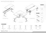
ASSEMBLY OVERVIEW
8-pin DIN-sockets
7-pin DIN-socket
Drive 1 Drive 2
Attention:
Before starting the system, please make sure,
that the operating voltage of the system
conforms with the local power supply. The
mains plug of the control has to be connected
to a free accessible power supply.
* Plug in - Follow the arrow on the sockets.
Main
Cable
S c en a r i o s H V Fr ame- M ot or ized
Handset
Drive 1
Drive 2
SC EN ARIO S LE GS
BE A M
V E R S ION
Aluminium B ea m
C - l eg
Comb i C - le g
SCENARIOS
RECTANGULAR & HV (MOTORIZED) - ALUMINIUM BEAM
HV version via motorized
www.markantoffice.com
I N S TA L L AT I O N M A N U A L
b.
a.
Allen Key
M6
b.
x4
Bottom view - a. Adjust the length of the beam to fit with worktop,
b. Fix cap screws into beam.
S/D Screw
x4
Bottom view - Attach control panel with S/D screws at the bottom of
the worktop.
x2
CSK Screw
x2
c.
Bottom view - Attach connection plate at the side of the endleg.
Bottom view - Attach endleg into panel - a. Fix cap screw at the
connection plate, b. Fix cap screw at the bottom of the panel,
c. Fix CSK screw at the bottom of the panel.
Attach the removable cover to close the panel.
3
2
Assemble control box ( refer to front page control box assembly ).
1
Down
Place control box in cabletray, tidy up all the cables into the cabletray.
2
Up Down
3
Memory 1,2,3,4
Display
Up Down
4
5
SET TIN G
Up Down
x2
Cap Screw
b.
M3 x 13mm
CONTROL BOX
1
Allen Key
M5
M8 x 25mm
Cap Screw
Cap Screw
x2
Cap Screw
3
2
M6 x 8mm
Bottom view - Place worktop on frame, attach worktop with
JCBC screws from bottom of top support.
1
a.
M6 x 12mm
x 16
M8 x 16mm
JCBC Screw
Hook cabletray hinge into the beam rail.
2
a.
Allen Key
M5
Allen Key
M5
Slide connector into beam.
M6 x 12mm
WORKTOP
1
Display
1
c.
View up-side-down - a. Push plastic stopper (a) away from leg,
b. Push down stopperhead (d) into centre gutter, c. Fit round axis over
hexagon shaft inside connector, d. Pull stopper head out of gutter.
Mount connector to endleg with cap screws.
Memory 1,2,3,4
3
PA NE L
HV VE R SI ON
x2
M8 x 25mm
Cap Screw
2
d.
a.
C A BLE MA N A GE MN E T
1
Store memory
Start up - Turn on the main power supply before setting. Once the
power is on, display flashes show 000 or ---.
Memory 1,2,3,4
Store memory
Handset 62cm - 85cm
Handset
Display
6
Press and hold the down button until the lowest position 062 is reached
(show in display, stop flashing), system is ready for further programming,
the maximum reachable height is 085.
Memory 1,2,3,4
Normal operation - Press and hold up or down until the desired
height of the desk has been reached, the display always shows the
actual height.
Saving preferred height - 4 preferred heights can be saved.
Store memory
Move to the desired desk height. Press the store memory ‘S’. You will
see the display shows ‘S - ‘.
7
PLEASE REFER TO MARKANT
MOTOR CONNECTOR SET
USER MANUAL FOR
HEIGHT ADJUSTABLE DESK
FOR FURTHER HELP
Press one of the memory keys, 1,2,3,4, and the number of the position
height is displayed, a double click is heard at the end of memory saved.
Repeat the same step of this for other preferred heights.
Moving to a saved preferred height - Press and hold one of the
keys, 1, 2, 3, 4, the desk will moves towards to the preferred height.
SCENARIOS
RECTANGULAR & HV (MOTORIZED) - ALUMINIUM BEAM
www.markantoffice.com


![HomeSullivan 405302C-36(3A)[5PC]-24 Instructions / Assembly](http://vs1.manualzilla.com/store/data/006934919_1-e03850bf919880fd79dd10f337eb5deb-150x150.png)