1
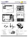
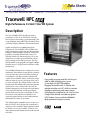
Tracewell
Data Sheets
Systems
567 Enterprise Drive Westerville, OH 43081
1.800.848.4525
phone 614.846.6175
fax 614.846.4450
www.tracewellsystems.com
Tracewell HPC
High-Performance 13-Slot C Size VXI System
Description
The Tracewell HPC VXI is the industry’s highest
performance 13-slot, C size VXI chassis. Featuring
increased power and cooling, system monitoring, and
a rugged modular design, HPC VXI is ideal for the latest
generation of high-performance VXI instrumentation.
Capable of delivering over 3000W through the
backplane, the Tracewell HPC VXI is available with
single or dual power supplies that plug directly into the
backplane, eliminating high-current DC wiring while
providing exceptional dynamic load response. To
efficiently manage this amount of power, the 13-slot
backplane uses a unique power distribution scheme
and special high current DIN connectors. The highflow fan module is also pluggable and supplies 300 cfm
of airflow at 0.125" of H2O board restriction in a fully
loaded chassis.
Tracewell HPC VXI also features comprehensive system
monitoring. This intelligent system provides a warning
to the operator when power and cooling readings go
out of tolerance. The power monitor continuously
verifies all seven VXI DC voltages, and has the unique
ability to notify the user of a past voltage fault even if
it returns to normal. The cooling monitor verifies fan
function and is also available with a temperature monitor
option. In the event a cooling fault is detected, the
monitor shuts down the system to prevent costly damage
to the installed VXI boards. A front panel display
provides local status for power and cooling as well as
other major system functions. In addition, a rear
connector outputs both power and cooling monitor
information for remote site operation.
This VXI plug&play compatible chassis occupies just
10U of rack space and is designed to accommodate a
single tier receiver assembly. Using the optional extender
kit, double-tier receiver assemblies can also be used.
Other options include bottom mounted cable tray and
rack slides.
Features
• Low-profile occupying only 10U of rack space
• 2KW or 4KW plugging power system
• 13-slot high-current VXI backplane
• Plugging fan module with (2) 340 cfm fans
• 300 cfm of airflow at 0.125" of H2O restriction
• Intelligent monitoring with remote output
• VXI plug&play compliant for 1 & 2-tier receivers
• Temperature monitor and cabletray options
• TÜV Product Service certified to EN60950
• High-performance digital test ready
Tracewell
Tracewell HPC
Systems
Data Sheets
Specifications
Physical
Construction:
Cardcage:
Dimensions:
Weight:
Finish:
Cableways:
Rack-Slides:
Cabletray:
Cooling
Sheet aluminum, 5052-H32 alloy; sides (0.125”), top/bottom
covers, HPC-4K power supply cover (0.050”), fan housing (0.062”)
optional 2U cabletray (0.080”)
Sheet steel, ASTM A366; upper/lower cardcages, upper/lower front
cableways/covers, HPC-2K power supply cover (0.060”)
Aluminum extrusion, 6101-T6 alloy; cardcage front and mid
profiles, rack flanges
Cardguide, snap-in, 0.062” pcb thickness, white nylon,
UL 94V-2 flame rated material
Front loading, 6U x 340mm ‘C’ size, 13 slots maximum, IEEE 1101.1
28.15”D (715 mm), 19.0” W (483 mm), 17.47” H (10U; 444 mm)
73 lbs. (33.2 kg; HPC-2K), 85 lbs. (38.6 kg; HPC-4K)
Textured paint, Carbide Black per Sherwin Williams F63B12; all
exterior surfaces; All other aluminum is brushed gold chromate
per MIL-STD 5541, steel is black paint over primer
6 front cableways with covers; (2) upper, (2) lower and 1 per side
Designed to accept General Devices #CTHRS-124 rack slides
Optional 2U cabletray attaches to bottom of unit; capable of
supporting up to 200 lbs. during bench-top operation; includes
mounting hardware;
3U extender kits: two optional 3U extender kits available for mounting single or double-tier Virginia Panel Series 90 receiver frames;
kit includes extended 14U front flanges, 3U side supports and
mounting hardware; can be used with the optional 2U cabletray
Backplane
General:
Bus structure:
Assembly:
Layer count:
Control:
PCB construction:
Impedance:
Termination:
Decoupling:
DC distribution:
Compliance:
13 slot, VXI ‘C’ size monolithic, 96 pin high current DIN connectors
VXI 32 bit
SMT/press-fit assembly
8 layers
Active automatic bus-grant and IACK jumpering, active termination
FR4 epoxy-glass laminate, multilayer, all-stripline, SMOBC, silkscreen
on two sides, 1oz. copper signal and power planes minimum,
UL94V-0, 0.125” (3.18mm) pcb thickness
50 Ohms nominal on all signal lines, non-loaded pcb
Active onboard, electrically inboard; Thevinin equivalent to 194
Ohms at 2.94V
High frequency decoupling at each slot (0.1F SMD ceramic); Bulk
distributed low frequency (100F SMD Tantalum)
High current power midplane distributes power from plugging
power supplies to backplane
VXI-1 Rev. 1.4
Airflow:
Fan:
Air filter:
Accessibility:
Control and Input
Switches:
Reset control:
Front panel: AC on/off (rocker); reset (pushbutton, momentary)
200ms debounced reset to backplane; asserted by front panel
reset switch or VME module; also provides monitor reset
SYSFAIL:
Signal driven only by backplane VME modules; front panel LED is
only a status indicator
Indicators:
Front panel SYSRESET, SYSFAIL DC Fault (red), power and cooling
(tri-color) LED indicators
Power input:
Rear panel AC inlet (IEC320) with fuse drawer, line cord provided
with NEMA L6-20R plug, cord retainer bail
Circuit protection: Rear panel 2-pole magnetic switched circuit breaker; 15A (HPC2K), 20A (HPC-4K)
Monitoring
Option codes M1:
HPC chassis with multi-point, exhaust air temperature monitor
Interface:
Functions:
Front panel LED indicators and rear panel 9-pin status connector
Power: 7 independent voltage monitors for +5, -5.2, -2.2,
+/-12, and +/-24VDC; power fault is generated when any voltage
falls below 90% of nominal; power fault is a latched signal to
record intermittent conditions; power DC Fault monitor (HPC-4K
only); a power fault drives both a front panel LED and rear
panel relay closure
Cooling: verifies RPM and voltage for each fan; cooling fault is
generated if fan speed falls below 50% of nominal or 24V not
present; a cooling fault drives front panel LED, rear panel relay
closure and a system shutdown using global DC inhibit
Optional multi-point, exhaust air temperature (M1): 13 sensors
distributed across top of cardcage monitor exhaust air temperature;
cooling fault generated for air temperature >60oC
Monitor reset: all monitor faults are latching and can be reset by
depressing front panel reset button or by cycling AC power; 5
second delay occurs after any reset prior to further fault detection
Power LED: Green = no fault exists; Red = fault currently exists;
Yellow = intermittent fault occurrence
Cooling LED: Green = no fault exists; Red = system shutdown
due to cooling fault; Yellow = system shutdown due to non-cooling
fault (i.e. loss of fan power)
DC Fault LED: (A and B): power supply global DC OKAY monitor
(red indicates fault; HPC-4K only)
Rear panel 9-pin remote status connector (AMP p/n 747321-4):
Power and cooling faults drive relay closure
(see status connector pinout)
Outputs:
Power†
Option codes PS1: HPC-2K with single 2KW power supply, AC input with PFC
Option codes PS2: HPC-4K with two 2KW power supplies, AC input with PFC
Total output:
Input:
Frequency:
Efficiency:
Power factor:
Input current:
2000W (HPC-2K), 3415W (230V; HPC-4K); maximum all outputs
90 – 264VAC, universal input
47 – 63 Hz
75% typical
0.99 with PFC
15A maximum (12A recommended; HPC-2K),
20A maximum (16A recommended, HPC-4K)
Inrush current:
90V/20A, 190V/29A, 208V/32A, 250V/38A (HPC-2K)
90V/40A, 190V/58A, 208V/64A, 250V/76A (HPC-4K)
Hold-up time:
20 ms minimum after removal of power at full load
ACFAIL:
Logic low signal asserted to backplane after removal of AC power
DC outputs:
HPC-2K: +5V/80A, -5.2V/60A, -2.2V/60A, +/-12V/18A (ea.),
+/-24V/10A (ea.)
HPC-4K: SUPPLY 1 (upper): +/-12V/36.0A (ea.), -2.2V/120A,
+5V/120A; SUPPLY 2 (lower): -5.2V/120A, +/-24V/30A (ea.)
Output adjustment: All outputs are adjusted at factory
Ripple/Noise:
Less than 1% peak-to-peak or 50mV, whichever is greater; bandwidth
limited to 20MHz
Load requirement: 10% minimum load required on + and – 24VDC
Remote sense:
All outputs, 500mV maximum compensation
Inhibit:
Global DC inhibit (wired to front panel switch)
Cooling:
Internal DC fans
567 Enterprise Drive Westerville, OH 43081
1.800.848.4525
Rear intake, top/side exhaust, ducted plenum, pressurized
(2) 340 cfm, high-pressure tube-axial, 24VDC
Front accessible, washable media, 30 PPI, tool accessible
Rear removable plugging module; tool accessible (philips driver)
Environmental
Temperature:
0 – 50oC operating; -20 – 70oC non-operating
Shock/ Vibration: Basic transportation per ASTM 0775
Humidity:
5 – 95% non-condensing at 40oC operating, 0 – 95% nonoperating
Acoustic:
<68 dBa (1 meter)
Agency Compliance††
Safety:
Emissions:
TÜV Product Service certified to EN60950; #B 98 11 32557 003
See note below
Warranty
1 year limited warranty
phone 614.846.6175
fax 614.846.4450
www.tracewellsystems.com
Tracewell
Data Sheets
Tracewell HPC
Systems
Drawings
Main Assembly
D1
Front Panel Detail
D2
DC FAIL
ON
SYSFAIL
COOLING
POWER
PS 1
PS 2
STBY
Side Cableway (2x)
Receiver
Mounting
Rack-slide Mounting
Upper/Lower Cableway (4x)
Front View
Left-side View
W1
Air Exhaust
W2
LINE INPUT
(OFF)
CIRCUIT BREAKER
(ON)
STATUS
250V 6.2A T
AC Inlet
CAUTION:
1) DISCONNECT AC POWER BEFORE SERVICING.
2) AUXILIARY POWER OUTLETS (REFER TO USER MANUAL FOR INTENDED USE).
AC Outlets (2x)
Circuit Breaker
Power Supply 1
Status Connector
Power Supply 2
Air Filter Access (2 screws)
Fan Module
1
H1
H2
Air Intake
2
Rear View
Right-side View (internal)
Sub-Assemblies and Options
4
H1
D3
H3
3
W3
D4
W1
13U Adapter Kit
Cabletray (2U) Kit
Status Connector Pinout:
PIN
1
2
3
4
5
6
7
8
9
FUNCTION
Chassis Ground
Low Voltage NC Relay
Low Voltage NC Relay
Low Voltage NO Relay
Low Voltage NO Relay
Airflow Shutdown NC Relay
Airflow Shutdown NC Relay
Airflow Shutdown NO Relay
Airflow Shutdown NO Relay
Rear Accessible Fan and Power Modules
Dimensions:
Front Panel Detail:
DC FAIL
ON
SYSFAIL
RESET
H1: 17.47" (444 mm)
W2: 16.61" (422 mm)
H2: 6.00" (153 mm)
D3: 12.09" (307 mm)
W3: 15.56" (395 mm)
H3: 3.05" (78 mm)
Notes:
POWER
567 Enterprise Drive Westerville, OH 43081
W1: 19.00" (483 mm)
D2: 27.52" (699 mm)
D4: 23.18" (589 mm)
PS 1
COOLING
D1: 28.15" (715 mm)
PS 2
(4K only)
1.800.848.4525
STBY
1
Lower cross member moves down for 13U adapter kit
2
Do not obstruct intake or exhaust vents
3
Power supply cover removes with (12) 6-32 screws
4
Disconnect AC power prior to service
phone 614.846.6175
fax 614.846.4450
www.tracewellsystems.com
Tracewell
Data Sheets
Systems
567 Enterprise Drive Westerville, OH 43081
1.800.848.4525
phone 614.846.6175
fax 614.846.4450
www.tracewellsystems.com
Tracewell HPC
Call Us!
Ordering Information
The Tracewell HPC VXI includes chassis, backplane, power supply, cooling
and monitoring per the following standard configurations:
Part number
590-1006-F00-01
590-1006-F00-02
590-1003-F01-01
590-1003-F01-02
Description
HPC-2K chassis with 2KW power system (PS1)
HPC-2K chassis with 2KW power system (PS1), multi-point temperature monitor (M1)
HPC-4K chassis with 4KW power system (PS2)
HPC-4K chassis with 4KW power system (PS2), multi-point temperature monitor (M1)
Accessories
106-1006-099-01
590-1105-C00-00
590-1102-C00-00
590-1101-C00-00
Non-shielded single-slot filler panel, 6U X 8T; installs in vacant slots
13U adapter kit for single-tier Virginia Panel Series 90 receiver
13U adapter kit for double-tier Virginia Panel Series 90 receiver
Cabletray (2U) kit
Notes:
†
The HPC product line is specially designed for use with Teradyne M9xx high-performance VXI digital test modules.
These modules require a VXI backplane voltage setting of -2.2Vdc for proper operation. All HPC chassis part numbers
above are shipped with this -2.2V output setting. As an order option, Tracewell can provide HPC chassis pre-configured
with the VXI specified -2.0Vdc output for applications that do not use Teradyne M9xx modules and specifically require
the VXI specified output. Please contact the factory for more details.
The HPC VXI utilizes a unique plugging power design to achieve the power performance referenced above.
These module power supplies, although similar in appearance, are not interchangeable between versions.
Mechanical measures have been taken to prevent accidental installation across versions.
††
Emissions information is available for the power supplies only. As an option, Tracewell Systems can
evaluate agency compliance for the customer’s specific integrated product. Consult factory for more details.
visit our website at:
www.tracewellsystems.com
or call toll free: 1.800.848.4525
©Copyright Tracewell Systems, Inc. 2006
Tracewell Systems, Inc. reserves the right to make changes without notice.
All brand or product names may be trademarks or registered trademarks of their respective holders.
Please consult your Tracewell Systems sales contact for any special or custom requirements.
P/N 095-6006 060208