1
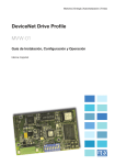
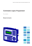
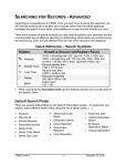
Motors | Automation | Energy | Transmission & Distribution | Coatings
DeviceNet Drive Profile
CFW-09
Communication Manual
DeviceNet Drive Profile Communication Manual
Serie: CFW-09
Language: English
Software Version: V4.4X
Document Number:10000279147 / 01
05/2011
www.weg.net
SUMMARY
1 INTRODUCTION.............................................................................................................. 7
2 FIELDBUS KIT ................................................................................................................. 8
3 INTRODUCTION TO THE DEVICENET NETWORK....................................................... 9
3.1 CABLE AND CONNECTOR ........................................................................................................................9
3.2 LINE TERMINATOR ....................................................................................................................................9
3.3 BAUDRATE AND NODE ADDRESS...........................................................................................................9
3.4 INDICATION LEDS....................................................................................................................................10
3.5 CONFIGURATION FILE (EDS FILE) .........................................................................................................10
4 DEVICENET DRIVE PROFILE COMMUNICATION PARAMETERS ............................ 11
5 CONTENTS OF THE I/O WORDS................................................................................. 14
5.1 DATA CONTENTS FOR THE INSTANCES 20 / 70..................................................................................14
5.1.1 Writing Words (Instance 20)...........................................................................................................14
5.1.2 Reading Words (Instance 70).........................................................................................................15
5.2 DATA CONTENTS FOR THE INSTANTES 21 / 71 ..................................................................................15
5.2.1 Writing words (instance 21) .........................................................................................................15
5.2.2 Reading Words (Instance 71).........................................................................................................16
5.2.3 Speed Reference for the Instances 20 and 21 ...............................................................................17
5.2.4 Motor Speed for the Instances 70 and 71 .....................................................................................17
5.3 DATA CONTENTS FOR THE INSTANCES 100/101................................................................................17
5.3.1 Writing Words (Instance 100)) ........................................................................................................18
5.3.2 Reading Words (Instance 101).......................................................................................................18
5.4 DATA CONTENTS FOR THE INSTANCES 102/103................................................................................18
5.4.1 Selection of the Number of I/O Words ...........................................................................................18
5.4.2 Writing Words (Instance 102).........................................................................................................18
5.4.3 Reading Words (Instance 103).......................................................................................................19
5.5 WEG CONTROL WORD............................................................................................................................19
5.6 WEG SPEED REFERENCE .......................................................................................................................20
5.7 WEG STATUS WORD ...............................................................................................................................20
5.8 WEG MOTOR SPEED ...............................................................................................................................20
5.9 P347: COMMAND FOR THE DIGITAL OUTPUTS...................................................................................20
5.10 SOFTWARE ERRORS .............................................................................................................................21
6 COMMUNICATION ERRORS ....................................................................................... 22
6.1 E29: INACTIVE FIELDBUS COMMUNICATION ......................................................................................22
6.2 E30: INACTIVE FIELDBUS BOARD .........................................................................................................22
www.weg.net
1 INTRODUCTION
This manual provides the necessary information for the operation of the CFW-09 frequency inverter using the
DeviceNet Drive Profile Anybus-S communication module. This communication module makes available at the
product a communication interface for the DeviceNet network with the following characteristics:
■ It makes the inverter parameterization through the network possible with direct access to the parameters via
messages sent by the master.
■ It follows the Device Profile for AC and DC Drives standard, specified by the ODVA (Open DeviceNet Vendor
Association), which defines a set of common objects for drives that operate in a DeviceNet network.
This manual brings an overview of the DeviceNet Network operation, focusing mainly on the inverter
parameterization and operation in this network. The protocol detailed description can be obtained with the
ODVA.
This manual must be used together with the CFW-09 user manual.
DeviceNet Drive Profile l 7
www.weg.net
2 FIELDBUS KIT
A KFB-DD kit (part number 417102542) containing four items is supplied for the communication with the
DeviceNet network:
■ DeviceNet Drive Profile communication board;
■ Cable with a network connector;
■ EDS network configuration file;
■ Installation manual.
8 l DeviceNet Drive Profile
www.weg.net
3 INTRODUCTION TO THE DEVICENET NETWORK
The DeviceNet communication is used in industrial automation, normally for the control of valves, sensors, I/O
units and automation equipments. The DeviceNet communication link is based on a CAN (Controller Area
Network) communication protocol. The next figure brings an overview of a DeviceNet network.
Figure 1: DeviceNet network
3.1 CABLE AND CONNECTOR
The DeviceNet network uses a shielded copper cable with two twisted pairs, being one of the pairs responsible
for the 24 Vdc supply distribution, and the other for the communication signal. An example of connector for the
CFW-09 is showed next, together with the color codes used for the connection:
1
2
3
4
5
Black
Blue l
Shield
White
Red
VCANL
SHIELD
CANH
V+
Figure 2: DeviceNet network connector
The maximum current consumption for the 24Vdc power of DeviceNet interface is 30mA.
3.2 LINE TERMINATOR
The initial and final points of the network must be ended with the characteristic impedance in order to avoid
reflections. Therefore, a 120 Ω/0.5 W resistor must be connected between the pins 2 and 4 of the connector.
3.3 BAUDRATE AND NODE ADDRESS
There are three different Baudrates for DeviceNet: 125 k, 250 k or 500 kbits/s. The selection is done through
DIP switches existent on the communication board. The node address is selected through six DIP switches also
present on the electronic board, allowing addresses from 0 to 63.
Figure 3: Address and baudrate configuration
DeviceNet Drive Profile l 9
www.weg.net
NOTE!
The inverter baudrate and address in the network are updated only during the inverter power on.
3.4 INDICATION LEDS
The communication board has four indication LED’s for network diagnosis, with the following functions:
Figure 4: Communication board status LED’s
Table 1: Signalization of the communication board status LED’s
LED
Host Communication Status
Network Status
Module Network Status
Color
Description
Green
Data exchange between the board and the inverter is OK
Red
Failure in the data exchange between the board and the inverter (permanent))
Flashing Red
Failure in the data exchange between the board and the inverter (temporary)
Off
Without supply/off line
Green
Operative link, connected
Red
Link critical fault (double address, buss off)
Flashing Green
On line, not connected
Flashing Red
Connection Time out
Off
Without supply
Red
Unrecoverable fault
Green
Operational board
Flashing Red
Minor fault
3.5 CONFIGURATION FILE (EDS FILE)
Each element in a DeviceNet network is associated to an EDS file, which contains all the information about this
element. This file is used by the network configuration program during its configuration. Use the file with the
.EDS extension supplied together with the fieldbus kit.
NOTE!
For this firmware version it is possible to program the master communication with the communication
board in different connection types: Polled or Change of State & Cyclic.
10 l DeviceNet Drive Profile
www.weg.net
4 DEVICENET DRIVE PROFILE COMMUNICATION PARAMETERS
The parameters used for the configuration of the DeviceNet interface using the DeviceNet Drive Profile
communication board are described next.
Parameter
P309
Fieldbus
Range
[Factory Setting]
Unit
0 to 10
[0]
-
Description
■ It allows programming the Fieldbus interface to be used,
according to the following options:
Table 2: Fieldbus options
Value
Description
0
Inactive
1
Profibus DP/DP-V1 2 I/O
2
Profibus DP/DP-V1 4 I/O
3
Profibus DP/DP-V1 6 I/O
4
DeviceNet 2 I/O
5
DeviceNet 4 I/O
6
DeviceNet 6 I/O
7
EtherNet/IP 2 I/O
8
EtherNet/IP 4 I/O
9
EtherNet/IP 6 I/O
10
DeviceNet Drive Profile
■ In order to use the DeviceNet Drive Profile communication
board, it is necessary to program the option 10 at P309.
P335
DeviceNet I/O
Instances
0 to 3
[0]
-
■ It allows programming the I/O instances used by the
DeviceNet Drive Profile interface. These instances define
the contents and the quantity of I/O words exchanged
with the network master.
Table 3: DeviceNet I/O instances
Value
0
Description
Instances 20/70
1
Instances 21/71
2
Instances 100/101
3
Instances 102/103
■ The contents of the I/O words for each of the instances
are described in the section 5.
■ The modification of this parameter only becomes valid
after cycling the power of the inverter.
DeviceNet Drive Profile l 11
www.weg.net
Parameter
P336
Write Parameter
#3
P337
Write Parameter
#4
P338
Write Parameter
#5
P339
Write Parameter
#6
Range
[Factory Setting]
Unit
0 to 749
[0]
0 to 749
[0]
0 to 749
[0]
0 to 749
[0]
0 to 749
[0]
-
Description
■ The parameters P336 to P340 permit to program the
content of the output words 3 to 7 (output: the master
sends to the inverter). Using these parameters it is
possible to program the number of another parameter
whose content must be made available at the network
master output area.
■ For instance, if one wishes to write the acceleration ramp
value in the CFW-09 inverter, one must program the value
100 in one of these parameters, because the parameter
P100 is the one where this data is programmed. It is
worthwhile to remind that the value read from any
parameter is represented with a 16 bit word with sign, in
two’s complement. Even if the parameter has decimal
resolution, the value is transmitted without the indication
of the decimal places. E.g., if one wishes to write value
5.0 s in the parameter P100, the value programmed via
the network must be 50.
■ These parameters are used only if the inverter were
programmed for use the I/O instances 102/103, and if the
number of Input/output words programmed in P346 were
greater than 2.
P340
Write Parameter
#7
■ The first two input words are fixed and represent the
control and the speed reference.
P341
Read
Parameter #3
P342
Read
Parameter #4
P343
Read
Parameter #5
P344
Read
Parameter #6
0 to 749
[0]
0 to 749
[0]
0 to 749
[0]
0 to 749
[0]
0 to 749
[0]
-
P345
Read
Parameter #7
12 l DeviceNet Drive Profile
■ The parameters P341 to P345 permit to program the
content of the input words 3 to 7 (input: the inverter sends
to the master). Using these parameters it is possible to
program the number of another parameter whose content
must be made available at the network master input area.
■ If for instance one wants to read from the CFW-09 inverter
the motor current in Amps, one must program the value 3
in one of these parameters, because the parameter P003
is the one that contains this information. It is worthwhile to
remind that the value read from any parameter is
represented with a 16 bit word with sign, in two’s
complement. Even if the parameter has decimal
resolution, the value is transmitted without the indication
of the decimal places. E.g., if the parameter P003 has the
value 4.7 A, the value supplied via the network will be 47.
■ These parameters are used only if the inverter were
programmed for using the I/O instances 102/103, and if
the number of Input/output words programmed in P346
were greater than 2.
■ The first two input words are fixed and represent the
status and the motor speed.
www.weg.net
Parameter
P346
Number of I/O
words
Range
[Factory Setting]
Unit
2 to 7
[2]
-
Description
■ If the option 3, instances 102/103, is programmed in
P335, it will be possible to program in P346 the number of
words exchanged with the master from 2 up to 7 words.
■ The first two input and output words are fixed, as
explained in the section 5. The other words are
programmed in the parameters from P336 to P345.
■ The modification of this parameter only becomes valid
after cycling the power of the inverter.
DeviceNet Drive Profile l 13
www.weg.net
5 CONTENTS OF THE I/O WORDS
The CFW-09 DeviceNet Drive Profile communication board has four different data formats that can be mapped
for the inverter I/O area (assembly instances). These instances are defined by P335, and the first two options
follow the Drive Profile model defined by the ODVA, and the two others are WEG specific. The number of I/O
words as well as the contents of each word is summarized in the next table.
Instances
Number of
(P335)
Input/Output Words
20 / 70
2
21 / 71
2
100 / 101
2
2 ... 7
102 / 103
Defined through
P346
Output Area Data
Input Area Data
word 1 = control
word 1 = status
word 2 = speed reference
word 2 = motor speed
word 1 = control
word 1 = status
word 2 = speed reference
word 2 = motor speed
word 1 = control (WEG)
word 1 = status (WEG)
word 2 = speed reference (WEG)
word 2 = motor speed (WEG)
word 1 = control (WEG)
word 1 = status (WEG)
word 2 = speed reference (WEG)
word 2 = motor speed (WEG)
The other words are defined by the
The other words are defined by the
parameters P336, P337, P338, P339
parameters P341, P342, P343, P344
and P340
and P345
Drive
Profile
ODVA
ODVA
WEG
WEG
5.1 DATA CONTENTS FOR THE INSTANCES 20 / 70
By programming P335 = 0 (20/70), the inverter will automatically make available at the I/O area two writing
words (output) and two reading words (input), with the following contents:
Input (inverter →
Output (master → inverter)
master)
Instance 20
Instance 70
Control word
1st word
Status Word
Speed reference
2nd word
Motor Speed
5.1.1 Writing Words (Instance 20)
1 = Control word
The control word is formed by 16 bits, where each bit has the following function:
Bit number
Bit = 0
0
Stop
1
Reserved
2
No function
3 ... 15
Bit = 1
Run
Error reset
Reserved
■ Bit 0: Run
Bit 0 = 0: It sends the command to stop the inverter via ramp.
Bit 0 = 1: It sends the command for enabling via ramp (run the motor).
Note: This command only works if the inverter is programmed to be commanded via fieldbus (refer to
the parameters P224 and P227).
■ Bit 2: Error reset
Bit 2 = 0: It does not reset the errors.
Bit 2 = 1: It sends the command to reset the inverter errors.
2 = Speed reference
Refer to the section 5.2.3 - Speed Reference for the Instances 20 and 21.
14 l DeviceNet Drive Profile
www.weg.net
5.1.2 Reading Words (Instance 70)
1 = Status word
The status word is formed by 16 bits, where each bit has the flowing function:
Bit number
Bit = 0
Bit = 1
0
Without error
1
Reserved
2
Stopped
3 ... 15
Reserved
With error
Running
■ Bit 0: Error
Bit 0 = 0: The inverter is not in error state.
Bit 0 = 1: The inverter is with an active error.
■ Bit 2: Running
Bit 2 = 0: The inverter is stopped.
Bit 2 = 1: The inverter is running the motor.
2 = Motor speed
Refer to the section 5.2.4 - Motor Speed for the Instances 70 and 71
5.2 DATA CONTENTS FOR THE INSTANTES 21 / 71
By programming P340 = 1 (21/71), the inverter will automatically make available at the I/O area two writing
words (output) and two reading words (input), with the following contents:
Output (master -> inverter)
Input (inverter -> master)
Instance 21
Instance 71
Control word
1st word
Status Word
Speed reference
2nd word
Motor speed
5.2.1 Writing words (instance 21)
1 = Control word
The control word is formed by 16 bits, where each bit has the following function:
Bit number
Bit = 0
Bit = 1
0
Stop
1
Stop
Run reverse
2
No function
Error reset
3
Reserved
4
Reserved
5
Local Control
6
Reserved
7 ... 15
Reserved
Run forward
Control via network
■ Bit 0: Run forward
Bit 0 = 0: It sends the command to stop the inverter via ramp. At the end of the ramp the general
disabling of the inverter is also executed.
Bit 0 = 1: It sends the command for general enabling and ramp enabling in forward direction.
Note: This command only works if the inverter has been programmed to be commanded via fieldbus
(refer to the parameters P224 and P227).
■ Bit 1: Run reverse
Bit 1 = 0: It sends the command to stop the inverter via ramp. At the end of the ramp the general
disabling of the inverter is also executed.
Bit 1 = 1: It sends the command for general enabling and ramp enabling in reverse direction.
Note: This command only works if the inverter has been programmed to be commanded via fieldbus
(refer to the parameters P224 and P227).
DeviceNet Drive Profile l 15
www.weg.net
■ Bit 2: Error reset
Bit 2 = 0: It does not reset the errors.
Bit 2 = 1: It sends the command to reset the inverter errors.
Note: After an error reset the inverter will loose the control and the reference via network (bits 5 and 6),
being necessary to reset these bits in order to write again the desired values.
■ Bit 5: Control via network
Bit 5 = 0: It sends a command for the inverter to operate in local mode.
Bit 5 = 1: It sends a command for the inverter to operate in remote mode.
Note: In order that the inverter be controlled via the DeviceNet network in remote mode, it is necessary
that the option “Fieldbus” be programmed in the operation mode configuration parameters, P220 to
P228.
2 = Speed reference
Refer to the section 5.2.3 - Speed Reference for the Instances 20 and 21
5.2.2 Reading Words (Instance 71)
1 = Status word
The status word is formed by 16 bits, where each bit has the flowing function:
Bit number
0
Bit = 0
Without error
Bit = 1
With error
1
No function
Warning
2
Stopped
Running forward
3
Stopped
Running reverse
4
No function
Ready
5
Local control
Control via network
6
Local reference
Reference via network
7
The reference has not been Running at the speed reference
reached
8 ... 15
value
Inverter status
■ Bit 0: Error
Bit 0 = 0: The inverter is not in error state.
Bit 0 = 1: The inverter is with an active error.
■ Bit 1: Warning
The CFW-09 does not have warning indications.
■ Bit 2: Running forward
Bit 2 = 0: The inverter is stopped.
Bit 2 = 1: The inverter is running the motor in the forward direction.
■ Bit 3: Running reverse
Bit 2 = 0: The inverter is stopped.
Bit 2 = 1: The inverter is running the motor in the reverse direction.
■ Bit 4: Ready
Bit 4 = 0: The inverter is initializing or in error condition.
Bit 4 = 1: The inverter has been initialized and it is without error.
■ Bit 5: Control via network
Bit 3 = 0: The inverter is in local mode.
Bit 3 = 1: The inverter is in remote mode.
Note: P220, P226, P227 and P228 must be programmed for “Fieldbus”, so that this bit does really
represent the control done via fieldbus.
■ Bit 6: Reference via network
Bit 6 = 0: The inverter is not using the reference received via network.
Bit 6 = 1: The inverter is using the reference received via network.
16 l DeviceNet Drive Profile
www.weg.net
■ Bit 7: Running at the speed reference value
Bit 7 = 0: The inverter is not running the motor at the indicated reference value.
Bit 7 = 1: The inverter is running the motor at the speed reference value.
Note: The inverter considers an error of 0.5 % of the synchronous speed in order to analyze whether or
not the motor is running at the reference value.
■ Inverter status: It is a byte that can assume the following values:
Byte value
Meaning
0
Specific of the manufacturer
1
Initializing
2
Not ready
3
Ready
4
Enabled
5
Stopping
Note
Not used
It detects it only If the command was issued via
network
6
Stopped by error
7
With error
The inverter does not have this state
2 = Motor speed
Refer to the section 5.2.4 - Motor Speed for the Instances 70 and 71.
5.2.3 Speed Reference for the Instances 20 and 21
The speed reference for the instances 20 and 21 (output) is received by the inverter in form of an integer with
sign (in two’s complement). Each unit represents 1 rpm, and the negative values are interpreted by the inverter
as reference for rotating in the reverse direction. E.g.:
1200 = 04B0hex = 1200 rpm with forward speed direction
-1200 = FB50hex = 1200 rpm with reverse speed direction
NOTE!
■ The reference value will only be used by the inverter if it has been programmed to receive the
reference via fieldbus (refer to parameters P221 and P222).
■ Negative values will only change the speed direction if it has been programmed to be commanded via
fieldbus (refer to parameters P223 and P226).
■ It is necessary that the sent values respect the minimum and maximum limits permitted for the
reference, which are programmed in the parameters P133 and P134.
■ If a negative reference value were sent together with a command to rotate in the reverse direction, the
inverter will run the motor in the forward direction.
5.2.4 Motor Speed for the Instances 70 and 71
The speed that the inverter is running the motor is transmitted by the inverter in form of an integer with sign (in
two’s complement). Each unit represents 1 rpm, and the positive values indicate that the motor is running in the
forward direction, whereas the negative values indicate that the motor is running in the reverse direction. E.g.:
1800 = 0708hex = the motor is running at 1800 rpm in the forward speed direction
-1800 = F8F8hex = the motor is running at 1800 rpm in the reverse speed direction
5.3 DATA CONTENTS FOR THE INSTANCES 100/101
By programming P335 = 2 (100/101), the inverter will be operating in a WEG specific mode. There will also be
made available two writing words (output) and two reading words (input) for the I/O area, with the following
contents:
Output (master -> inverter)
Instance 100
WEG control word
WEG speed reference
1st word
2nd word
Input (inverter -> master)
Instance 101
WEG status Word
WEG motor speed
DeviceNet Drive Profile l 17
www.weg.net
5.3.1 Writing Words (Instance 100))
1 = WEG control word
It is the word, through which commands are sent to the inverter via the network. In order to know this word
structure, refer to the section 5.5 - WEG control word.
2 = WEG speed reference
It is the fieldbus speed reference word for the inverter. In order to know this word structure, refer to the section
5.6 - WEG speed reference.
5.3.2 Reading Words (Instance 101)
1 = WEG status word
It is the word, through which the inverter indicates its status to the network. In order to know this word
structure, refer to the section 5.7 - WEG status word.
2 = WEG motor speed
It is the word with the actual motor speed. In order to know this word structure, refer to the section 5.8 - WEG
motor speed.
5.4 DATA CONTENTS FOR THE INSTANCES 102/103
The number of words and the contents of the I/O area data for the instances 102 (output) and 103 (input) is
configurable by the user through the parameters P336 to P346.
5.4.1 Selection of the Number of I/O Words
The number of I/O words for the instances 102/103 is selected through P346. It is possible to program from 2
up to 7 words, and the number of reading words (input) will always be equal to the number of writing words
(output).
The first two reading and writing words have pre-defined functions, and the others are programmable,
according to the next table.
Output (master -> inverter)
Input (inverter -> master)
Instance 102
WEG control word
WEG speed reference
Instance 103
1st word
WEG status Word
2nd word
WEG motor speed
3rd word
Function defined by the parameters P336,
P337, P338, P339 and P340
4th word
5th word
6th word
Function defined by the parameters P341,
P342, P343, P344 and P345
7th word
5.4.2 Writing Words (Instance 102)
1 = WEG control word
It is the word, through which commands are sent to the inverter via the network. In order to know this word
structure, refer to the section 5.5 - WEG control word.
2 = WEG speed reference
It is the fieldbus speed reference word for the inverter. In order to know this word structure, refer to the section
5.6 - WEG speed reference.
3 to 7 = Programmable parameters
The words 3 to 7 are programmable, and each word represents a parameter, whose number is selected by the
parameters from P336 to P340. It is possible to program in these parameters the number of another parameter,
whose contents will be made available at the master output area.
For instance, if one wishes to send the acceleration ramp value at the third writing word, it is only necessary to
program P336 = 100, because P100 is the parameter that permits to program the time used by the acceleration
ramp.
18 l DeviceNet Drive Profile
www.weg.net
5.4.3 Reading Words (Instance 103)
1 = WEG status word
It is the word, through which the inverter indicates its status to the network. In order to know this word
structure, refer to the section 5.7 - WEG status word.
2 = WEG motor speed
It is the word with the actual motor speed. In order to know this word structure, refer to the section 5.8 - WEG
motor speed.
3 to 7 = Programmable parameters
The words 3 to 7 are programmable, and each word represents a parameter, whose number is selected by the
parameters from P341 to P345. It is possible to program in these parameters the number of another parameter,
whose contents will be made available at the master input area.
For instance, if one wishes to read the value of the motor current in Amps at the third writing word, it is only
necessary to program P341 = 3, because P003 is the parameter that contains this information of the motor
current.
NOTE!
■ The parameters P204, P215 and P408 are not available for communication.
■ The parameters mapped for writing have their values constantly updated by the network, but they are
not stored in the nonvolatile memory (EEPROM), so that they are restored to their previous value in
case of an inverter reset.
■ The content of each parameter is transmitted as a 16 bit word representing an integer, and in order to
interpret the transmitted and received values correctly, it is necessary to observe the number of
decimal places used at the parameter. For instance, for a 5.0 s acceleration time (P100), since we
have one decimal place resolution, the actual value to be transmitted with the word is 50 (0032hex).
■ For the list of inverter existent parameters, refer to the user manual.
5.5 WEG CONTROL WORD
It is a word accessible only via fieldbus, through which commands to the inverter are sent via the network. It is
formed by 16 bits where each one has the following function:
Bit number
Bit = 0
Bit = 1
0
Ramp disabling
Ramp enabling
1
General disabling
General enabling
2
Reverse speed direction
Forward speed direction
3
JOG Disabling
JOG enabling
4
Local
Remote
5
Reserved
6
Reserved
7
No reset
Error reset occurs
8
9
Inactive command
Inactive command
General enabling mask
10
Inactive command
Speed direction mask
11
Inactive command
JOG command mask
12
Inactive command
Local/remote command mask
13
Reserved
14
Reserved
15
Inactive command
Ramp enabling mask
Reset command mask
The control word has the 8 high order bits responsible for enabling each of the commands sent through the 8
low order bits. If the mask (at the high order bits) is enabled, the inverter will execute the command indicated in
the correspondent low order bit. If the mask is disabled, the inverter will disregard the command sent at the
correspondent low order bit.
In order to enable the functions of the Control Word, it is necessary to set the inverter respective parameters
with the option “Fieldbus”:
DeviceNet Drive Profile l 19
www.weg.net
■ Local/Remote Selection Source - P220;
■ FWD/REV Selection - P223 and/or P226;
■ General enabling, Start/stop Selection - P224 and/or P227;
■ JOG Selection - P225 and/or P228.
5.6 WEG SPEED REFERENCE
It is a word accessible only via fieldbus, through which the inverter receives the speed reference value from the
network. This variable is represented using a 13 bit resolution for the motor synchronous speed. Therefore, the
8191(1FFFhex) reference value will correspond to the motor synchronous speed (equal to 1800 rpm for a 4 pole
motor in a 60 Hz line). It is possible to send values higher than the synchronous speed (greater than 13 bits),
provided that the value sent to the inverter be within minimum and maximum speed reference limits
programmed at the inverter (P133 and P134).
The speed reference value is always positive. In order to invert the speed direction, the bits 2 and 10 of the
Control Word must be used. In order that the reference be accepted by the inverter, it is necessary to program
the parameters P221 and/or P222 with the “Fieldbus” option.
5.7 WEG STATUS WORD
It is a reading word where the inverter status is indicated, and accessible only via fieldbus. It is formed by 16 bits
divided into 8 low order bits that indicate the error code, and the 8 high order bits indicating the status of the
inverter:
Bit number
0 ... 7
Bit = 0
Bit = 1
Error code
8
Ramp disabled
9
General disabled
Ramp enabled
General enabled
10
Reverse speed direction
Forward speed direction
11
JOG disabled
JOG enabled
12
Local
Remote
13
Without undervoltage
With undervoltage
14
PID Regulator– Manual
PID Regulator– Automatic
15
Without error
With error
When the status word bit 15 is active (indicating inverter with error), the eight low order bits will indicate the error
code, which can be a hardware error (refer to the inverter manual section 7.1 – Faults and Possible Causes), or
a software error (Refer to the section 5.10 - Software errors).
5.8 WEG MOTOR SPEED
It is a reading word that makes the motor speed reading possible. This variable is showed using a 13 bit
resolution with signal (in two’s complement). Therefore, the nominal value will be equal to 8191(1FFFhex) (forward
rotation) or – 8191(1FFFhex) (reverse rotation) when the motor is running at the synchronous speed (or base
speed, for instance 1800 rpm for a 4 pole motor in a 60 Hz line). The 13 bit value is used only as base for the
representation, speed values greater than 13 bits can also be indicated.
5.9 P347: COMMAND FOR THE DIGITAL OUTPUTS
The P347 is a special parameter, accessible only through the fieldbus interface, which makes it possible to
command the inverter digital outputs. This parameter has 16 data bits, divided into 8 high order bits and 8 low
order bits, with the following structure.
20 l DeviceNet Drive Profile
www.weg.net
Bit number
0
Bit = 0
Bit = 1
Inactive DO1 output
Active DO1 output
1
Inactive DO2 output
Active DO2 output
2
Inactive RL1 output
Active RL1 output
3
Inactive RL2 output
Active RL2 output
4
Inactive RL3 output
Active RL3 output
5
Reserved
6
Reserved
7
Reserved
8
Inactive command
9
Inactive command
DO2 command mask
10
Inactive command
RL1 command mask
11
Inactive command
RL2 command mask
12
Inactive command
RL3 command mask
13
Reserved
14
Reserved
15
Reserved
DO1 command mask
In the same way as for the control word, the activation of the digital outputs is also divided into mask (high order
bits) and output values (low order bits). The value for the output will only be updated if the correspondent mask
is active, otherwise it will be disregarded.
In order that the outputs be activated via the network, it is necessary to program P347 at one of the
programmable words in the inverter writing area, besides configuring the parameters regarding the outputs
(P275…P280) for the “fieldbus” option.
5.10 SOFTWARE ERRORS
When the inverter receives an improper command via the network, it indicates some specific errors to the
master, informing which the cause of that error is. These indications appear only at the status word (refer to the
section 5.7 - WEG status word), and are not showed at the inverter HMI. The following error indications may
occur:
■ E24 – Parameter modification allowed only with disabled inverter.
- Programming error (Refer to the section 5.2.3 - Speed Reference for the Instances 20 and 21).
■ E27 – caused by:
- Function selected at the Control Word not enabled for Fieldbus.
DeviceNet Drive Profile l 21
www.weg.net
6 COMMUNICATION ERRORS
Regarding the communication of the inverter with the DeviceNet Drive Profile network, two types of errors may
occur: E29 or E30.
6.1 E29: INACTIVE FIELDBUS COMMUNICATION
The error 29 indicates that some kind of communication problem between the network master and the
communication board has occurred. The main causes of this type of error are:
■ Problems with the communication cable: The cable that connects the network master to the slave may be
broken, some point of it with a contact problem, being without terminator resistors, or having inverted wiring.
■ Master with configuration problems: The network master must be on and configured for communicating with
the inverter.
■ Incorrect number of I/O words: Besides the master being configured to communicate with the inverter, it is
also necessary that the number of input and output words of the master be in accordance with the
programmed at the inverter.
NOTE!
The E29 indication occurs whenever the inverter is not communicating cyclic data. If a master or a
configuration tool that uses only acyclic messages is used, this error will be indicated even if no
communication errors between master and inverter occur.
6.2 E30: INACTIVE FIELDBUS BOARD
The error 30 indicates that a data transfer problem between the communication board and the inverter control
board has occurred. This error is indicated mainly during the inverter initialization. But if after the initialization
problems are identified, this error will also be indicated. The main causes of this error are:
■ Inverter configuration problem: It is necessary to configure P309 correctly for the desired fieldbus option,
according to the type of communication board. It is necessary to program P309 = 10 for DeviceNet Drive
Profile.
■ Board installation problem: If the communication board is not connected or with problems at the bus
connection (bad contact, bent pin), the inverter may indicate this error.
NOTE!
■ If the inverter is being controlled via the fieldbus network when E29 or E30 occurs, then the action
programmed in P313 – Type of disabling by E28/E29/E30 – will be executed.
■ In order to perform the self-tuning routine for the vector mode, it is necessary to disable the
communication at P309.
■ After an E30 indication, it is necessary to cycle the power of the inverter, so that it operates normally
again.
22 l DeviceNet Drive Profile