1
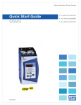
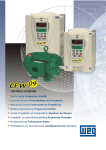
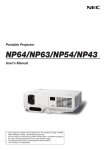
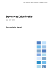
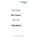
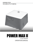
Publication Number QS001CFW09
1 to 75HP (6 to 240A) 230V
1 to 500HP (3.6 to 600A) 460V
2 to 500HP (2.9 to 472A) 575V
For models above 500 HP call 800-ASK-4WEG (800-275-4934)
2
Power Connections and Keypad Operation:
The CFW09 Quick Start Guide is a supplement to help get the CFW09 started quickly using the most common installation
and configuration options. This CFW09 Quick Start Guide is not meant to replace the CFW09 User’s Manual. For detailed
instructions, safety precautions, proper mounting, installation, configuration, and operation please refer to the CFW09
User’s Guide. Warning: Only qualified personnel should plan or implement the installation, start-up, operation and
maintenance of this equipment. Personnel must read the entire CFW09 User’s Guide before attempting to install, operate
or troubleshoot the CFW09.
Figure 1 - Power and Grounding Connections
Key
LED Display –
indicates fault codes,
inverter status,
parameter number and
value.
LCD Display –
2 lines with 16
characters displays
detailed description
of all parameters
and messages.
Green LED - Forward
Green LED - Local
Red LED - Reverse
Red LED - Remote
Figure 2 – Keypad Operation
Display
rdy
run
Sub
dCbr
Display Description
Inverter is Ready to be Enabled
Inverter is Enabled
Power Supply Voltage Too Low for Inverter Operation
Inverter in DC Braking Mode. (See P300)
31
Description
Switches the display between
parameter number and
content.
Jogs motor when pressed
Increases Speed and
Parameter number/content
Decreases Speed and
Parameter number/content
Forward/Reverse Key
Green LED = Forward
Red LED = Reverse
Starts the VFD via a
controlled acceleration ramp.
When running switches the
display between “RPM-voltsstatus-torque-Hz-Amps”
Stops the VFD via a
controlled deceleration ramp.
Resets VFD after a fault trip.
Local/Remote Key
Green LED = Local Mode
Red LED = Remote Mode
Basic Wiring:
1. Mount the CFW09 to a flat vertical surface.
2. For three-phase input power connect the incoming power leads to the R, S, and T connections on the power
terminal and connect the GROUND lead to PE on the chassis (Refer to Figure 1). For single-phase input power
connect the power leads to R and S.
3. Connect the motor leads to the U, V, and W connections on the power terminal and connect the GROUND lead to
PE on the chassis (Refer to Figure 1). Note: Only three-phase AC motors can be used.
4. Apply power to the CFW09 inverter and proceed to “Oriented Start-up”. The inverter will display “P201” on the
LED/LCD displays. This is the first parameter in the “Oriented Start-up” mode.
Note: When the inverter is powered up for the first time or when the factory default parameter values are loaded
(P204=5), the “Oriented Start-up” sub-routine is run. This sub-routine requests the user to program some basic
parameters to ensure proper operation and motor protection. The motor and inverter nameplate data is required in
order to set these parameters. See page 6 for an example of motor nameplate data required (P400-P406).
Oriented Start-up:
Action
After power-up, the display shows the
following message.
Press
mode.
to enter the programming
Use
and
the language.
arrow keys to select
Press the
key to save the
selected option and exit the programming
mode.
Press the
parameter.
arrow key to go to the next
Continue in this fashion programming the
remaining parameters for the inverter.
Press
to enter programming mode,
Press
value.
and
Press
again to store the value.
Press
to go to next parameter.
to select a parameter
LED/LCD Display
Description
Language Selection:
0=Portuguese, 1=English, 2=Spanish,
3=German
Enter the programming mode.
Selected Language:
Select language 1 = English
Exit the programming mode.
Inverter Rated Voltage Selection:
0=220V/230V, 1=380V, 2=400V/415V,
3=440V/460V, 4=480V, 5=500V/525V,
6=550/575V, 7=600V, 8=660V/690V
When the last parameter P406 has been stored
and the “UP” key pressed, “RDY” is displayed
on the keypad indicating the inverter is ready to
operate.
Note: To repeat the initial power-up procedure:
Set parameter P204=5 (this loads the factory
default parameters) and follow the “Oriented
Start-up” procedure again. Password for
parameter access P000=5
Repeat procedure until the remaining
motor parameters P400, P401, P403,
P402, P404, and P406 required in the
“Oriented Start-up” have been
programmed.
Note: These are the minimum parameters for a perfect adaptation between inverter and motor. With these parameter
settings you can operate the inverter in “Local” mode via the keypad. This operation mode is recommended for users who
are operating the inverter for the first time without additional control connections. For start-up according to this operation
mode, proceed to step 5 on page 4.
42
Keypad Start/Stop (Local Mode):
5. The inverter should still be powered up with a display of “RDY”. Having completed “Oriented Start-up”, keypad
navigation should now be familiar. Verify parameter P202=0 (Type of Control = V/F 60Hz). This is the factory
default value and should already be set to 0. Note: To change the value of P202 and all other parameters, P000
must first be set to 5 (Password Parameter P000=5).
6. Scroll down to the read only parameter P002 (Motor Speed) and press
to see the speed value.
7. Press the
start key. The motor will accelerate from 0 to 90 RPM (minimum speed), in the clockwise
direction. Note: If the direction of rotation is not correct, switch off the inverter and wait until the capacitors
discharge completely (as long as 10 minutes) and then swap any two wires at the motor output.
8. Press the
key and hold it to increase motor speed.
FWD / REV key to change directions. The green and red LEDs on the left side of the keypad
9. Press the
indicate rotation direction (Fig. 2)
10. Press the
stop key. The motor decelerates to 0 RPM.
11. Press the
key and hold it. The motor accelerates from 0 RPM to the JOG speed set at P122. Release the
key and the motor decelerates down to 0 RPM.
Notes: (1) The “Acceleration Time” and “Deceleration Time” is set at P100 and P101 respectively (Default value is
20sec). If the acceleration current becomes too high, especially at low frequencies (<15Hz), an inverter over-current
(E00 or E05) may occur requiring the Torque Boost at P136 to be decreased. Increase/decrease the content of P136
gradually until an operation with constant current over the entire frequency range is obtained. Refer to P136 in
Chapter 6 of the CFW09 User’s Guide for a full explanation.
(2) If E01 fault occurs during deceleration, increase the deceleration time at P101.
(3) Minimum and Maximum speeds are set at P133 and P134 respectively.
(4) For a complete description of Parameters and Error codes refer to Chapters 6 and 7 in the CFW09 User’s Guide.
Local/Remote Modes (Hand-Off-Auto):
In the previous section the inverter was operated from the keypad (Local Mode).
Note the green local indicator LED on the bottom right of the keypad (Fig.2). For
the factory default programming, the selection of the operation mode
(Local/Remote) is made via the “Local/Remote” key (default is Local). To pass
default of the key to remote, set P220=3. With this setting the inverter will power
up in remote mode. Note the red remote indicator LED on the bottom right of
keypad (Fig. 2). If you wish to use an external Local/Remote switch (Hand-OffAuto) set P220=4, connect the switch to one of the Digital Inputs (DI2-DI6), and
set the corresponding parameter (P264 to 268=1). To always run in Local mode
set P220=0. To always run in Remote mode set P220=1.
2 Wire Start/Stop (Remote Mode):
Parameters:
1. Set DI1 to START/STOP (P263=1).
2. Set P224=1 (DIx) if you want the 2 wire control in local mode.
3. Set P227=1 (DIx) if you want the 2 wire control in remote mode.
Control Wiring: Verify there is a jumper between XC1-8 and XC1-10 or the
inverter will not work. Start/Stop switch is N.O. (normally open) and is
connected as shown in Figure 3.
Figure 3 – 2 Wire Start/Stop
3
5
3 Wire Start/Stop (Remote Mode):
Parameters:
1. Set DI1 to GENERAL ENABLE (P263=2).
2. Set DI3 to START (P265=14). See note below.
3. Set DI4 to STOP (P266=14).
4. Set P224=1 (DIx) if you want the 3 wire control
in local mode.
5. Set P227=1 (DIx) if you want the 3 wire control
in remote mode.
Control Wiring: Verify there is a jumper between XC1-8
and XC1-10 or inverter will not work. “Start” and “Stop”
are momentary push button switches and are connected
as shown in Figure 4. “Start” is a N.O. (normally open)
contact and “Stop” is a N.C. (normally closed) contact.
Note: When initially setting DI3 to START (P265=14) an
E24 (programming) error will occur and the display will
flash until DI4 is set to STOP (P266=14).
Figure 4 - 3 Wire Start/Stop
Operation from Remote Analog Input (Speed Pot):
Parameters:
1. P222=1 (Remote Speed Ref=AI1)
2. P235=0 (Analog Input Signal =0-10Vdc)
Control Wiring: Connect jumper between XC1-13 and XC1-14 or Speed
Pot will not work. Speed Pot value must be ≥ 5KΩ but ≤ 10KΩ at 2W and
is connected as shown in Figure 5.
Dip Switch Settings: Analog Input 1 (AI1) is set at 0-10Vdc (default) by
the S1-2 Dip Switch on the control board (S1-2=OFF). To detect 4-20mA,
set S1-2=ON and set P235=1. Note: S1-1 is for Analog Input 2. See the
CFW09 User’s Guide for full explanation of analog inputs.
Figure 5 – Analog Input with Speed Pot
Fault Codes:
When a fault is detected, the inverter is disabled and the Fault Code is displayed. (Example E01). To restart the inverter
after a fault has occurred, the inverter must be reset. Resetting the inverter can be done by disconnecting and reapplying
AC power (power-on reset), by pressing the “O/RESET” key (manual reset), automatic reset, or via digital inputs. For
details on Reset and a full list and description of Fault Codes please read Chapter 7 in the CFW09 User’s Guide.
64
Parameters Example:
Motor Data (Example)
Power: 5 HP
Rated Speed: 1730 RPM, 4 Pole
Rated Current: 7.9 A
Rated Voltage: 460 V
Frequency: 60 Hz
Cooling: Self-ventilated
Inverter Data (Example)
Line: CFW09
Rated Current: 9 A
Rated Voltage: 380...480 V
Model: CFW090009TGZ
•
The following is a typical list of parameter changes needed using the Motor/Inverter data shown above and the
factory 60Hz default setting (P204=5).
P000=5
P204=5
P201=1
P296=3
P400=460
P401=7.9
P403=60
P402=1730
P404=8
P406=0
P202=0
P100=20
P101=20
P133=90
P134=1730
P205=2
•
Parameter Access (5 = Password)
Loads Factory Default (5 = 60Hz Default) (P204=7 or 8 saves the user’s data)
Language Setting (1 = English)
Inverter Rated Voltage (3 = 440-460V)
Motor Rated Voltage = 460V
Motor Rated Current = 7.9A
Motor Rated Frequency = 60Hz
Motor Rated RPM = 1730
Motor Rated HP = 5HP
Motor Ventilation Type (0=Self Ventilated)
Type of Control = V/F 60Hz
Acceleration Time = 20 seconds
Deceleration Time = 20 seconds
Minimum Speed = 90 RPM
Maximum Speed – 1730 RPM
Display Default = Motor Speed
Local/Remote parameters allow the inverter to be set up to operate from Keypad, Remote Terminal, or a
programmed combination of keypad and terminal inputs.
P220 – Local/Remote Selection
P221 – Local Speed Reference Selection
P222 – Remote Speed Reference Selection
P223 – Local FWD/REV Selection
P224 – Local Start/Stop Selection
P225 – Local Jog Selection
P226 – Remote FWD/REV Selection
P227 – Remote Start/Stop Selection
P228 – Remote Jog Selection
•
Read Only Parameters (P001 – P065) can be used for monitoring and troubleshooting. For a full list and
description please read the CFW09 User’s Guide. By monitoring certain read only parameters, the status of
inputs, outputs, and drive operational values can be determined without the use of any other test equipment.
P001 – Speed Reference
P003 – Motor Current
P004 - used to monitor DC Bus Voltage.
P005 – Motor Frequency
P006 – Inverter Status
P012 (Digital Input Status) – used to monitor digital inputs.
P013 (Relay Output Status) – used to monitor relay outputs.
P014 to P017 and P060 to P065 – used to read the last 10 faults.
P018 to P021 – used to read analog inputs
These are just a few examples of inverter set-up and parameters. Please read the CFW09 User’s Guide for
additional information.
5
7