1
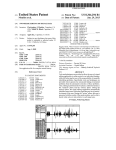
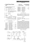
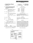
US007672464B2
(12) United States Patent
(10) Patent N0.:
(45) Date of Patent:
Bianchi et al.
(54)
LOCATING AND CORRECTING
UNDESIRABLE EFFECTS IN SIGNALS THAT
REPRESENT TIME-BASED MEDIA
(75) Inventors: Curt Bianchi, Saratoga, CA (US);
Nikhil Bhatt, Cupertino, CA (US);
Christopher Moulios, Cupertino, CA
(Us)
(73) Assignee: Apple Inc., Cupertino, CA (US)
(*)
Notice:
Dec. 8, 2006
Jun. 14, 2007
Continuation of application No. 10/407,900, ?led on
Apr. 4, 2003, noW Pat. No. 7,319,761.
(58)
OTHER PUBLICATIONS
Primary ExamineriVivian Chin
Assistant ExamineriDouglas J Suthers
(74) Attorney, Agent, or FirmiHickman Palermo Truong &
Becker LLP; Daniel D. Ledesma
(57)
ABSTRACT
Int. Cl.
H04R 29/00
H03G 7/00
G06F 17/00
G06F 3/00
G06F 3/16
(52)
6,055,495 A *
6,192,183 B1 *
* cited by examiner
Related US. Application Data
(51)
8/1983 McMann, Jr.
4/2000 Tucker et al. ............. .. 704/210
2/2001 Taniguchi et al. ........... .. 386/52
6,403,871 B2* 6/2002 Shimizu et al. ............. .. 84/622
2003/0014135 A1
l/2003 Moulios
2004/0199277 A1
10/2004 Bianchi et al.
4,398,061 A
Prior Publication Data
US 2007/0135954 A1
(63)
References Cited
Higgins, D., “Wave Corrector v3.0 Vinyl/Tape t0 CD-R Processing
Digital Audio Editing for the PC User Manual,” Jul. 22, 2004,
Ganymede Test & Measurement, v3 .0, from < http://web.archive.0rg/
web/20040722l32002/WWW.Wavecor.co.uk/help300.pdf > (86 pgs).
(21) App1.No.: 11/636,429
Filed:
Mar. 2, 2010
U.S. PATENT DOCUMENTS
Subject to any disclaimer, the term of this
patent is extended or adjusted under 35
U.S.C. 154(b) by 68 days.
(22)
(65)
(56)
US 7,672,464 B2
The invention describes a graphical method for detecting and
adjusting audio overload conditions. The graphical user inter
face provides a user complete playback control of several
audio tracks, detection of overload conditions such as audio
clipping, and graphical methods to correct the overload con
(2006.01)
(2006.01)
(2006.01)
(2006.01)
(2006.01)
US. Cl. ......................... .. 381/56; 381/106; 700/94;
ditions. The graphical interface provides drag handles Which
715/716; 715/727
the user can use to adjust the various characteristics of an
Field of Classi?cation Search ................. ..
381/56,
381/106, 94.8, 94.3; 704/503; 715/727,
715/716; 700/94
See application ?le for complete search history.
135
audio ?le. The characteristics, such as amplitude and tempo,
may be adjusted as a function of time.
23 Claims, 4 Drawing Sheets
US. Patent
Mar. 2, 2010
Sheet 1 M4
US 7,672,464 B2
Figure 1
ii
US. Patent
Mar. 2, 2010
Sheet 2 M4
Figure 2
210
\
US 7,672,464 B2
OBTAIN SIGNAL ABNORMALITY
PATTERN
220
CHECK NEXT SEGMENT
OF AUDIO DATA ABNORMALITY PATTERN
IS
ABNORMALITY PATTERN
FOUND
?
240
ISSUE A VISUAL WARNING
MARK LOCATION OF ABNORMALITY
CHECK FOR END OF AUDIO DATA
IF
US. Patent
Mar. 2, 2010
Sheet 3 0f4
US 7,672,464 B2
Figure 3
310
OBTAIN ABNORMALITIES POSITION
320
DISPLAY SIGNAL AT NEXT
ABNORMALITY POSITION
340
ISSUE A VISUAL WARNING
350
\
360
OBTAIN USER INPUT
APPLY USER INPUT TO AUDIO SIGNAL
AT ABNORMALITY POSITION
US. Patent
h4ar.2,2010
US 7,672,464 B2
Sheet40f4
v2sz
EU
3%
cm005
va
Hg U!
P.
Cww;9%
oQE .
2$8T625938%>
modwm"
as.m;
#2@Q
Nv
ENxumEtD.
US 7,672,464 B2
1
2
LOCATING AND CORRECTING
UNDESIRABLE EFFECTS IN SIGNALS THAT
REPRESENT TIME-BASED MEDIA
FIG. 4 is an illustration of a graphical user interface (GUI)
in accordance with an embodiment of the present invention.
SUMMARY OF THE INVENTION
CROSS-REFERENCE TO RELATED
APPLICATION
An embodiment of the invention is directed to a method
and apparatus for locating overload conditions (e.g., clipping)
in sound ?les and for graphically correcting the overload
This application is a continuation of US. patent applica
tion Ser. No. 10/407,900 ?ledApr. 4, 2003 now US. Pat. No.
7,319,761 which is incorporated herein by reference as fully
set forth herein, under 35 U.S.C. §120.
conditions. The user interface con?gured in accordance with
an embodiment of the invention provides a display region that
comprises a number of graphical components con?gured to
assist the user with the process of determining at what point
during playback of an audio ?le a sound overload condition
occurred. When a sound overload condition is identi?ed,
FIELD OF THE INVENTION
users may then use one of the graphical components within
This invention relates to the ?eld of data processing. More
speci?cally, this invention relates a method and apparatus for
the display region to jump to the point in the audio ?le where
the abnormality exists. This enables users to quickly and
ef?ciently locate and correct any sound overload conditions
locating and correcting sound overload
BACKGROUND OF THE INVENTION
encountered during playback.
20
DETAILED DESCRIPTION
Audio streams recorded as music records, sounds of live
scenes or speech may sometimes contain popping sounds. A
The present invention discloses a method and apparatus for
popping sound is characterized by a short burst of high vol
ume. It is usually introduced by faulty recording equipment,
25
badly adjusted electronic equipment, static electricity or even
following description, numerous speci?c details are set forth
to provide a more thorough description of the present inven
tion. It will be apparent, however, to one skilled in the art, that
incidents happening during the recording session (e. g. colli
sions with a microphone during the recording session). Pop
ping sounds may also be introduced as side effects that
accompany audio data processing using numerical methods.
For example, a numerical manipulation of audio data may
introduce square waveforms that are the origin of the appear
ance of high frequency spikes when the audio stream is
passed through ?lters which are generally present in one form
or another in playback devices.
Popping sounds are usually uncomfortable to the human
ear. It is always desirable to remove popping sounds from
the present invention may practiced without these speci?c
30
Throughout this disclosure, any reference to a user may
alternately refer to a person using a computer application
and/or to one or more automatic processes. The automatic
35
processes may be any computer program executing locally or
remotely, that communicates with embodiments of the inven
tion, and that may be triggered following any predetermined
40
happens. The process may involve digitizing the audio data
that can be used to locate high amplitude that surpasses a
predetermined threshold, then correcting the amplitude at
those locations.
details. In other instances, well known features have not been
described in detail so as not to obscure the present invention.
audio streams, or at least attenuate their amplitude to a level
that does not cause discomfort. A simple way of removing a
popping sound from an audio stream is to reduce the ampli
tude of the audio stream at the location where the popping
locating overload conditions (e.g., clipping) in sound ?les and
for graphically correcting the overload conditions. In the
event. In addition, audio abnormality as used herein generally
refers to saturation of the dynamic range of an audio output
device. Abnormality thus encompasses saturation and its
effects on the resulting audio output.
FIG. 1 is a block diagram that represents the overall layout
of components of a graphical user interface utilized in
embodiments of the invention. One or more graphical user
45
interface (GUI) components (e.g. 120, 130, 140 and 150) are
presented in one or more display areas (e.g. 110: a panel, a
Existing tools for manipulating audio data do not provide
means to visually and easily identify the locations where the
layout container or a graphical window). A system embody
amplitude of an audio stream surpasses a comfortable level of
ing the invention comprises one or more audio data display
listening, and allow the user to interactively alter the audio
stream amplitudes at the affected locations.
components 120. An audio data display component 120
50
Therefore, there is a need for a method for users to graphi
viewing data. For example, component 120 allows a user to
cally indicate locations of audible overload conditions, auto
matically locate those locations, and allow the user to inter
actively alter the audio stream.
zoom in (and out) on portions (or the entirety) of the audio
55
DESCRIPTION OF THE DRAWINGS
Embodiments of the invention comprise one or more audio
60
user to access and correct overload conditions in audio data.
play area displays one or more audio properties. For example,
area 130 may display the volume of the audio represented as
a time function plotted along with the audio signal displayed
in 120. Other areas may display properties such as gain, one
or more ?lter properties and any other property that may be
applied locally to a signal in a time dependent fashion. In the
process of detecting overload conditions in audio data in
embodiments of the invention.
FIG. 3 is a ?owchart that illustrates steps involved in the
process by which a system embodying the invention allows a
data. Component 120 also allows a user to copy portions of
the data from any position of the audio stream and insert it in
any other position of the audio stream.
properties display areas (e.g. 130 and 135). A property dis
FIG. 1 is a block diagram that represents the overall layout
of components of a graphical user interface utilized in
embodiments of the invention.
FIG. 2 is a ?owchart that illustrates steps involved in the
allows easy access (e.g. through a screen pointer) to audio
data for editing and viewing using several techniques for
65
example, of FIG. 1 an audio cursor 169 allows a user to
interactively select a position in the audio stream. The cursor
may be utilized in combination with the click of a screen
US 7,672,464 B2
3
4
pointer to select portions of the audio data and/ or portions of
tion. For example, some overload conditions may be due to
one or more properties. One of the cursors may also be used
speci?c frequencies introduced by electric (or acoustic) reso
to follow the status of the audio data during playback or
nance. In the latter case, it may be possible to de?ne the
recording.
pattern as the frequency (or a pattern of frequencies) that
The system comprises other type of GUI components for
visualizing the status of the audio data during playback and/or
recording. For example, components 140 of FIG. 1 show two
(2) vertical bars for viewing the activity of two separate stereo
cause the audible effect. The system runs through the audio
signal and checks each audio segment for the abnormality
patterns (e.g. at step 220). When the system ?nds a location
that matches the abnormality pattern (e. g. at step 230) it issues
channels of an audio stream. The vertical bars utilize one or
more visual cues to indicate the status of the audio data. Cues
described above (e.g. at step 240). As stated above, the system
one or more warnings to the user through the user interface
comprise the height of a scale (e.g. 165), the color of the scale
may blink the light (or change the brightness) of one or more
screen widgets (e.g. 150) to indicate that the system has
or of individual rows in the scale, indicating different levels of
activity in the audio signal. Components 140 may have one or
detected the abnormality pattern. The system records the
location of every abnormality found in the audio data (e. g. at
step 250) and proceeds to analyze the rest of the audio data.
The system checks whether it has reached the end of the audio
data (e.g. at step 260). When the test (e.g. at step 270) indi
more indicators 167 that show historical values of one or more
properties. For example, one or more indicators (e.g. 167)
may point to the maximum, minimum or average values of the
audio data during playback.
A system implementing the invention is capable of detect
cates the end of the audio data, the system returns a visual
ing overload conditions in an audio data stream. The GUI
provides display components to visually alert the user when
20
status and waits for user input (e. g. at step 280), otherwise the
system continues to check the next segment of the audio data
such overload conditions are detected in the audio signal. For
(e.g. at step 220).
example, components 150 of FIG. 1 may represent colored
buttons that change the color and/ or the intensity of the light
emitted by the screen component. When the system detects
audio overload conditions it may send audio alerts, in addi
FIG. 3 is a ?owchart that illustrates steps involved in the
process by which a system embodying the invention allows a
25
in audio data, the system either runs a process that checks for
tion to visual cues.
matches for the abnormality pattern described above, or sim
In one embodiment of the invention, status components
140 displays representation of the volume of the sound during
playback. The scale 165 represents the instantaneous sound
volume for each one of the stereo channels, and changes its
user to access and correct overload conditions in audio data.
When the user issues a command to ?nd overload conditions
ply retrieves the position of matches (e.g. at step 310) found
at one or more previous runs. When a position is found (or
30
color as the level of the volume rises. The indicators 167
retrieved) the system displays the portion of the signal (e.g. at
step 320) in a signal display area (e.g. 120) and displays, in
indicate the highest volume level ever reached from the start
one or more property display areas (e.g. 130 and 135), one or
of the audio playback (or recording) to the current position.
more signal properties (e.g. volume, gain etc.) corresponding
When the system detects an audio overload condition (e. g. in
the form of a saturation level, 160), one or both components
150 light up. A user may utilize an appropriate interface
control at any time to jump directly to the location of the audio
signal that contains the abnormality (i.e. exceedance of the
dynamic range of the audio output device).
The invention provides many other graphical components
to the displayed portion of the audio signal. The system may
35
nents (e.g. 150).
40
GUI components to modify the audio property at the location
of an abnormality (e.g. at step 350). For example, when the
abnormality is a popping (or a clicking) sound in the audio,
push buttons that allow a user to automatically jump to the
location of the abnormality when the system detects such
45
tively modify the audio properties by manipulating screen
widgets (e.g. inside 130 and/or 135). The system registers
process of detecting overload conditions in audio data in
embodiments of the invention. A system embodying the
invention obtains an abnormality pattern at step 210, e.g.,
sound pressure level limit corresponding to the dynamic
range of the output device. An abnormality is typically an
undesirable audible sound feature resulting from saturation
and thus clipping or wrap of the resulting audio output.
50
FIG. 4 is an illustration of a graphical user interface (GUI)
in accordance with an embodiment of the present invention.
55
Overload conditions may be de?ned through a description
of the waveform, or using a spectral analysis based descrip
The GUI of FIG. 4 comprises activity display window 410,
master-playback control window 440, ?rst graphical audio
data display window 450, data manipulation window 460,
?rst audio control window 420, second audio control 430,
second graphical audio data display window 490, data
60
manipulation window 470, and audio cursor 480.
65
maximum decibel level indicators 414, indicator lights 416,
numerical display 417, control buttons 418, and Reset button
419. Depth meters 412 provide visual displays of the sound
amplitude levels in each stereo channel during playback. For
Activity display window 410 comprises depth meters 412,
accidentally due to faulty electrical connections or static elec
tricity. Another type of overload conditions are introduced by
the recording equipment, for instance recordings made using
old technologies (e.g. Vinyl disks records) usually contain a
recognizable cracking sound.
system obtains user input (e.g. at step 350), and applies the
modi?cation to the audio signal (e.g. at step 360), by chang
ing the audio data, or by storing the property modi?cations
along with the rest of the data.
Audible overload conditions may arise from a number of
sound manipulations or recording conditions. For example,
during the recording, overload conditions may be introduced
the signal displays an abnormally high amplitude of the wave
form at the location of the popping sound. The user, in the
latter example, may utilize a screen widget to modify the
volume at the precise location of the popping sound. The
such changes brought by the user and applies them to the
audio signal at playback.
FIG. 2 is a ?owchart that illustrates steps involved in the
When the system ?nds an abnormality, it prepares the
interface to accept user input to apply modi?cations to the
audio signal’s properties. The user may utilize one or more
that allow a user to access, view and edit audio data and their
properties. For example, the system has one or more access
abnormality. The invention also enables the user to interac
display one or more cursors that indicate the exact position of
the abnormality. In addition, the system issues a visual wam
ing (e. g. at step 340), by activating one or more GUI compo
instance, the left meter is a visual indication of the sound level
in the left stereo channel while the right indicator is a visual
US 7,672,464 B2
5
6
indication of the sound level in the right stereo channel. The
scaling of each depth meter is such that the full scale is where
sound clipping occurs. For instance, the full scale may rep
and 426, respectively. And the overall gain and tempo con
trols for “Untitled Track 2” are controls 434 and 436, respec
tively.
The waveform for “MassiveLoop.aif” is shown in window
resent a sound threshold set by the user.
450 and its volume control gain is shown as a function of time
in window 460. To adjust the volume as a function of time, a
user clicks on waveform 462 to expose the drag control
handles 464 at or near the click point. The user may then
The full scale may also be limited by maximum word size
used to represent the audio output device. This threshold is
sometimes referred to as the clipping level. Note that embodi
ments of these indicators may be built into the GUI or could
be external meters connected to a computer that is processing
adjust the gain either up or down using the drag control
handles, e.g., 464. In similar manner, pan waveform 466
the audio ?le. Furthermore, a practitioner may omit these
adjusts the left and right audio volume. Similarly, time depen
dent adjustments for volume 470, tempo 474, and transpose
indicators entirely since it is possible to practice the invention
without them. However, the visual indication provides a
warm-fuzzy of the playback activity to a user.
Numerical display area 417 shows the maximum decibel
472 are possible for the second audio track “Untitled Track 2”
using the click and drag method described above. Note that
additional audio tracks may be added as necessary with simi
lar controls.
value detected during playback and its location in the track.
Indicators 414 also provide visual indication of the maximum
After playback, a user may use Go buttons 418 to advance
cursor 480 to the next location where clipping was detected.
decibel level, one for each stereo channel, which occurs in
each channel during playback. For instance, if during play
back the decibel level reaches minus ?ve (—5) dB on the left
stereo channel, the maximum decibel level indicator 414 of
the left channel will indicate a relative position of —5 dB and
will remain at —5 dB even if the sound level subsequently
drops down to below that level. However, if the sound level
20
subsequently increases beyond the —5 dB level, the maximum
25
indicators, e.g., indicator light 416 and numerical display
level indicator will indicate the new higher level. Thus, the
maximum level indicator will always show the maximum
sound level attained during playback. Of course, the maxi
mum sound level indicators will never show beyond the clip
ping level which is the maximum scale. Values above clipping
1. A non-transitory computer-readable storage medium
change of indicator lights 416.
Indicator lights 416 will light up (e.g., red) any time the
storing one or more sequences of instructions which, when
executed by one or more processors, causes the one or more
35
usually the dynamic range of the audio output device thus is
output device dependent. For example, output devices like
CDs may have a 24-bit output resolution. In the digital pro
cessing world, the 24 bits will represent a certain sound
pressure level. Of course the sound pressure level and the
signal that satisfy certain criteria, wherein the certain
40
presenting, to a user, a graphical user interface that (1)
displays location information of the one or more por
tions and (2) includes controls that allow the user to
modify the particular signal at each of the one or more
device. Thereafter, sound pressure levels above the output
device limit, e. g. 24-bit value, will over?ow the output device.
In one embodiment, Indicator lights 41 6 may be con?gured
as momentary indicators thus indicating exceedance of the
portions;
receiving user input that speci?es a particularportion of the
one or more portions and a change to be made to the
particular portion; and
50
lights 416 will thus show when clipping occurs. Note that
clipping occurs when the amplitude ratio of the audio exceeds
55
review. For instance, playback control window 440 may
include a play/pause button, fast/jump forward button,
characteristics that satisfy the overload condition.
60
cated gain and tempo controls. For example, the overall gain
and tempo controls for “MassiveLoop.aif” are controls 424
3. The non-transitory computer-readable storage medium
of claim 2, wherein the one or more portions satisfy the
overload condition by having signal amplitudes that register
above a predetermined threshold.
project. Note that each track being processed in the project,
e.g., “MassiveLoop.aif” in window 422, has its own dedi
after receiving the user input, making the change to the
particular portion of the particular signal to remove the
undesirable effect that corresponds to the particular por
tion from the particular signal.
2. The non-transitory computer-readable storage medium
of claim 1, wherein:
the certain criteria include an overload condition; and
the one or more portions correspond to audio that has
rewind/retum to start button, etc. Other control buttons may
be added as needed. Playback control 440 controls playback
of all audio ?les in the project. For instance, audio ?le “Mas
siveLoop.aif” in window 422 and “Untitled Track 2” in win
dow 432. Controls 442 and 444 in master playback control
window 440 controls the beat and gain level of the audio
effects, and wherein the ?le particular signal is an audio
signal;
output device resolution will depend on the application. Since
the output device saturation limit during playback.
Master Playback control window 440 comprises buttons
usable for controlling playback of the audio track under
processors to perform the steps of:
analyZing a particular signal in a ?le to locate, within the
particular signal, one or more portions of the particular
criteria includes presence of one or more undesirable
there is a sound pressure level corresponding to the output
device bit size, any sound pressure level that reaches the
maximum value set for the output device will saturate the
threshold (i.e., clipping) level during playback. Indicator
values 417 since these indicators latch when clipping is
detected.
Thus, a method and apparatus for locating and resolving
sound overload conditions has been described. Particular
embodiments described herein are illustrative only and
should not limit the present invention thereby. The invention
is de?ned by the claims and their full scope of equivalents.
What is claimed is:
are indicated at numerical display area 417 and by color
respective channel reaches or exceeds the sound threshold
level set for clipping. The sound threshold level for clipping is
The top Go button may control the left stereo channel and the
bottom Go button may control the right stereo channel, for
example. Reset button 419 provides quick reset of all the
4. The non-transitory computer-readable storage medium
65
of claim 1, wherein the change is at least one of a change to the
amplitude of the signal at the particular portion or a change to
a time value associated with the particular portion.
US 7,672,464 B2
8
7
maintaining position data that indicates a current posi
tion within the audio ?le;
5. A method comprising the steps of:
analyzing a particular signal in a ?le to locate, within the
particular signal, one or more portions of the particular
signal that satisfy certain criteria, wherein the certain
in response to user input:
reading said location information to identify a par
criteria includes presence of one or more undesirable
ticular location of said one or more locations;
effects, and wherein the particular signal is an audio
modifying the position data to cause said current posi
tion to be said particular location; and
signal;
presenting, to a user, a graphical user interface that (1)
displays location information of the one or more por
tions and (2) includes controls that allow the user to
modify the particular signal at each of the one or more
presenting to said user one or more controls that allow
said user to modify the audio data at said particular
location.
14. The apparatus of claim 13, wherein audio that has
characteristics that satisfy overload conditions includes audio
portions;
receiving user input that speci?es a particular portion of the
having an abnormal signal amplitude.
one or more portions and a change to be made to the
15. The apparatus of claim 13, wherein audio that has
characteristics that satisfy overload conditions includes audio
with a signal amplitude registering above a predetermined
threshold.
16. The apparatus of claim 13, wherein said instructions
particular portion; and
after receiving the user input, making the change to the
particular portion of the particular signal to remove the
undesirable effect that corresponds to the particular por
tion from the particular signal;
include instructions which, when executed by the one or more
wherein the steps are performed on one or more computing
devices.
6. The method of claim 5, wherein:
the certain criteria include an overload condition; and
20 processors, further cause the one or more processors to per
the one or more portions correspond to audio that has
characteristics that satisfy the overload condition.
7. The method of claim 6, wherein the one or more portions
25
satisfy the overload condition by having signal amplitudes
to the user.
17. The apparatus of claim 13, wherein said instructions
that register above a predetermined threshold.
8. The method of claim 5, wherein the change is at least one
of a change to the amplitude of the signal at the particular
portion or a change to a time value associated with the par
include instructions which, when executed by the one or more
processors, further cause the one or more processors to per
30
ticular portion.
9. An apparatus comprising:
a display con?gured to graphically represent a particular
signal that is an audio signal;
a processor con?gured to analyze the particular signal to
identify portions of the particular signal that satisfy cer
18. The apparatus of claim 13, wherein presenting to said
user one or more controls includes providing one or more
35
ence of one or more undesirable effects;
ally depicts the locations of the portions, wherein the
40
user interface comprises one or more graphical controls
for adjusting the particular signal at each location,
wherein at least one undesirable effect that corresponds
to each location is removed from the particular signal as
a a result of adjusting the particular signal.
10. The apparatus of claim 9, wherein:
the certain criteria include an overload condition; and
the portions correspond to audio that has characteristics
that satisfy the overload condition.
11. The apparatus of claim 10, wherein the portions satisfy
the overload condition by having signal amplitudes that reg
drag handles con?gured to adjust at least one characteristic of
said audio ?le.
19. The apparatus of claim 18, wherein said drag handles
are con?gured to adjust an amplitude at said particular loca
tion.
20. The apparatus of claim 18, wherein said drag handles
are con?gured to adjust a time value at said particular loca
tion.
21. The apparatus of claim 13, wherein said instructions
include instructions which, when executed by the one or more
45 processors, further cause the one or more processors to per
form the steps of:
in response to user input:
reading said location information to identify a new loca
50
tion of said plurality of locations, and
modifying the position data to cause said current posi
tion to be said new location.
22. The apparatus of claim 13, wherein analyZing the audio
ister above a predetermined threshold.
12. The apparatus of claim 9, wherein adjusting the signal
at each location includes at least one of adjusting to the
amplitude of the signal at said each location or adjusting a
time value associated with said each location.
form the step of:
providing said user one or more controls for automatically
navigating between said one or more locations.
tain criteria, wherein the certain criteria includes pres
a memory in which locations of the portions are stored; and
a user interface, generated as part of the display, that visu
form the step of:
in response to locating a particular location within the
audio ?le that corresponds to audio that has characteris
tics that satisfy overload conditions, presenting a visual
indicator of saidparticular location within said audio ?le
55
13. An apparatus comprising:
one or more processors;
one or more stored sequences of instructions which, when
?le includes:
playing the audio ?le back to the user; and
in response to locating a particular location within the
audio ?le that corresponds to audio that has characteris
tics that satisfy overload conditions, presenting a visual
indicator to the user.
23. The apparatus of claim 13, wherein analyZing the audio
more processors to perform the steps of:
analyZing an audio ?le to locate, within the audio ?le,
?le includes:
playing the audio ?le back to the user; and
in response to locating a particular location within the
audio ?le that corresponds to audio that has characteris
one or more locations that correspond to audio that
tics that satisfy overload conditions, causing a audible
executed by the one or more processors, cause the one or 60
has characteristics that satisfy overload conditions;
storing location information that represents said one or
more locations;
alert to be presented to the user.
*
*
*
*
*
UNITED STATES PATENT AND TRADEMARK OFFICE
CERTIFICATE OF CORRECTION
PATENT No.
: 7,672,464 B2
APPLICATION NO.
: 11/636429
: March 2, 2010
: Curt Bianchi et a1.
DATED
INVENTOR(S)
Page 1 of 1
It is certified that error appears in the above-identi?ed patent and that said Letters Patent is hereby corrected as shown below:
In column 1, line 17, after “overload” insert -- . --.
In column 7, line 45, in Claim 9, delete “a a result” and insert -- a result --, therefor.
Signed and Sealed this
Twenty-second Day of November, 2011
David J. Kappos
Director 0fthe United States Patent and Trademark O?ice