1
SMOS L1 Processor Prototype
User Manual
Code
: SO-UM-DME-L1PP-0016
Date
:
29/12/12
Issue
:
2.18
Page
:
54
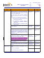
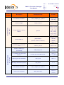
Table 15: Calibrated visibilities breakpoint file
Name
Size
Line format
Separator
Comment
calibvis_****.txt
72 x 144
floats
144 floats
Blank
space
The file contains a representation of
the 72x72 matrix with the calibrated
visibilities. Odd columns have the real
part, even columns have the imaginary
part.
Please note that the file format is different between complex correlations, where real and imaginary
parts are separated in different files, and for the other breakpoints with complex data, where the real and
imaginary parts are separated by columns.
For the case of Correlated Noise Injection epochs, only the first 3 type of breakpoints will be generated,
using the “cnoise” prefix and the OBET suffix rather than the snapshot ID which is only meaningful for
science data.
For the case of Uncorrelated Noise Injection epochs, only the 4th and 6th type of breakpoints will be
generated, using the “unoise” prefix, but in this case the snapshot ID is used. The ordering inside are
two columns of data, the first column is the real part and the second column is the imaginary part, and
the number of lines is 72x72.
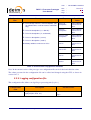
5.2.4.2. L1B and Foreign Sources Breakpoints
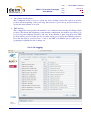
Foreign Sources breakpoints are activated in the L1PP configuration file, or through the L1PP User
Interface by activating the flags "Print FS Breakpoints" and "Print FS Extra Breakpoints". If any of
these flags is set, a set of breakpoint files will be created in the directory $L1PP_ROOT/breakpoint.
L1b Scenes breakpoints are activated in the L1PP configuration file, or through the L1PP User Interface
by activating the flags "Print L1B Scenes" and “Print L1B Scenes BT” respectively. If any flag is set a
breakpoint will be generated per scene, with the (u,v) baselines or (xi,eta) coordinates and the
corresponding real and imaginary parts of the Fourier components of the brightness temperature in the
antenna frame, or the brightness temperatures themselves obtained through a FFT
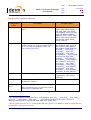
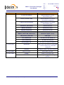
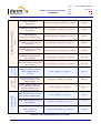
The following table shows, in the third column, the breakpoint names implemented in the Image
Reconstruction Module of the current L1b baseline.
The first column indicates the location in the L1PP implementation where the breakpoint is taken (see
the diagram of Figure 3 in [RD.6]), and the common prefix in the breakpoints filenames.
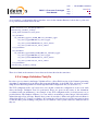
This document is property of DEIMOS Engenharia and cannot be distributed or duplicated without its written permission.