1
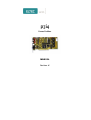
p3i4
Frame Grabber
manual
Revision 1E
Revision
Revision Changes
Date / Name
1A
First Edition, valid for Hardware revision 1A,
2A
15.05.98 cw
1B
valid for Hardware revision 2x
07.10.98 cw
1C
valid for Hardware revision 2x
12.12.00 dp
1D
valid for Hardware revision 2x
25.06.01 cw
1E
Disclaimer new
08.11.06 hh
DISCLAIMER
Copyright
© 2006 ELTEC Elektronik AG. The information, data, and figures in this
document including respective references have been verified and
found to be legitimate. In particular in the event of error they may,
therefore, be changed at any time without prior notice. The complete
risk inherent in the utilization of this document or in the results of its
utilization shall be with the user; to this end, ELTEC Elektronik AG shall
not accept any liability. Regardless of the applicability of respective
copyrights, no portion of this document shall be copied, forwarded or
stored in a data reception system or entered into such systems without
the express prior written consent of ELTEC Elektronik AG, regardless of
how such acts are performed and what system is used (electronic,
mechanic, photocopying, recording, etc.). All product and company
names are registered trademarks of the respective companies.
Our General Business, Delivery, Offer, and Payment Terms and
Conditions shall otherwise apply.
Federal communications commission statement
Þ This device complies with FCC Rules Part 15. Operation is subject
to the following two conditions:
Þ This device may not cause harmful interference, and
Þ This device must accept any interference received including
interference that may cause undesired operation.
Þ This equipment has been tested and found to comply with the
limits for a Class B digital device, pursuant to Part 15 of the FCC
Rules. These limits are designed to provide reasonable protection
against harmful interference in a residential installation. This
equipment generates, uses and can radiate radio frequency
energy and, if not installed and used in accordance with
Þ
Þ
Þ
Þ
Þ
manufacturer’s instructions, may cause harmful interference to
radio communications. However, there is no guarantee that
interference will not occur in a particular installation. If this
equipment does cause harmful interference to radio or television
reception, which can be determined by turning the equipment off
and on, the user is encouraged to try correct the interference by
one or more of the following measures:
Reorient or relocate the receiving antenna.
Increase the separation between the equipment and receiver.
Connect the equipment to an outlet on a circuit different from
that to which the receiver is connected.
Consult the dealer or an experienced radio/TV technician for help.
The us of shielded cables for connection of the monitor to the
graphics card is required to assure compliance with FCC
regulations. Changes or modifications to this unit not expressly
approved by the party responsible for compliance could void the
user’s authority to operate this equipment.
Canadian department of communications statement
Þ This digital apparatus does not exceed the Class B limits for radio
noise emissions from digital apparatus set out in the Radio
Interference Regulations of the Canadian Department of
Communications.
Þ This class B digital apparatus complies with Canadian ICES-003
SAFETY INFORMATION
Electrical safety
Þ To prevent electrical shock hazard, disconnect the power cable
from the electrical outlet before reloading the system.
Þ When adding or removing devices to or from the system, ensure
that the power cables for the devices are unplugged before the
signal cables are connected. If possible, disconnect all power
cables from the existing system before you add device.
Þ Before connecting or removing signals cables from motherboard,
ensure that all power cables are unplugged.
Þ Make sure that your power supply is set to the correct voltage in
your area. If you are not sure about the voltage of the electrical
outlet you are using, contact your local power company.
Þ If the power supply is broken, do not try to fix it by yourself.
Contact a qualified service technician or your retailer.
Operation safety
Þ Before installing the motherboard and adding devices on it,
carefully read the manuals that came with the package.
Þ Before using the product, make sure all cables are correctly
connected and the power cables are not damaged. If you detect
any damage, contact your dealer immediately.
Þ To avoid short circuits, keep paper clips, screws, and staples away
from connectors, slots sockets and circuitry.
Þ Avoid dust, humidity, and temperature extremes. Do not place the
product in any area where it may become wet.
Þ Place the product on a stable surface.
Þ If you encounter technical problems with the product, contact a
qualified service technician or your retailer.
EMC Rules
This unit has to be installed in a shielded housing. If not installed in a
properly shielded enclosure, and used in accordance with the
instruction manual, this product may cause radio interference in which
case the user may be required to take adequate measures at his or her
own expense.
IMPROTANT INFORMATION
This product is not an end user product. It was developed and
manufactured for further processing by trained personnel.
RECYCLING
Please recycle packaging environmentally friendly:
Packaging materials are recyclable. Please do not dispose
packaging into domestic waste but recycle it.
Please recycle old or redundant devices environmentally
friendly:
Old devices contain valuable recyclable materials that should
be reutilized. Therefore please dispose old devices at collection points
which are suitable.
User’s Manual
Table of Contents
Table of Contents
1
Installation .............................................................................1—1
1.1 Packing List ........................................................................1—1
1.2 Installation Requirements ...................................................1—2
1.3 Hardware Installation ..........................................................1—3
1.4 Hardware Documentation ...................................................1—4
2
Quick Start.............................................................................2—1
2.1 For a (CCIR) Monochrome Camera ...................................2—1
2.2 For a Color (SVHS) Camera...............................................2—5
3
Specification ..........................................................................3—1
3.1 Understanding the Grabber - How the
®
PC_EYE 4 Works - ............................................................3—1
3.1.2 Color Block Data Flow.................................................3—2
3.1.3 Monochrome Block Data Flow ....................................3—3
3.2 Have no fear of Jumpers! - Configuring the
®
PC_EYE 4 for your Camera -.............................................3—6
3.3 Enhancements on Boards with Layout
Revisions 3 or Greater.......................................................3—17
3.4 Improved Driver Capacilities.............................................3—17
PC_EYE®4
I
Table of Contents
User’s Manual
List of Tables
Table 1: SVHS Connector X604 ...................................................3—2
Table 2: MIN-D Connector X603...................................................3—3
Table 3: Feature Connector X606.................................................3—5
Table 4: HIROSE pin 6 Jumpering..............................................3—10
Table 5: HIROSE pin 7 Jumpering..............................................3—11
Table 6: HIROSE pin 9 Jumpering..............................................3—13
Table 7: HIROSE pin 11 Jumpering............................................3—14
II
PC_EYE®4
User’s Manual
Table of Contents
List of Figures
Figure 1: Main Window .................................................................2—2
Figure 2: Global Parameters.........................................................2—3
Figure 3: Input Selection ...............................................................2—3
Figure 4: Packing Mode ................................................................2—4
Figure 5: SVHS Camera Selection ...............................................2—6
Figure 6: SVHS Input Selection ....................................................2—7
Figure 7: Color Packing Mode ......................................................2—8
®
Figure 8: Block Diagram PC_EYE 4 ............................................3—1
Figure 9: SVHS Connector X604 ..................................................3—2
Figure 10: MIN-D Connector X603 ...............................................3—3
Figure 11: Feature Connector X606 .............................................3—5
Figure 12: Camera Power Supply Connections............................3—7
Figure 13: Video Signal Connections............................................3—8
Figure 14: External Pixel Clock Connections..............................3—12
Figure 15: Jumper and Connector Locations..............................3—15
PC_EYE®4
III
Table of Contents
IV
User’s Manual
PC_EYE®4
Installation
1 Installation
For complete instructions see the Help File - see software installation
section on how to install the Help System.
1.1 Packing List
Please compare the components with the following packing list:
Caution! Prevent static electrical damage. Static charges can cause severe
damage to microcircuits.
®
1 PC_EYE 4 Framegrabber board
Order numbers: V-PCEY-400x (full version)
V-PCEY-410x (single monochrome channel)
V-PCEY-420x (S-video only)
1 Configuration jumper package
If there are any of these items missing, contact your ELTEC dealer.
PC_EYE®4
1—1
Installation
User’s Manual
Installation
User’s Manual
Installation
1.2 Installation Requ irements
PC/Operating system:
PC with Windows 98, ME, NT, 2000 operating system.
Harddisk:
At least 10 MB free space.
PCI bus:
Compliant with PCI specification 2.0 or higher with transfer rate PCI-tomemory >= 30 MB/s.
Graphics:
PCI-based graphics board with 24-bits-per-pixel mode for optimum speed.
16-bit-per-pixel HiColor and 32-bit true-color modes are also supported.
PCI BIOS:
Compliant with PCI specification 2.0 or higher.
Interrupts/DMA:
No interrupts needed by current software. Busmaster DMA transfers used.
Software:
®
PC_EYE 4 Basic Tools for driver DLL, test and installation.
1—2
PC_EYE®4
Installation
1.3 Hardware Install ation
•
Depending on the type of the grabber and the operation system used,
the software has to be installed before or after the hardware. Refer to
the driver installation guide to find which comonent has to be
installed first.
•
Switch off computer. Prepare workspace to observe electrostatic
discharge (ESD) precautions before opening computer or removing the
®
PC_EYE 4 from its case: Touch computer steel case during
®
insertion/removal of the PC_EYE 4 or take other precautions to ensure
the absence of high voltages due to electric charges.
•
Open computer case, remove blind back panel.
•
Insert the PC_EYE 4 into free PCI slot. The board must fit into the
slot without use of excessive force, make sure it sits firmly in the slot.
•
Fix PC_EYE 4 back panel with screw, connect camera, close
computer case.
®
®
Caution! The connector X603 has the same mechanical appearance as an
VGA video output connector. It should not be confused with the latter!
To avoid damage to the hardware do not connect a VGA monitor to X603!
Caution! On pin 15 of X603 either 5V or 12V are delivered to power the
video camera. The current that can be drawn from this pin is limited with a
PTC resistor (Imax ca. 500 mA). Be sure not interchange 12V- and 5Voutputs!
PC_EYE®4
1—3
Installation
User’s Manual
Installation
User’s Manual
Installation
1.4 Hardware Docum entation
The hardware documentation is provided as PDF file.
To see which cameras are supported please have a look at the camera
documentation.
1—4
PC_EYE®4
User’s Manual
Quick Start
2 Quick Start
®
2.1 For a (CCIR) Mon ochrome Camera
®
Connect your camera to the PC_EYE 4’s monochrome channel 1, that is the
circular connector at the top of the backpanel (HIROSE 1). You should use
a standard 12-pin video cable, available from your local video equipment
provider or directly from ELTEC.
Make sure that a floppy-type connector from your PC’s power unit is
®
plugged into X607 on the PC_EYE 4’s right side. This will ensure that your
camera is powered directly from your PC without need for an external
power unit. Consult your camera manual how to select a free running mode.
®
Normally this is the factory setting. On the PC_EYE 4 no further jumper
setting is necessary. Assumed you have installed the configuration software,
®
®
start ’PC_EYE 4 Configuration’ from the ’PC_EYE 4 Basic Tools’ menu.
®
The program will scan the PCI-Bus for installed PC_EYE 4 boards.
All boards found will be shown in the main window (see Figure 1). Select
one of them by clicking on it. This will open an acquisition window. Click
on the ’pocket-knife-button’. The ’Configuration’ menu comes up. Activate
the ’Camera’ register card to select the global parameters (see Figure 2).
Notice that the ’Frame Size (Pixel)’ area on the right is related to the image
buffer in memory and the acquisition window size on your desktop, not to
the actual sensor dimensions of the camera. So there is no need to adapt the
slider settings exactly to the sensor dimensions.
Now activate the register card ’Input’. The right choice here is ’BW Input 0’
(Figure 3). The last selection which has to be made is ’8-bit monochrome’ in
register card ’Packing mode’ (Figure 4). This means that the digitized image
data will be placed into the acquisition buffer in the form one byte per pixel.
Close the configuration menu by clicking the ’OK’-button. Now the grabber
PC_EYE®4
2—1
Quick Start
To quickly test functionality of the PC_EYE 4 only a few steps have to be
done.
Quick Start
User’s Manual
is ready to acquire the first image. Press the ’pocket-camera button’ to
snapshot a single image or the ’film-camera button’ for continuous
acquisition.
Quick Start
Figure 1: Main Window
2—2
PC_EYE®4
Quick Start
Quick Start
User’s Manual
Figure 2: Global Parameters
Figure 3: Input Selection
PC_EYE®4
2—3
Quick Start
User’s Manual
Quick Start
Figure 4: Packing Mode
2—4
PC_EYE®4
User’s Manual
Quick Start
2.2 For a Color (SVH S) Camera
All boards found will be indicated in the main window (see Figure 1).
Select one of these by clicking on it. This will open an acquisition window.
Click on the ’pocket-knife-button’. The ’Configuration’ menu comes up.
Activate the ’Camera’ register card to select the global parameters (see
Figure 5). Notice that the ’Frame Size (Pixel)’ area on the right is related to
the image buffer in memory and the acquisition window size on your
desktop, not to the actual sensor dimensions of the camera.
So there is no need to adapt the slider settings exactly to the sensor
dimensions. From the camera select box choose ’Generic PAL (YC/CVBS)’.
Activate the register card ’Input’. Choose ’SVHS Input 0’ (Figure 6). Now
click on register card ’Packing Mode’. For this example select the check box
’16-bit packed RGB (5-6-5) (Figure 7). Each pixel will be stored in two
bytes containing five bits for the red and the blue component and six bits for
the green component of the image data. Close the configuration menu by
clicking the ’OK’-button. Now the grabber is ready to acquire the first
image. Press the ’pocket-camera button’ to snapshot a single image or the
’film-camera button’ for continuous acquisition.
PC_EYE®4
2—5
Quick Start
®
Connect your camera to the PC_EYE 4’s SVHS input connector (X604). It
is located above the MIN-D connector in the backpanel’s middle. You
should use a standard 4-pin s-video cable, which is available from your
local video equipment provider or directly from ELTEC. Ensure that your
camera is powered by its external power unit. Assumed you have installed
®
the configuration software, start ’PC_EYE 4 Configuration’ from the
®
’PC_EYE 4 Basic Tools’ menu. The program will scan the PCI-Bus for
®
installed PC_EYE 4 boards.
Quick Start
User’s Manual
Quick Start
Figure 5: SVHS Camera Selection
2—6
PC_EYE®4
Quick Start
Quick Start
User’s Manual
Figure 6: SVHS Input Selection
PC_EYE®4
2—7
Quick Start
User’s Manual
Quick Start
Figure 7: Color Packing Mode
2—8
PC_EYE®4
User’s Manual
Specification
3 Specification
3.1 Understanding th e Grabber
- How the PC_EYE®4 Works ®
Figure 10 shows the main building blocks of the PC_EYE 4. Basically the
board consists of two parts: one for standard color video sources and
another for monochrome video. Especially the monochrome part can be
adapted in a flexible manner to work with a variety of cameras.
ADC1
Video1
LUT1
PCI-DMA
MUX
MUX
PCI-Bus
SAA7146
LUT2
ADC2
HIROSE1
Video2
Digital I/O
MIN-D
Video1
Video2
Y2
C2
SVHS
Y1
Color
Video
C1
Decoder
®
Figure 8: Block Diagram PC_EYE 4
PC_EYE®4
3—1
Specification
HIROSE2
Specification
User’s Manual
3.1.2 Color Block Data Flo w
®
With its video decoder (SAA7111) the PC_EYE 4 is able to digitize and
process standard analog color video sources. On its back panel input X604
one SVHS signal (Y1, C1) or two CVBS signals (CVBS3, CVBS4) may be
connected. Also the MIN-D input X603 may serve as source of the same
type of signals (Y2/CVBS3, C2/CVBS4) on its pins 3 and 4, (see figure 9
and 10). However, after selecting one of these sources the video decoder
allows only one signal at a time to be processed. After digitization the
image data is transferred to the PCI DMA controller (SAA 7146). The
DMA controller is capable of resizing the image data and transfer it to the
main memory or graphics card using different formats such as RGB32, 24,
16, 15-bit, YUV4:2:2, 4:4:4 (24-bit/pixel), or monochrome 8-bit.
Specification
Front View
Pin2
Pin1
Pin4
Pin3
SHELL
Figure 9: SVHS Connector X604
Table 1: SVHS Connector X604
Pin
1
2
3
4
Shell
3—2
Function
Y1/CVBS1
C1/CVBS2
GND
GND
SHIELD
PC_EYE®4
User’s Manual
Specification
Front view
Pin5
Pin1
Pin10
Pin6
Pin15
Pin11
Figure 10: MIN-D Connector X603
Table 2: MIN-D Connector X603
Signal
BW_VIDEO1
BW_VIDEO2
Y2/CVBS3
4
C2/CVBS4
5
6
7
8
9
10
11
12
13
14
GND
GND
GND
GND
TRIG_IN+
GND
TRIG_INPIXCLK_IN
HSYNC_OUT
(dual purpose)
15
POWER1
Function
analog input for monochrome cameras channel1
analog input for monochrome cameras channel2
channel2 analog input color cameras (Y from SVHS or
CVBS3 from FBAS)
channel2 analog input color cameras (C from SVHS or
CVBS4 from FBAS)
Specification
Pin
1
2
3
user defined input to opto-coupler
user defined input to opto-coupler
external pixel clock input
horizontal sync output (TTL)
composide sync output (TTL) / camera control output
(TTL) (dependent on J612 setting)
power output +12V/+5V (dependent on J611 setting)
3.1.3 Monochrome Block Data Flow
®
The PC_EYE 4’s monochrome block provides for two acquisition channels
capable of acquiring images from two synchronized cameras in parallel
(stereo mode). If not synchronized, only one camera at a time can be used
for acquisition. As in the color block the MIN-D connector X603 as well as
the HIROSE™ inputs may be used as source of max. two different video
signals.
Caution! Don’t use the same video line on the MIN-D connector and on
one of the two HIROSEs in order not to mix different signals. (For proper
PC_EYE®4
3—3
Specification
User’s Manual
use of the inputs and configuration jumpers see chapter ‘No fear of
jumpers!’).
The video signals are digitized by two AD converters of type HI1179 with
8-bit/pixel resolution and a maximum pixel clock frequency of 30 MHz. At
this point the digital data is routed to connector X605, where it is always
available, except the case connector X605 is configured to be digital input.
In the latter case the AD converter’s outputs are disabled in order not to
interfere with the digital input data.
The digital I/O connector X605 is reserved for future use. So don’t
connect a digital camera or other hardware to it! Contact ELTEC if
you intend to utilize this port in the future.
Specification
Independent of its source the digital data of each channel passes a
programmable 8-bit look-up-table before it is presented to the PC-DMA
controller.
Additional features
The feature connector X606 provides for all five camera control signals
which must be programmed appropriate to become meaningful. Also the
user definable trigger inputs to the opto-coupler as well as the I2C-Bus
signals are available (see figure 11).
3—4
PC_EYE®4
User’s Manual
Specification
Pin16
Pin2
View from top
Pin16
Pin1
Figure 11: Feature Connector X606
Table 3: Feature Connector X606
Signal
CAM_CTRL0
CAM_CTRL1
CAM_CTRL2
CAM_CTRL3
CAM_CTRL4
NC
NC
GND
GND
GND
TRIG_IN+
TRIG_INGND
GND
SCL
SDA
Function
camera control output 0
camera control output 1
camera control output 2
camera control output 3
camera control output 4
Specification
Pin
1
2
3
4
5
6
7
8
9
10
11
12
13
14
15
16
user defined input to opto-coupler
user defined input to opto-coupler
I2C-Bus clock signal
I2C-Bus data signal
®
If you intend to supply power to your camera from the PC_EYE 4 the
floppy type connector X607 comes into play. This connector routes the
PC’s 12 Volt power directly (but fused) to both HIROSE connectors pin 2.
This connection is fixed and cannot be changed. Use X607 the same way as
you do with e.g. a hard disk drive’s power connector. If your camera
requires 12 Volt applied to another pin this can be achieved by setting the
camera configuration jumpers accordingly (see next chapter). The same
voltage is applied to the MIN-D connector X603, pin 15 if jumper J611 is
set towards the board edge.
PC_EYE®4
3—5
Specification
User’s Manual
3.2 Have no fear of J umpers!
- Configuring the PC_EYE®4 for
your Camera ®
Specification
With its camera configuration jumpers the PC_EYE 4 provides an effective
method of adapting your favorite camera to run on this grabber using the
standard HIROSE‰ video cable. In most cases however to capture images
from a camera in free running mode requires no jumper setting at all. For a
quick start it will be sufficient to apply the analog video signal to HIROSE
pin 4 or MIN-D pin 13. If you intend to run your camera in a more
®
specialized manner, e.g. in restart mode or synchronized by the PC_EYE 4,
you should have no fear of setting the camera configuration jumpers
according to your needs. It must be said, however, that it is absolutely
necessary to understand what you are doing in order not to damage your
camera. This chapter provides information on how to set these jumpers
correctly in conjunction with cameras not yet supported by ELTEC.
In general, the configuration jumpers are labeled as follows. On the left side
you will find in short form the HIROSE connector and the pin the jumper is
connected to. For example the label
H2_11
means: This jumper is routed to pin 11 of HIROSE connector No. 2. On the
right side you will find a short form of an elementary grabber signal line.
Example: H2_7
PCLK
Setting this jumper will connect pin 7 of HIROSE connector 2 to the
external pixel clock line. If more than one choice is available for the same
HIROSE pin you will find a group of jumpers with only one label on the
left. This means all these jumpers connect to the same HIROSE pin.
Therefore in such a group it is not allowed to set more than one jumper.
The two HIROSE connectors on the PCI backpanel correspond to the two
®
AD channels on the PC_EYE 4. In detail the connections are as follows:
3—6
PC_EYE®4
User’s Manual
Specification
PIN 1: GND (not changeable)
PIN 2: POWER2
POWER2 means this pin may be connected to the host PC’s power supply i.
e. +12 Volts. Nearly all cameras derive its power from this pin. The
®
PC_EYE 4 provides for a connection from X607 (that is the floppy type
connector on the inner side of the board) to the HIROSE’s pin 2. Therefore
if you connect X607, (as you do e.g. with a floppy or a CD-ROM drive),
+12 Volts are applied to the HIROSE’s so that your camera is powered
directly from your PC. See figure 12:
HIROSE1
11
Specification
2
+12V
H111
(Floppytype
Connector)
HIROSE2
2
11
+12V
H211
15pin MIN-D
+5V
15
J611
Figure 12: Camera Power Supply Connections
The voltage applied to pin 15 of the MIN-D connector depends on the
jumper setting J611. Set jumper J611 towards the board edge to apply
PC_EYE®4
3—7
Specification
User’s Manual
+12 Volts to the MIN-D pin 15. Set J611 towards C601 to apply +5 Volts to
MIN-D pin 15.
PIN 3: GND (not changeable)
PIN 4: Analog video input to channel 1 and channel 2.
HIROSE1
4BW_video1
ADC1
9
H1_9
VID2
Specification
HIROSE2
MUX
4BW_video2
15pin MIN-D
1BW_video1
2BW_video2
Figure 13: Video Signal Connections
3—8
ADC2
PC_EYE®4
User’s Manual
Specification
Figure 6 shows how to connect analog video signals to the input multiplexer
which links software selectable both inputs to both AD converters. You may
use video input on the HIROSE’s and alternatively on the MIN-D, pin 1 and
2, but not both in order not to mix different video sources. As you can see in
figure 6 pin 7 of HIROSE connector 1 may be connected to video line 2 by
setting the configuration jumper labeled HIROSE1_9 (H1_9) on the left
and BW_video2 (VID2) on the right. By means of this cameras which
provide a dual video on its pins 4 and 9 i. e. separate even and odd fields
can be used. The fields are digitized in parallel. In this case only one camera
can be used and HIROSE connector 2 must be left unconnected.
Pin 5 of each HIROSE connector may be connected to ground or may be
left open. In many cases pin 5 connects to the inner shield of conductor on
pin 6.
6HW MXPSHU ODEHOHG +B RQ WKH OHIW VLGH DQG *1' RQ WKH ULJKW VLGH
to connect pin 5 of HIROSE1 to ground potential.
6HW MXPSHU ODEHOHG +B RQ WKH OHIW VLGH DQG *1' RQ WKH ULJKW VLGH
to connect pin 5 of HIROSE2 to ground potential
PIN 6: multiple purpose pin
For pin 6 of each HIROSE connector you have three choices. See table 4:
PC_EYE®4
3—9
Specification
PIN 5: multiple purpose pin
Specification
User’s Manual
Table 4: HIROSE pin 6 Jumpering
Specification
left label
H1_6
right label
CTR0
H1_6
CTR1
H1_6
HSYN
H2_6
CTR0
H2_6
CTR1
H2_6
HSYN
does the following
Connects pin 6 of HIROSE connector 1 to the CAM_CONTROL0
output, which is normally used for restart purposes. The PC_EYE®4
must be programmed appropriately to generate e. g. a restart signal
on this line.
Connects pin 6 of HIROSE connector 1 to the CAM_CONTROL1
output, which can be used for different control purposes. The
PC_EYE®4 must be programmed appropriately to generate a
meaningful signal on this line.
Connects pin 6 of HIROSE connector 1 to the HSYNC output of the
PC_EYE®4’s sync generator. By means of this a camera can be
horizontally synchronized by the grabber. When acquiring pictures
from two cameras in parallel (stereo mode) synchronizing is
generally necessary, because the AD channels cannot be run
asynchronously to each other. The PC_EYE®4 must be
programmed appropriately to generate the correct HSYNC-timing.
Connects pin 6 of HIROSE connector 2 to the CAM_CONTROL0
output, see H1_6 - CTR0 above.
Connects pin 6 of HIROSE connector 2 to the CAM_CONTROL1
output, which can be used for different control purposes, see H1_6 CTR1 above.
Connects pin 6 of HIROSE connector 2 to the HSYNC output of the
PC_EYE®4’s sync generator, see H1_6 - HSYN above.
Caution! Don’t set any of the jumpers H1_6 and H2_6 if you are not sure
whether your camera drives some sort of output on its HIROSE pin 6. This
will probably damage camera and/or grabber.
PIN 7: multiple purpose pin
You may chose one of three alternatives for pin 7 of each HIROSE
connector. See table 2:
3—10
PC_EYE®4
User’s Manual
Specification
left label
H1_7
right label
CTR0
H1_7
CVSY
H1_7
PCLK
H2_7
CTR0
H2_7
CVSY
H2_7
PCLK
does the following
Connects pin 7 of HIROSE connector 1 to the CAM_CONTROL0
output, which is used for restart purposes very often. The
PC_EYE®4 must be programmed appropriately to generate e. g. a
restart signal on this line.
Connects pin 7 of HIROSE connector 1 to the CVSYNC output of
the PC_EYE®4’s sync generator. ‘CV’ means this output can be
programmed to be either a composite sync (vertical and horizontal
sync enclosed in one signal) or a pure vertical sync only. By means
of this a camera can be vertically synchronized by the grabber.
When acquiring pictures from two cameras in parallel (stereo mode)
synchronizing is generally necessary, because the AD - channels
cannot be run asynchronously to each other. The PC_EYE®4 must
be programmed appropriately to generate the correct CSYNC timing.
Connects pin 7 of HIROSE connector 1 to the external pixelclock
input of the PC_EYE‚4. By this the camera determines the sampling
point of each pixel in the analog video signal. Make sure not to
exceed a maximum frequency of 30 MHz for the external pixelclock.
Caution! Only one of the two HIROSEs or the MIN-D connector
may serve as source for this clock. When setting this jumper don’t
set jumper H2_7 - PCLK, because this will mix different clock
signals! The use of the external clock must be switched on by the
configuration software to become effective.
Connects pin 7 of HIROSE connector 2 to the CAM_CONTROL0
output, see H1_7 - CTR0 above.
Connects pin 7 of HIROSE connector 2 to the CVSYNC output of
the PC_EYE®4’s sync generator, see H1_7 - HSYN above.
Connects pin 7 of HIROSE connector 2 to the external pixelclock
input of the PC_EYE®4, see H1-7 - PCLK above.
Caution! Only one of the two HIROSEs or the MIN-D connector
may serve as source for this clock. When setting this jumper don’t
set jumper H1_7 - PCLK, because this will mix different clock
signals!
Caution! Don’t set any of the jumpers H1_7 - CTR0, H1_7 - CVSY,
H2_7 - CTR0 and H2_7 - CVSY if you are not sure whether your camera
drives some sort of output on its HIROSE pin 7. This will probably damage
camera and/or grabber.
Figure 7 shows the connections of the external pixel clock. Make sure to use
only one source for this signal.
PC_EYE®4
3—11
Specification
Table 5: HIROSE pin 7 Jumpering
Specification
User’s Manual
HIROSE1
7
H1-7
PCLK
9
H1-7
HIROSE2
PCLK
Clock
Regeneration
H2-7
PCLK
7
9
H2-9
PCLK
Specification
15pin MIN-D
13
Figure 14: External Pixel Clock Connections
PIN 8: multiple purpose pin
Pin 8 of each HIROSE connector may be connected to ground or may be
left open. In many cases pin 8 connects to the inner shield of conductor on
pin 7.
6HW MXPSHU ODEHOHG +B RQ WKH OHIW VLGH DQG *1' RQ WKH ULJKW VLGH
to connect pin 8 of HIROSE1 to ground potential.
6HW MXPSHU ODEHOHG +B RQ WKH OHIW VLGH DQG *1' RQ WKH ULJKW VLGH
to connect pin 8 of HIROSE2 to ground potential
3—12
PC_EYE®4
User’s Manual
Specification
PIN 9: multiple purpose pin
Most options are available for pin 9 of each HIROSE connector. See also
figure 13 and figure 14. See table 6:
left label
H1_9
right label
CTR0
H1_9
CTR1
H1_9
HSYN
H1_9
PCLK
H2_9
CTR0
H2_9
CTR1
H2_9
HSYN
H2_9
PCLK
does the following
Connects pin 9 of HIROSE connector 1 to the CAM_CONTROL0
output, which is used for restart purposes very often. The PC_EYE®4
must be programmed appropriately to generate e. g. a restart signal
on this line.
Connects pin 9 of HIROSE connector 1 to the CAM_CONTROL1
output, which can be used for different control purposes. The
PC_EYE®4 must be programmed appropriately to generate a
meaningful signal on this line.
Connects pin 9 of HIROSE connector 1 to the HSYNC output of the
PC_EYE®4’s sync generator. By means of this a camera can be
horizontally synchronized by the grabber. When acquiring pictures
from two cameras in parallel (stereo mode) synchronizing is generally
necessary, because the AD - channels cannot be run asynchronously
to each other. The PC_EYE®4 must be programmed appropriately to
generate the correct HSYNC - timing.
Connects pin 9 of HIROSE connector 1 to the external pixel clock input
of the PC_EYE®4, see H1_7 - PCLK above. Caution! Only one of the
two HIROSEs or the MIN-D connector may serve as source for this
clock. When setting this jumper don’t set jumper H2_9 - PCLK,
because this will mix different clock signals!
Connects pin 9 of HIROSE connector 2 to the CAM_CONTROL0
output, see H1_9 - CTR0 above.
Connects pin 9 of HIROSE connector 2 to the CAM_CONTROL1
output, which can be used for different control purposes, see H1_9 CTR1 above.
Connects pin 9 of HIROSE connector 2 to the HSYNC output of the
PC_EYE®4’s sync generator, see H1_9 - HSYN above.
Connects pin 9 of HIROSE connector 2 to the external pixelclock input
of the PC_EYE®4, see H1_9 - PCLK above. Caution! Only one of the
serve as source for this clock. When setting this jumper don’t set
jumper H1_9 - PCLK, because this will mix different clock signals!
Caution! Don’t set any of the jumpers H1_9 - CTR0, H1_9 - CTR1,
H1_9 - HSYN,
H2_9 - CTR0, H2_9 - CTR1 and H2_9 - HSYN if you are not sure whether
your camera drives some sort of output on its HIROSE pin 9. This will
probably damage camera and/or grabber.
PC_EYE®4
3—13
Specification
Table 6: HIROSE pin 9 Jumpering
Specification
User’s Manual
PIN 10: multiple purpose pin
Pin 10 of each HIROSE connector may be connected to ground or may be
left open. In many cases pin 10 connects to the inner shield of conductor on
pin 9.
6HW MXPSHU ODEHOHG + RQ WKH OHIW VLGH DQG *1' RQ WKH ULJKW VLGH
connect
pin
10
of
HIROSE1
to
ground
potential.
6HW MXPSHU ODEHOHG + RQ WKH OHIW VLGH DQG *1' RQ WKH ULJKW VLGH
to connect pin 10 of HIROSE2 to ground potential
to
PIN 11: multiple purpose pin
Specification
You may chose one of three alternatives for pin 11 of each HIROSE
connector. See table 7:
Table 7: HIROSE pin 11 Jumpering
left label
H111
right label
+12V
H111
CTR1
H111
CTR0
H211
+12V
H211
CTR0
H211
CTR1
does the following
Connects pin 11 of HIROSE connector 1 to the +12 Volt Power X607,
see figure 14 and PIN 2. Some cameras derive their 12Volt power
from HIROSE pin 11. Setting this jumper will allow this.
Connects pin 11 of HIROSE connector 1 to the CAM_CONTROL1
output, which can be used for different control purposes. The
PC_EYE®4 must be programmed appropriately to generate a
meaningful signal on this line.
Connects pin 11 of HIROSE connector 1 to the CAM_CONTROL0
output, which is used for restart purposes very often. The PC_EYE®4
must be programmed appropriately to generate e. g. a restart signal on
this line.
Connects pin 11 of HIROSE connector 2 to the +12 Volt Power X607,
see figure 14 and PIN 2. Some cameras derive its 12 Volt power from
HIROSE pin 11. Setting this jumper can accomplish this.
Connects pin 11 of HIROSE connector 2 to the CAM_CONTROL0
output, see H111 - CTR0 above.
Connects pin 11 of HIROSE connector 2 to the CAM_CONTROL1
output, see H111 - CTR1 above.
Caution! Don’t set any of the jumpers H111 and H211 if you are not sure
whether your camera drives some sort of output on its HIROSE pin 11. This
will probably damage camera and/or grabber.
PIN 12: multiple purpose pin
3—14
PC_EYE®4
User’s Manual
Specification
Pin 12 of each HIROSE connector may be connected to ground or may be
left open. In many cases pin 12 connects to the inner shield of conductor on
pin 11.
Set jumper labeled H112 on the left side and GND on the right side
to connect pin 12 of HIROSE1 to
ground
potential.
Set jumper labeled H212 on the left side and GND on the right side
to connect pin 12 of HIROSE2 to ground potential.
Other Settings
Feature connector
X606
Specification
Figure 15 illustrates all important jumper and connector locations. There are
a few more jumpers with special purposes:
EPROM write enable
J103
Camera configuration
jumpers
J102
HIROSE1
J101
Board identification
jumpers
HIROSE1
X607
Power
connector
HIROSE2
HIROSE2
X605
Digital
Input/Output
Only for ELTEC use
X604 SVHS-Input
HIGH
LOW
X603 MIN-D Connector
H2
C2
H1
C1
J612
Function select for
MIN-D Pin 14
HIGH
J611
MIN-D Power
select
Detail
LOW
only on Rev.3 or greater
Figure 15: Jumper and Connector Locations
PC_EYE®4
3—15
Specification
User’s Manual
J611 was already mentioned before (see pin 2). It determines the voltage
applied to pin 15 of the MIN-D connector. Set jumper J611 towards the
board edge to apply +12 Volts to the MIN-D pin 15. Set J611 towards C601
to apply +5Volts to MIN-D pin 15.
J612 selects the output signal which is applied to pin 14 of the MIN-D
connector. Set J612 towards the board edge to connect the
CAM_CONTROL0 output to MIN-D pin 14. Setting J612 towards U304
®
connects the CVSYNC output from the PC_EYE 4’s sync generator to
MIN-D pin 14.
Specification
J101, J102 (upper right) are used to identify each board in the case that
more than one grabber is used on the same PCI-Bus. With these jumpers set
differently on multiple boards the software is able to differ exactly between
them. Up to four combinations of these jumpers allow using the same
number of boards in parallel on one PCI-Bus.
J103 is used to enable the user portion of the onboard EPROM for writing.
This jumper must be set if you intend to change the contents of the
EPROM. Reading the memory is always possible.
3—16
PC_EYE®4
User’s Manual
Specification
3.3 Enhancements on Boards with
Layout Revisions 3 or Greater
For example ’H2’ refers to HSYNC output for channel 2, ’C1’ refers to
composite sync output for channel 1.
3.4 Improved Driver Capabilities
Some cameras use very strong dimensionated termination resistors at their
sync-input lines. Since PC_EYE®4 boards up to layout revision 2 have a
single driver for both camera sync outputs these signals may collapse in
some cases. The work-around was to use only cameras with termination
resistors which can be turned off.
Revision 3-boards (or greater) avoid the described problem by driving each
sync-output with its own driver.
PC_EYE®4
3—17
Specification
PC_EYE®4 boards with layout versions greater 3 (Rev.D) feature additional
jumpers labelled ’H2’, ’C2’, ’H1’, ’C1’, which allow for adjusting the output
sync signal level. The default setting (delivery) is all set to ’HIGH’, which
means that the sync signal output level is TTL, i.e. ca. 4.2 V high-level.
However some cameras expect video-like external sync levels. In this case
each sync signal may be set individually to an output high level of 0.7 V,
(’LOW’).
Specification
User’s Manual
Specification
3—18
PC_EYE®4
ELTEC Elektronik AG
Galileo-Galilei-Str. 11
Phone: +49 (0) 6131 918-520
FAX: +49 (0) 6131 918-196
D-55129 Mainz
email: [email protected]
TECHNICAL ACTION REQUEST
Customer Name: ___________________________________
Customer Ref. # : ___________
Contact Name:
______________________
Department:
Phone Number:
______________________
FAX Number: _________________________
Severity of Pr oblem:
1. Critical
Problem concerns:
Pr oduct:
2. Serious
O perating System:
3. Maj or
Hardware
Software
System
Documentati on
__________________________________
ELTEC Seri al No. (barcode):
_________________________
4. Minor
Revision Level : _________________
_____________________________________________________
Wi ndow s 98
Windows NT
Other : ________________
System Confi gur ation (Hardwar e/Softwar e):
Motherboar d:________________________________
BIOS: _______________________
Memory Capacity: __________________ MB
PCI Slot 1: ___________________________
Product: ________________________________
PCI Slot 2: ___________________________
Product: ________________________________
PCI Slot 3: ___________________________
Product: ________________________________
PCI Slot 4: ___________________________
Product: ________________________________
ISA Slot 1: ___________________________
Product: ________________________________
ISA Slot 2: ___________________________
Product: ________________________________
ISA Slot 3: ___________________________
Product: ________________________________
ISA Slot 4: ___________________________
Product: ________________________________