1
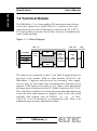
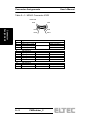
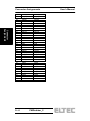
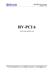
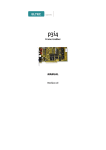
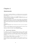
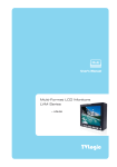
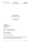
PMGrabber_2 Hardware Manual Revision 1A elektronik mainz Revision History Revision 1A Changes First Edition, valid for Hardware revision 1A, Date 27.04.2000 CW WARNING ! This equipment generates and can radiate radio frequencies. If not installed in accordance with the instruction manual, it may cause interference to radio communications. The equipment has not been tested for compliance with the limits for class A computing devices, pursuant to subpart J of part 15 of FCC rules, which are designed to provide reasonable protection against such interference, but temporary usage is permitted as per regulations. Operation of this equipment in a residential area is likely to cause interference, in which case the user, at his own expense is required to take whatever measures may be required to shield the interference. DISCLAIMER! The information in this document has been carefully checked and is believed to be entirely reliable. However, no responsibility is assumed for inaccuracies. ELTEC reserves the right to make changes to any products to improve reliability, function or design. ELTEC does not assume any liability arising out of the application or use of any product or circuit described in this manual; neither does it convey any license under its patent rights nor the rights of others. ELTEC products are not authorized for use as components in life support devices or systems intended for surgical implant into the body or intended to support or sustain life. Buyer agrees to notify ELTEC of any such intended end use whereupon ELTEC shall determine availability and suitability of its product or products for the use intended. ELTEC points out that there is no legal obligation to document internal relationships between any functional modules, realized in either hardware or software, of a delivered entity. This document contains copyrighted information. All rights including those of translation, reprint, broadcasting, photomechanical or similar reproduction and storage or processing in computer systems, in whole or in part, are reserved. 2000 ELTEC Elektronik AG, Mainz User's Manual Table of Contents Table of Contents 1 Specification ............................................................... 1—1 1.1 Main Features ......................................................... 1—1 1.2 Technical Details ..................................................... 1—2 1.3 Ordering Information................................................ 1—3 2 Connector Assignments.............................................. 2—1 2.1 Frontpanel Connector............................................... 2—1 2.2 Power Supply Connector X204................................. 2—3 2.3 PMC Connectors (PCIBus Connectors)..................... 2—4 3 Jumpers ...................................................................... 3—1 4 Technical Data .................................................................A PMGrabber_2 I Table of Contents User's Manual List of Tables Table 2—1: MIN-D Connector X203 .................................. 2—2 Table 2—2: Power Supply Connector X204 ....................... 2—3 Table 2—3: Pinout of PMC Connectors (PCIBus)............... 2—4 II PMGrabber_2 User's Manual Table of Contents List of Figures Figure 1—1: Block Diagram .............................................. 1—2 Figure 2—1: Connector Locations................................... 2—1 PMGrabber_2 III Table of Contents IV PMGrabber_2 User's Manual Specification Specification User's Manual 1 Specification 1.1 Main Features • Up to two color camera inputs for SVHS (Y/C)-or up to four input's for CVBS cameras • Real- time acquisition of images or image sequences directly into main memory of host computer • Single size PMC module • Power supply for cameras (12V) • PCI 2.1 compliant PMGrabber_2 1—1 Specification User's Manual Specification 1.2 Technical Details The PMGrabber_2 is a frame grabber PCI mezzanine card with two color-video inputs for use with SVHS (Y/C) cameras or four color video inputs for use with CVBS cameras. Based on the PC_EYE® 4 PC frame grabber it provides for the basic features of standard color video frame grabbing. Figure 1—1: Block Diagram SAA 7111 Y0/CVBS0 C0/CVBS1 Input MUX SAA 7146 Luminance ADC Y1/CVBS2 C1/CVBS3 Color Separation & Conversion To RGB Or YC (4:2:2) PMC Connector Scaler + DMA Controller Chrominance ADC The cameras are connected via the 15 pol. MIN-D (high density) at the front of the module. With its video decoder (SAA7111) the PMGrabber_2 digitizes and processes the incoming video signals one at a time. Its four inputs may be configured to function as four separate CVBS inputs or two pairs of Y/C inputs. After digitization the image data is transferred to the PCI DMA controller (SAA 7146). This controller is capable of rescaling the image data and transferring it into the hosts main memory or graphics card. It does this using selecable data formats such as RGB32, -24, -16, -15 (bit), YUV4:2:2, -4:4:4 (24-bit/pixel), or monochrome 8-bit. There is no additional image memory onboard the module. 1—2 PMGrabber_2 Specification Specification User's Manual 1.3 Ordering Information Hardware: PMGrabber_2 V-PMGR-200x Documentation: V-PMGR-992x Related products: PMGrabber_1 Order No. V-PMGR-100x Flexible PMC framegrabber module for standard monochrome cameras. PMGrabber_3 Order No. V-PMGR-300x PMC frame grabber for security applications with up to eight CVBS inputs. Appropriate CPU boards from ELTEC EUROCOM 138, BAB740, HiPerCam_ 2 PMGrabber_2 1—3 Specification User's Manual Specification 1—4 PMGrabber_2 User's Manual Connector Assignments 2 Connector Assignments J102 User EEPROM write protect Connector Assignments Figure 2—1: Connector Locations PMC Connectors X101 X102 PHILIPS SAA7146 MIN-D Connector X203 Video Input X204 12 Volt Power Supply 2.1 Frontpanel Connector The connector X203 located at the frontpanel is intended for analog video input. It has the same mechanical appearance as a VGA video output connector and should not be confused with the latter. To avoid damage to the hardware, do not connect a VGA monitor to X203! On pin 14 and 15 of X203 a voltage of +12V is delivered to power the camera(s).The current that can be drawn from each pin is limited by a PTC resistor (Imax ca. 500mA). It is recommended to power different cameras from different pins, to avoid to much load on one pin. PMGrabber_2 2—1 Connector Assignments User's Manual Table 2—1: MIN-D Connector X203 Front view Pin5 Connector Assignments Pin # 1 2 3 4 5 6 7 8 9 10 11 12 13 14 15 2—2 Pin1 Pin10 Pin6 Pin15 Pin11 Signal video input 0 (Y0) Video input 1 (C0) video input 2 (Y1) video input 3 (C1) signal ground signal ground signal ground signal ground reserved signal ground reserved signal ground signal ground power 0 power 1 SVHS camera 1 SVHS camera 2 PMGrabber_2 CVBS CVBS CVBS CVBS camera camera camera camera 1 2 3 4 do not connect do not connect +12V, 500mA max. +12V, 500mA max. User's Manual Connector Assignments If you intend to power your camera from the PMGrabber_2, the internal floppy type connector X204 has to be used. Use the cable 'H-PMGR-800A' coming with the module to establish a connection to the appropriate connector on the PMC carrier. Table 2—2: Power Supply Connector X204 View from top Pin# 1 2 3 4 Signal nc signal ground signal ground +12V Pin 4 PMGrabber_2 Pin 1 2—3 Connector Assignments 2.2 Power Supply Connector X204 Connector Assignments User's Manual 2.3 PMC Connectors (PCIBus Connectors) Table 2—3: Pinout of PMC Connectors (PCIBus) Connector Assignments Pin# 1 2 3 4 5 6 7 8 9 10 11 12 13 14 15 16 17 18 19 20 21 22 23 24 25 26 27 28 29 30 31 32 33 34 35 36 37 38 39 40 41 42 43 2—4 X101 PMGR-200 nc nc nc Conn. to TDI Conn. to TDO Ground Ground nc nc nc nc +3.3V RST# nc +3.3V nc nc Ground AD(30) AD(29) Ground AD(26) AD(24) +3.3V IDSEL AD(23) +3.3V AD(20) AD(18) Ground AD(16) C/BE(2)# Ground nc TRDY +3.3V Ground STOP# PERR Ground +3.3V nc C/BE(1)# spec. +12V TRST# TMS TDO TDI Ground Ground PCI-RSVD PCI-RSVD PCI-RSVD BUSMODE2# +3.3V RST# BUSMODE3# +3.3V BUSMODE4# PCI-RSVD Ground AD(30) AD(29) Ground AD(26) AD(24) +3.3V IDSEL AD(23) +3.3V AD(20) AD(18) Ground AD(16) C/BE(2)# Ground PMC-RSVD TRDY# +3.3V Ground STOP# PERR Ground +3.3V SERR# C/BE(1)# PMGrabber_2 User's Manual PMGR-200 Ground AD(14) AD(13) Ground AD(10) AD(8) +3.3V AD(7) nc +3.3V nc nc Ground nc nc Ground nc nc +3.3V Ground nc spec. Ground AD(14) AD(13) Ground AD(10) AD(8) +3.3V AD(7) PMC-RSVD +3.3V PMC-RSVD PMC-RSVD Ground PMC-RSVD PMC-RSVD Ground PMC-RSVD ACK64# +3.3V Ground PMC-RSVD Connector Assignments Pin# 44 45 46 47 48 49 50 51 52 53 54 55 56 57 58 59 60 61 62 63 64 Connector Assignments PMC Connectors (PCIBus connectors) Pin# 1 2 3 4 5 6 7 8 9 10 11 12 13 14 15 16 17 18 19 20 21 22 23 24 25 X102 PMGR-200 nc Testpoint 101 Ground INTA# nc nc nc +5V nc nc Ground nc CLK Ground Ground GNT# REQ# +5V nc AD(31) AD(28) AD(27) AD(25) Ground Ground spec. TCK -12V Ground INTA# INTB# INTC# BUSMODE1# +5V INTD# PCI-RSVD Ground PCI-RSVD CLK Ground Ground GNT# REQ# +5V V(I/O) AD(31) AD(28) AD(27) AD(25) Ground Ground PMGrabber_2 2—5 Connector Assignments Connector Assignments 26 27 28 29 30 31 32 33 34 35 36 37 38 39 40 41 42 43 44 45 46 47 48 49 50 51 52 53 54 55 56 57 58 59 60 61 62 63 64 2—6 C/BE(3)# AD(22) AD(21) AD(19) +5V nc AD(17) FRAME# Ground Ground IRDY# DEVSEL# +5V Ground nc nc nc PAR Ground nc AD(15) AD(12) AD(11) AD(9) +5V Ground C/BE(0)# AD(6) AD(5) AD(4) Ground nc AD(3) AD(2) AD(1) AD(0) +5V Ground nc C/BE(3)# AD(22) AD(21) AD(19) +5V V(I/O) AD(17) FRAME# Ground Ground IRDY# DEVSEL# +5V Ground LOCK# SDONE# SBO# PAR Ground V(I/O) AD(15) AD(12) AD(11) AD(9) +5V Ground C/BE(0)# AD(6) AD(5) AD(4) Ground V(I/O) AD(3) AD(29 AD(1) AD(0) +5V Ground REQ64# PMGrabber_2 User's Manual User's Manual Jumpers 3 Jumpers Jumpers There is only one jumper which may be utilized by the user: J102. Setting this jumper will activate write protection of the user portion within the modules revision EEPROM. If you intend to write your own user data into this device make sure J102 not be set. PMGrabber_2 3—1 Jumpers User's Manual Jumpers 3—2 PMGrabber_2 User's Manual Technical Data 4 Technical Data PMC: 32-bit, 33MHz - interface, PCI 2.2 - compliant Single slot module 3.3V operation of PCI - interface, 5V needed for internal circuits Connectors: Video inputs 2 x Y/C or 4 x CVBS on a 3-row 15-pin MIN-D, 1Vpp nom. 2 x 12V camera power supply with 500mA max. current each Technical Data Environmental Conditions: Storage temperature -20°C to +70°C Operating temperature 0°C to +45°C (2m/s forced air cooling) Maximum operating humidity 85% rel. Power requirements: 0.5A max., 0.3A typ. at +5VDC +-5% 1.0A max., 0.4A typ. at +3.3VDC +-5% PMGrabber_2 A Technical Data Technical Data B PMGrabber_2 User's Manual Support ELTEC Elektronik AG Support, Mainz/Germany Phone: +49 (6131) 918-520 Fax: +49 (6131) 918-196 E-Mail: [email protected] Web: http://www.eltec.com