1
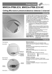
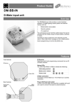
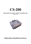
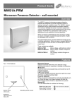
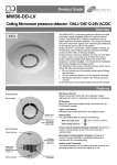
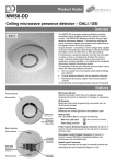
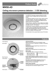
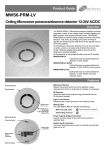
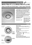
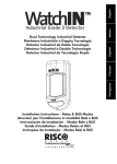
Product Guide MWS3A-KNX Ceiling microwave presence detector – KNX Overview The MWS3A-KNX microwave presence detector provides automatic control of lighting loads with optional manual control. The MWS3A-KNX detects movement using a highly sensitive microwave detector. This works by emitting low power microwave signals and measuring the reflections as the signals bounce off moving objects. The device is designed to be part of a KNX system. Features include. Two switch inputs to manually override the dimming levels and / or override the lights on or off. KNX programming mode accessible with IR handset and also by using the push switch on the back of the unit. Programmable logic block. This allows conditions to be set. For example: send the occupancy telegram only if the switch is pressed and the lux is low. Full scene selection functionality selectable via the IR handset (UHS7 ), eg: scene, on, off, raise and lower . All functionality is fully programmable using the KNX ETS commissioning software. Features Microwave Sensor Detects movement within the unit’s detection range, allowing load control in response to changes in occupancy. Front features Mounting Bezel IR Receiver Receives control and programming commands from an IR (infrared) handset. Light Level Sensor Measures the overall light level in the detection area Sensor Lens which covers... Microwave Sensor IR Receiver Light Level Sensor Status LEDs Retaining Spring KNX Communication LED Retaining Spring Walk Test LED active when movement is detected Valid IR setting received KNX Programming LED The LED lights when the device is placed in programming mode via the button or IR remote. In programming mode, the Status LED will mimic the programming LED (i.e. will be on for the duration of programming mode). Back features Switch Input Connector Status LEDs The LED flashes Red to indicate the following: KNX Program Button KNX Connector KNX Programming Mode Button Press to signal to the KNX network to enable the system to discover the device. This can also be done via the IR handset. Switch Input Connector Two inputs can be used to perform several configurable functions, for example, dim up / down, scene recall and also contribute to logic functions. Detection diagrams Ideal for large office or classroom Ideal for corridor or aisle applications Note. If the range is compromised by the ceiling construction / material. Add the supplied 20mm spacer ring. See page 3 for fitting details. Ideal for open plan areas and offices Installation Choosing a Suitable Location The detector should be sited so that the occupants of the room fall inside the detection pattern shown opposite). Avoid positioning the unit where direct sunlight may enter the sensor element. Do not site the sensor within 1m of any lighting, forced air heating or ventilation. Do not fix the sensor to an unstable or vibrating surface. Avoid metallic objects directly in front of the sensor head. 2 Installation The MWS3A-KNX is designed to be mounted using either: Flush fixing, or Surface fixing, using the optional Surface Mounting Box (part no. MWS3A-DBB). Both methods are illustrated below. Warning - be careful bending springs when mounting unit. Flush fixing 1 3 2 Hole Ø74mm 4 5 Attach cable clamp If the range is compromised by the ceiling construction / material. Add the supplied 20mm spacer ring. Surface fixing 1 2 3 4 Hole Ø30mm MAX Head locking 1 Remove metal locking clip from rear of unit. 2 Adjust head to required position. Push clip into position shown below to lock head. To remove clip, lever out with a small screwdriver. Wire stripping details Important Ensure that the cables are formed as shown before affixing the cable clamp. The clamp MUST clamp the outer sheath(s) only. Bend cores as shown. 3 Wiring diagram Switch inputs Note: low voltage only Fault finding Device will not enter programming mode Check the KNX connections and that the bus segment is powered. The bus voltage should be approximately 30V. Check that the programming LED illuminates when the button is pressed on the rear of the unit. What if the lighting does not turn ON? Check that the unit has been correctly added to the KNX system. Check that the sensitivity has been correctly set via ETS. Check any logic functions carefully for intended operation. If using the constant brightness controller, check that the light level measured by the sensor is lower than the required threshold. If the detection range is smaller than expected, check the diagram on page 2. Adjusting the angle of the sensor head slightly may improve the detection range. If still reduced it may be compromised by the ceiling construction / material. Add the supplied 20mm spacer ring. See page 3 for fitting details. HINT: The Walk Test LED function can be used to check that the unit is detecting movement in the required area. What if the lighting does not turn OFF? Check any logic functions carefully for intended operation. If using the constant brightness controller, check that the light level measured by the sensor is lower than the required threshold. Ensure that the area is left unoccupied for longer than the Time Out Period. Ensure that the sensor is not adjacent to circulating air, heaters or lamps. 4 IR operation UHS5 Programming IR Handset. See below for programmable functions. UHS7 User IR Handset. This handset can be used for selecting scenes, on, off, raise and lower. See user guide for full programming details. For most basic programming operations the UHS5 handset can be used and the following procedures are based on using this device. Point the handset at the Sensor and send the required programming commands to the unit as shown below. Valid commands will be indicated by a red LED flash. See page 1 for details of other LED responses. Note: other functions on the UHS5 which are not shown below are not applicable to this product. Number of Shift key presses Parameter Name Default Value 0 SHIFT 1 1 SHIFT 2 SHIFT 1 2 SHIFT 2 SHIFT 1 3 SHIFT 2 SHIFT 1 UHS5 Handset Graphics Description SHIFT 2 Button Activation On / Raise On Raise Turn lights on or to raise lights. Off / Lower Off Lower Turn lights off or to lower lights. On Off When set to On this causes a red LED to flash on the sensor when it detects movement. Use this feature to check for adequate sensitivity levels. Note. Will be cancelled by ETS or a power cycle. Selects mode Deselects mode Press to signal to the KNX network to enable the system to discover the device. Note. The programming mode is cancelled automatically when ETS finishes programming the device. Walk test KNX Programming Mode Off 5 KNX function and configuration Introduction A presence detector monitors the detection zone for occupancy, and causes one or more actions to be executed when a person enters the detection area. In their simplest form, presence detectors could be used to turn on a light when a person enters a room, and to turn it off again after the person leaves. This range of presence detectors use the same basic infra-red or microwave detection technology, but make use of the KNX system to communicate with other devices. The KNX standard defines how devices should communicate with each other, allowing systems to be constructed using components from many different manufacturers. The standard also guarantees that a presence detector from one manufacturer will effectively control a lighting dimmer or HVAC system from another. Central to the KNX system is the ETS configuration tool. This Windows application allows an installer to configure all functions of each individual device in the system, and also how triggers and data are passed between different devices. For instance, the tool can be used to set the sensitivity of the presence detector, and can be associated with a particular lighting on-off channel. When someone walks into the room, the light will be turned on, and turned off after a configurable delay. The tool maintains a configuration database for the entire system, and downloads this configuration to each system element. Functional Description The presence detector consists of a infra-red detector element, reflected light sensor and two volt-free switch inputs. The KNX application has been designed to offer the installer a variety of useful functions such as movement detection, constant brightness control, user timers, lighting scene recall via infra-red handset and simple transmission of input states. Three ETS-configurable logic controllers allow the installer to fine-tune the behaviour of the detector in response to sensor state, switch inputs and KNX group objects offering a level of control that would normally require an external logic block. The various functions are grouped in ETS as follows: General settings Basic settings such as walk test LED enable/disable, sensor sensitivity, movement timeout and light sensor calibration. Switch inputs Defines the behaviour when each of the switch inputs change state, e.g. dimming, switching or scene recall. Switch inputs may also be used as inputs to the three logic controllers. Infra-red scene control Defines which KNX scenes are mapped to the scene recall button on the UHS7 remote control, and how the on/ off buttons should behave. Logic controller 1/2 (switch/scene) Defines a custom logic function using simple drop-down boxes to send either switch or scene recall telegrams in response to the state of various inputs, sensor state and KNX group objects. Logic controller 3 (brightness) Defines a custom logic function using simple drop-down boxes to determine a brightness target value that should be maintained. The logic function may use various inputs, sensor state and KNX group objects to determine which brightness target should be active. User timer 1/2 Each timer can be configured with up to two logic functions: one to start the timer, and one to stop it. The timer period can be independently set, and commands can be sent when the timer starts, is stopped or when the time period expires. Basic movement detection Raw switch output from the movement detector, suitable for signalling security systems or master sensors when used in master-slave mode. For larger rooms, several Presence Detectors can be used to increase the coverage area. In this configuration, one presence detector acts as the master, and all other detectors act as slaves. When movement is detected by any of the slave detectors, a telegram is sent to the master via the KNX bus. The master detector uses this information as part of a logic expression to send dimming, scene recall or brightness commands to the controlled device. The movement timeout period is defined on the master device; slave devices simply need to send a telegram whenever movement is sensed. 6 KNX function and configuration Configuration Configuration of the presence detector and associated logic functions is via the ETS tool, available from the KNX association. Start the process by downloading the device catalogue from www.cpelectronics.co.uk and importing it into ETS. Once imported, the device can be added to a project and assigned an individual address in the normal way. The detector is configured via the Parameters tab, and all options are grouped by function as previously described. Group objects will be automatically enabled and disabled based on the chosen parameters. Once the relevant parameters have been configured, group addresses may be assigned to detector functions, allowing the detector to communicate with other devices on the KNX bus. Finally, a download function is performed to write the settings and configuration to the detector. The detector may be placed into programming mode using the programming pushbutton on the rear of the unit, or by using the optional UHS5 infra-red remote control. When the device enters programming mode, a red LED is illuminated on the rear of the unit, and also through the sensor aperture. Once programmed, the device will leave programming mode automatically. General settings The general configuration tab contains settings which relate to general operation of the detector, such as sensitivity, timeouts and whether the walk test LED should be enabled or disabled. Settings made in this section will also affect inputs to the various controllers detailed below, with the exception of the basic movement detection controller. The detector contains a light sensor for use as part of the constant brightness controller, and to send light level readings to other devices on the KNX bus. It is important to note that the light sensor requires calibration in order to produce real lux values, and this calibration should take place once installed using a light meter. To perform a calibration, the light level multiplier should initially be set to 1.0. The room should be furnished as reflected light (e.g. from uncovered floor tiles) will dramatically change the measured value. Using the ETS group monitor, record several lux values for different levels of illumination, with the light meter placed normally within the room. It will be necessary to assign a group address to the light level output group object. Once these values have been recorded, the multiplier can be calculated as follows: Multiplier = lightmetervalue detectorvalue For example. Light meter value Detector value Calculated Multiplier 590 534 1.105 928 816 1.137 An average of the calculated multiplier values yields a multiplier of 1.121. 7 General settings Setting Options Description Sensor walk test LED Disable Enable Enable or disable the sensor walk test LED, triggered when movement is detected. This is useful for commissioning, (or if the detector is to be used in bedrooms). Note that the walk test function can also be turned on and off via infra-red remote control. Sensor sensitivity 0 to 9 Increase or decrease the detector's sensitivity to movement. 0 is least sensitive, 9 is most sensitive. The sensitivity can be overridden via infra-red remote, but will be overwritten when parameters are updated via ETS. Lux multiplier Floating point Value to multiply raw light level readings by to obtain true lux value. In practice, this will need to be set with the aid of a light meter in the environment that the detector is used in, as reflected light and even choice of furnishings will dramatically affect the readings obtained. Send light level telegrams every 0 – 65535s Defines how often to send light level telegrams. It is only possible to send cyclically: immediate transmission would overload the bus. Group Object Data Type Description Light level output 9.4 DPT_Value_Lux Simple cyclical output of current brightness in lux. Switch inputs The switch inputs parameters are used to define the behaviour when the two volt-free switch inputs are connected. The inputs can be used to send dimming commands, recall scenes or send simple switch (on/off) telegrams. It should be noted that these switch inputs can be used as part of logic functions if required. Setting Options Description Switch input 1 close action Send 'dim up' command Send 'dim down' command Recall scene number Send 'on' command Send 'off' command Send 'on' command cyclically Send 'off' command cyclically Do nothing Defines what type of command should be sent when switch input 1 is closed. Switch input 1 close scene number 1 – 64 Scene number to recall when switch input 1 is closed Switch input 1 open action Send 'dim up' command Send 'dim down' command Recall scene number Send 'on' command Send 'off' command Send 'on' command cyclically Send 'off' command cyclically Do nothing Defines what type of command should be sent when switch input 1 is opened. Switch input 1 open scene number 1 – 64 Scene number to recall when switch input 1 is opened. Switch input 1 touch action Toggle on/off Toggle scene A/B Do nothing Defines what command is sent when the button connected to the switch input is touched (i.e. pressed and released) Switch input 1 scene number 'A’ 1 - 64 Scene number to recall when scene 'A' is selected. Switch input 1 scene number 'B’ 1 - 64 Scene number to recall when scene 'B' is selected. Switch input 1 hold action Dim up/down Dim up Dim down Do nothing Defines what command is sent when the button connected to the switch input is held. This may be specified in addition to the touch action above Switch input 2 close action Send 'dim up' command Send 'dim down' command Recall scene number Send 'on' command Send 'off' command Send 'on' command cyclically Send 'off' command cyclically Do nothing Defines what type of command should be sent when switch input 2 is closed. 8 Switch inputs (continued) Setting Options Description Switch input 2 close scene number 1 – 64 Scene number to recall when switch input 2 is closed. Switch input 2 close action Send 'dim up' command Send 'dim down' command Recall scene number Send 'on' command Send 'off' command Send 'on' command cyclically Send 'off' command cyclically Do nothing Defines what type of command should be sent when switch input 2 is closed. Switch input 2 close scene number 1 – 64 Scene number to recall when switch input 2 is closed. Switch input 2 open action Send 'dim up' command Send 'dim down' command Recall scene number Send 'on' command Send 'off' command Send 'on' command cyclically Send 'off' command cyclically Do nothing Defines what type of command should be sent when switch input 2 is opened. Switch input 2 open scene number 1 – 64 Scene number to recall when switch input 2 is opened. Switch input 2 touch action Toggle on/off Toggle scene A/B Do nothing Defines what command is sent when the button connected to the switch input is touched (i.e. pressed and released) Switch input 2 scene number 'A’ 1 - 64 Scene number to recall when scene 'A' is selected. Switch input 2 scene number 'B’ 1 - 64 Scene number to recall when scene 'B' is selected. Switch input 2 hold action Dim up/down Dim up Dim down Do nothing Defines what command is sent when the button connected to the switch input is held. This may be specified in addition to the touch action above Dim up/dim down step percentage 100% 50% 25% 12.5% 6.25% 3.125% 1.5625% The percentage to add or subtract from the current dimmer value when the relevant button is pressed. Smaller percentages offer finer-grained control, but require the user to press the button more times to change the light level. Send switch 1 cyclical telegrams every 0 – 65535s Defines how often to send switch state telegrams if cyclical sending has been chosen. Send switch 2 cyclical telegrams every 0 – 65535s Defines how often to send switch state telegrams if cyclical sending has been chosen. Group Object Data Type Description Switch 1 scene recall 17.1 DPT_SceneNumber Scene number transmitted when switch 1 changes state if in scene recall mode. Switch 2 scene recall 17.1 DPT_SceneNumber Scene number transmitted when switch 2 changes state if in scene recall mode. Switch 1 state output 1.1 DPT_Switch On/off switch state telegram if configured. Switch 2 state output 1.1 DPT_Switch On/off switch state telegram if configured. Switch 1 dimming control output' 3.7 DPT_Control_Dimming Dimming control output if switches are configured for dim up/dim down operation. Switch 2 dimming control output' 3.7 DPT_Control_Dimming Dimming control output if switches are configured for dim up/dim down operation. 9 Infra-red scene control The infra-red scene control parameters are used to configure the scene recall behaviour when the sensor is used with the UHS7 remote control handset. This handset provides eight scene recall buttons, dim up/down buttons and on/off buttons. As KNX defines a maximum of 64 scenes per group object, the parameter page allows these scenes to be mapped to the 8 remote control buttons. In addition, the on/off buttons may be used to transmit a simple switch telegram, or alternatively used to recall an additional two scenes. This would allow the 'off' scene to preserve a low level of light at all times. Dim up/dim down buttons are provided for direct control of the dimmer; the dimming interval may also be set. Note that variations to brightness using this method will not be 'saved' by the dimmer; subsequent scene recalls will revert to programmed values. Setting Options Description On/off button command type Switch Scene Recall Defines whether the on/off buttons should be used to send switch or scene recall telegrams Map 'on' button to scene 1 – 64 Scene number to be associated with 'on' button Map 'off' button to scene 1 – 64 Scene number to be associated with 'off' button Map button 1 to scene 1 – 64 Scene number to be associated with IR button 1 Map button 2 to scene 1 – 64 Scene number to be associated with IR button 2 Map button 3 to scene 1 – 64 Scene number to be associated with IR button 3 Map button 4 to scene 1 – 64 Scene number to be associated with IR button 4 Map button 5 to scene 1 – 64 Scene number to be associated with IR button 5 Map button 6 to scene 1 – 64 Scene number to be associated with IR button 6 Map button 7 to scene 1 – 64 Scene number to be associated with IR button 7 Map button 8 to scene 1 – 64 Scene number to be associated with IR button 8 Dim up/dim down step percentage 100% 50% 25% 12.5% 6.25% 3.125% 1.5625% The percentage to add or subtract from the current dimmer value. Smaller percentages offer finergrained control, but require the user to press the button more times to change the light level Group Object Data Type Description Scene recall output 17.1 DPT_SceneNumber Scene number transmitted when IR scene button is pressed, or on/off buttons in scene recall mode. Switch output 1.1 DPT_Switch Switch on/off telegram transmitted when IR on/off buttons are pressed. Dimming control output 3.7 DPT_Control_Dimming Dimming telegram transmitted when IR dim up/dim down buttons are pressed. The increment can be configured by the installer. 10 Logic controller 1 / 2 (switch/scene) The switch/scene logic controller tabs allow up to two independent switch/scene recall channels to be configured. Each channel receives the same inputs from the movement sensor and Switch input connections, but have separate KNX group objects. The behaviour of the channel is defined by a logic expression which ultimately evaluates to true or false, triggering one of two actions. Configuring the logic expression is no more complicated than writing a sentence. Drop-down boxes allow various conditions, terms and actions to be chosen. If appropriate, additional drop-down boxes will appear to allow the expression to be expanded. The most basic configuration is as follows: IF (Movement Detected) THEN Send 'On' Telegram ELSE Send 'Off' Telegram This statement would cause the 'on' telegram to be sent to the corresponding channel's KNX output object when movement was detected, and then an 'off' telegram to be sent once the movement timeout has expired. A more complicated example would use inputs to enable or disable the movement detector remotely, for instance: IF (Movement Detected AND Group Enable Input Set) OR (Switch 1 Input Closed) THEN Send 'On' Telegram ELSE Send 'Off' Telegram This statement would cause the 'on' telegram to be sent if movement had been detected and the detector has been remotely enabled, or if the local Switch 1 input was set. Otherwise the 'off' telegram would be sent. This example would be useful in a building in night mode where all detectors are normally switched off unless a local override switch has been operated. The KNX slave input can be used as an input from another detector. When an 'on' telegram is received by this group object, the sensor considers the slave input to be set until the timeout period (in general settings) has expired. Any 'off' telegrams are ignored. This allows several slave detectors to be linked with a single master detector. The controller can also be configured to send a scene recall telegram, for instance recalling a bright scene when Setting Options Description Enable/disable logic controller 1/2 Disable Enable Enable or disable this movement channel. Logic conditions Movement detected Movement cleared Group enable input set Group enable input clear Group slave input set Group slave input clear Switch 1 input closed Switch 1 input opened Switch 2 input closed Switch 2 input opened Brightness above lux threshold 'A' Brightness below lux threshold 'A' Brightness above lux threshold 'B' Brightness below lux threshold 'B' Logic conditions may be combined using logic terms to form an expression, which is used to perform one action when the expression is true, and another when the expression is false. Logic terms AND OR THEN Logic terms are used to define the function. The AND term indicates that ALL inputs must be true for the expression to be true, whereas the OR term will return true if one of the inputs is true. The THEN term is used to indicate that the expression is complete, and that the next item is an action. Logic actions Send 'on' telegram Send 'off' telegram Send 'on' telegram cyclically Send 'off' telegram cyclically Recall scene 'A' Recall scene 'B' Set brightness level ‘A' Set brightness level ‘B Send nothing When the logic expression is evaluated, an action may be associated with both the if-then and else portions of the expression, i.e. Send 'on' telegram if the expression is true, else Send 'off' telegram. Movement timeout source ETS parameter or Group object Movement timeout may be set statically using ETS, or alternatively may be changed by other devices on the KNX bus Movement timeout 0 – 32767s, 0 - 546mins, 0 - 9hrs How long to wait after the last movement is detected before signalling a 'movement cleared' state Brightness threshold ‘A’ Floating point Lux value to be used as comparison value in logic function, e.g. above or below this value. Brightness threshold ‘B’ Floating point Lux value to be used as comparison value in logic function, e.g. above or below this value. Scene 'A' 1 - 64 KNX scene number to be recalled on command. Scene 'B' 1 - 64 KNX scene number to be recalled on command.. 11 Logic controller 1 / 2 (switch/scene) (continued) Setting Options Description Brightness setting 'A' 0 - 100% The brightness percentage to send to the dimmer when required. Brightness setting 'B' 0 - 100% The brightness percentage to send to the dimmer when required. Send cyclical telegrams every 0 – 65535s How often to send cyclical telegrams if selected as part of the logic function. Group Object Data Type Description Logic controller 1 (motion) - Switch state output 1.1 DPT_Switch The main output from the channel's logic expression. Logic controller 1 (motion) - Scene recall output 17.1 DPT_SceneNumber Configured scene number is sent via this group object if required. Logic controller 1 (motion) - Enable input 1.3 DPT_Enable Global enable/disable input for this channel allowing remote devices to participate in the logic function. Logic controller 1 (motion) - Slave trigger input 1.1 DPT_Switch Slave input for this channel, allowing the state of other detectors to be read as part of the logic function. Logic controller 1 (motion) - Movement timeout input 7.5 DPT_TimePeriodSec Allows a remote device to change the movement timeout, if this option is selected. The value must be in seconds. Logic controller 1 (motion) - Absolute dimmer percentage 5.4 DPT_Percent_U8 Configured dimmer percentage is sent via this group object if required. Logic controller 2 (motion) - Switch state output 1.1 DPT_Switch The main output from the channel's logic expression. Logic controller 2 (motion) - Scene recall output 17.1 DPT_SceneNumber Configured scene number is sent via this group object if required. Logic controller 2 (motion) - Enable input 1.3 DPT_Enable Global enable/disable input for this channel allowing remote devices to participate in the logic function. Logic controller 2 (motion) - Slave trigger input 1.1 DPT_Switch Slave input for this channel, allowing the state of other detectors to be read as part of the logic function. Logic controller 2 (motion) - Movement timeout input 7.5 DPT_TimePeriodSec Allows a remote device to change the movement timeout, if this option is selected. The value must be in seconds. Logic controller 2 (motion) - Absolute dimmer percentage 5.4 DPT_Percent_U8 Configured dimmer percentage is sent via this group object if required. 12 Logic controller 3 (brightness) The brightness logic controller aims to maintain a uniform brightness in the sensor area at all times (known as daylight linking, daylight harvesting or maintained illuminance). Two brightness targets can be defined, subject to a successful calibration (as detailed earlier). In similar fashion to the movement controllers, a logic expression can be constructed to choose which brightness target the controller should try to achieve. This would allow the lights to be turned off overnight, or for the lights to be made brighter when the room is occupied. The controller sends an 8-bit absolute percentage value to the dimmer. The installer may choose suitable values for the dimming increment and interval: these values should be chosen to minimise dimmer oscillation and response time. A deadband setting prevents the controller from making unnecessary adjustments. It is also possible to set a brightness target via a KNX group object, allowing the brightness target to be controlled from elsewhere. This might be useful in combination with a room reservations system, or to make the lights dimmer at weekends. Dimming telegrams are sent when required by the controller; the controller will not send dimming telegrams when the measured light level is close to the target value, subject to the deadband setting. Setting Options Description Enable/disable logic controller 3 Disable Enable Enable or disable the logic controller function. Logic conditions Movement detected Movement cleared Group enable input set Group enable input clear Group slave input set Group slave input clear Switch 1 input closed Switch 1 input opened Switch 2 input closed Switch 2 input opened Logic conditions may be combined using logic terms to form an expression, which is used to perform one action when the expression is true, and another when the expression is false. Logic terms AND OR THEN Logic terms are used to define the function. The AND term indicates that ALL inputs must be true for the expression to be true, whereas the OR term will return true if one of the inputs is true. The THEN term is used to indicate that the expression is complete, and that the next item is an action. Logic actions Set brightness target A Set brightness target B Set remote brightness target Set dimmer on Set dimmer off When the logic expression is evaluated, an action may be associated with both the if-then and else portions of the expression, i.e. Set brightness target 1 if the expression is true, else Set brightness target 2. Movement timeout source ETS parameter or Group object Movement timeout may be set statically using ETS, or alternatively may be changed by other devices on the KNX bus Movement timeout 0 – 32767s, 0 - 546mins, 0 - 9hrs How long to wait after the last movement is detected before signalling a 'movement cleared' state Brightness target A Floating point Target value in lux for the brightness controller to aim for. Brightness target B Floating point Target value in lux for the brightness controller to aim for. Telegram interval 0 – 65535 milliseconds How often to send commands to the dimmer when varying the brightness. Dimming increment 100% 50% 25% 12.5% 6.25% 3.125% 1.5625% The amount by which each subsequent dimming telegram raises or lowers the light level. Typically a small value will be used here, but will depend on the environment. Large values may cause the dimmer to oscillate between light and dark. Dimming deadband Floating point Deadband value in lux within which the controller will not attempt to vary the light output. Group Object Data Type Description Percentage output 5.4 DPT_Percent_U8 Brightness control for connected dimmer. The constant brightness controller will increase or decrease this value depending on the target selected Enable input 1.3 DPT_Enable Global enable/disable input for this channel allowing remote devices to participate in the logic function. Slave trigger input 1.1 DPT_Switch Slave input for this channel, allowing the state of other detectors to be read as part of the logic function. Movement timeout input 7.5 DPT_TimePeriodSec Allows a remote device to change the movement timeout, if this option is selected. The value must be in seconds. Target lux input 9.4 DPT_Value_Lux Brightness target value set by an external device, rather than an internal preset Target lux output 9.4 DPT_Value_Lux Brightness target value selected by logic function, for use by other devices. 13 User timer 1/2 Two user-configurable timers may be used to send commands based on timed events. Each timer may be started and stopped using independent logic expressions, for instance starting a timer when movement is detected, and stopping it if a final exit switch is closed. Once started, a timer will run until it expires, or is stopped. If the 'start' condition is matched again (for instance, additional motion is detected), then the time period will be reset. Commands may be attached to three timer events: timer start, timer stop and timeout. These commands may be used to switch a remote device on or off, set a scene or set a brightness level. It is possible to use both timers together to achieve a three-stage illumination profile. Setting Options Description Timer start logic expression Movement detected Movement cleared Group enable input set Group enable input clear Group slave input set Group slave input clear Switch 1 input closed Switch 1 input opened Switch 2 input closed Switch 2 input opened Brightness above lux threshold 'A' Brightness below lux threshold 'A' Brightness above lux threshold 'B' Brightness below lux threshold 'B' Logic conditions may be combined using logic terms to form an expression which, when true, starts (or restarts) the timer. There is no action when the expression evaluates to false. Logic terms AND OR THEN Logic terms are used to define the function. The AND term indicates that ALL inputs must be true for the expression to be true, whereas the OR term will return true if one of the inputs is true. The THEN term is used to indicate that the expression is complete, and that the next item is an action. Timer stop logic expression Movement detected Movement cleared Group enable input set Group enable input clear Group slave input set Group slave input clear Switch 1 input closed Switch 1 input opened Switch 2 input closed Switch 2 input opened Brightness above lux threshold 'A' Brightness below lux threshold 'A' Brightness above lux threshold 'B' Brightness below lux threshold 'B' Logic conditions may be combined using logic terms to form an expression which, when true, stops the timer. There is no action when the expression evaluates to false. Logic terms AND OR THEN Logic terms are used to define the function. The AND term indicates that ALL inputs must be true for the expression to be true, whereas the OR term will return true if one of the inputs is true. The THEN term is used to indicate that the expression is complete, and that the next item is an action. Movement timeout source ETS parameter or Group object Movement timeout may be set statically using ETS, or alternatively may be changed by other devices on the KNX bus Movement timeout 0 – 32767s, 0 - 546mins, 0 - 9hrs How long to wait after the last movement is detected before signalling a 'movement cleared' state Brightness threshold ‘A’ Floating point Lux value to be used as comparison value in logic function, e.g. above or below this value. Brightness threshold ‘B’ Floating point Lux value to be used as comparison value in logic function, e.g. above or below this value. Timer duration 0 – 32767s, 0 - 546mins, 0 - 9hrs How long the timer remains active. Once started, the timer will run for the duration, then signal a timeout. If the start condition is set again, then the timer will be re-started. If the timer is stopped, the timeout condition will not be reached. Action on timer start Send 'on' telegram Send 'off' telegram Set scene number Set dimmer value Do nothing Defines the command to send when the timer event occurs. Only one command will be sent for each event - for instance, if a timer start event has been sent, the timer must be stopped or must time out before another start event will be triggered. Scene # 1 - 64 KNX scene number to be recalled on command. Brightness 0 - 100% The brightness percentage to send to the dimmer when required. 14 User timer 1/2 (continued) Setting Options Description Action on timer stop Send 'on' telegram Send 'off' telegram Set scene number Set dimmer value Do nothing Defines the command to send when the timer event occurs. Only one command will be sent for each event - for instance, if a timer start event has been sent, the timer must be stopped or must time out before another start event will be triggered. Scene # 1 - 64 KNX scene number to be recalled on command.. Brightness 0 - 100% The brightness percentage to send to the dimmer when required. Group Object Data Type Description User timer 1 - Switch state output 1.1 DPT_Switch On/off command sent from timer start, stop and timeout events if configured. User timer 1 - Scene recall output 17.1 DPT_SceneNumber Scene preset sent from timer start, stop and timeout events if configured. User timer 1 - Absolute dimmer percentage 5.4 DPT_Percent_U8 Preset dimmer percentage sent from timer start, stop and timeout events if configured. User timer 1 - Enable input 1.3 DPT_Enable Global enable/disable input for this channel allowing remote devices to participate in the logic function. User timer 1 - Slave trigger input 1.1 DPT_Switch Slave input for this channel, allowing the state of other detectors to be read as part of the logic function. User timer 1 - Movement timeout input 7.5 DPT_TimePeriodSec Allows a remote device to change the movement timeout, if this option is selected. The value must be in seconds. User timer 2 - Switch state output 1.1 DPT_Switch On/off command sent from timer start, stop and timeout events if configured. User timer 2 - Scene recall output 17.1 DPT_SceneNumber Scene preset sent from timer start, stop and timeout events if configured. User timer 2 - Absolute dimmer percentage 5.4 DPT_Percent_U8 Preset dimmer percentage sent from timer start, stop and timeout events if configured. User timer 2 - Enable input 1.3 DPT_Enable Global enable/disable input for this channel allowing remote devices to participate in the logic function. User timer 2 - Slave trigger input 1.1 DPT_Switch Slave input for this channel, allowing the state of other detectors to be read as part of the logic function. User timer 2 - Movement timeout input 7.5 DPT_TimePeriodSec Allows a remote device to change the movement timeout, if this option is selected. The value must be in seconds. 15 Basic movement detection The basic movement detection parameters are designed to provide raw access to the movement sensor itself. Movement detection by this function is not affected by the movement timeout parameter in the General parameters settings section – i.e. an telegram indicating an absence of movement will be sent relatively quickly. 'For operation as a slave device in a multi-sensor environment, it is necessary to configure the sensor to send an 'on' command when movement is detected. There is no need to configure the corresponding 'off' command, as this timeout is handled by the master detector. The switch state group object should be linked with the corresponding slave input on the master detector. Setting Options Description When movement detected Send 'on' command Send 'off' command Send 'on' command cyclically Send 'off' command cyclically Do nothing Defines which switch telegram should be sent when movement is detected. When movement cleared Send 'on' command Send 'off' command Send 'on' command cyclically Send 'off' command cyclically Do nothing Defines which switch telegram should be sent when movement is no longer detected. Send cyclical telegrams every 0 – 65535s Defines how often to send switch state telegrams if cyclical sending has been chosen. Group Object Data Type Description Movement state output 1.1 DPT_Switch Switch state transmitted when movement is detected, or movement is no longer detected. Note that this is the raw sensor state - timeouts do not apply 16 This page intentionally left blank 17 Technical data Dimensions Weight Supply Voltage Current consumption See diagrams opposite 0.15kg 30V DC via KNX bus 28.8mA MWS3A-KNX Note. Microwave sensors draw more current from the bus than a typical KNX device. Please ensure that the bus power supply has sufficient capacity to accommodate this device. 1.2mm2 (22swg) via KNX connector Terminal Capacity KNX Temperature Humidity Material (casing) Type IP rating -10ºC to 35ºC 5 to 95% non-condensing Flame retardant ABS and PC/ABS Class 2 IP40 Safety The microwave radiation emitted by these units is extremely low power and complies with ANSI standard “IEEEC95.1-1999 Standard for Safety Levels with Respect to Human Exposure to Radio Frequency Electromagnetic Fields 3kHz 300GHz.” Compliance EMC-2004/108/EC LVD-2006/95/EC MWS3A-DBB Microwave frequency compatibility The allowable frequency of operation of this product is different depending on region. Please select the correct order code using the table below. Suffix Region Frequency blank UK, China, India, Middle East, Malaysia, Hong Kong, Singapore 10.587GHz -R2 Australia and all of Europe except: UK, France, Portugal, Germany, Switzerland, Austria, Slovak Republic, Republic of Ireland 10.525GHz -R3 France, Portugal, Switzerland 9.900GHz -R4 Germany, Austria, Slovak Republic 9.350GHz -R5 Republic of Ireland 10.41GHz Part numbers Detector Accessories Part number MWS3A-KNX MWS3A-DBB UHS5 UHS7 Description Ceiling microwave presence detector – KNX Surface mounting box Programming IR handset User IR handset IMPORTANT NOTICE! This device should be installed by a qualified electrician in accordance with the latest edition of the IEE Wiring Regulations and any applicable Building Regulations. Due to our policy of continual product improvement CP Electronics reserves the right to alter the specification of this product without prior notice. 18 C.P. Electronics Ltd Brent Crescent London NW10 7XR United Kingdom Tel: + 44 (0) 333 900 0671 Fax: + 44 (0) 333 900 0674 www.cpelectronics.co.uk [email protected] Ref: #WD714 Issue 3