1
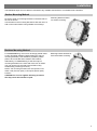
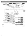
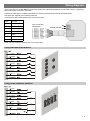
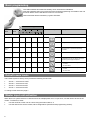
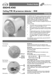
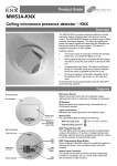
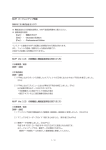
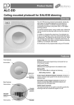
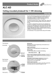
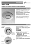
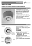
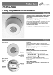
Product Guide DM-BB-IN D-Mate input unit Overview The DM-BB-IN Input Unit provides a control interface between a D-Mate lighting control system and external devices such as: Button/switch scene plates Security systems AV equipment The unit features seven Volt-free switch inputs that can be activated by the contact closure of push-buttons, switches, or relays. Activating an input causes the unit to transmit a scene, raise or lower light levels messages to the D-Mate system. Scene programming is via the UNLCDHS only. Features IR Receiver Receives control and programming commands from an IR (infrared) handset. Front features IR Receiver Status LEDs The LEDs flash Green or Red to indicate the following: Valid setting received Button press / release Status LEDs Factory reset D-Mate connection Connection to the D-Mate bus. The D-Mate bus is polarity insensitive. Back features Plug-in RJ45 lead and socket D-Mate connection Plug-in RJ45 lead and socket A short 8 core flat cable with plug that is supplied with each unit, used to connect the inputs to external devices. D-Mate D-Mate is a Lighting Control System suitable for small to medium scale applications offering the following key benefits: 4 independently dimmable lighting circuits. An additional 4 circuits can be programmed via the UNLCDHS. Scene setting - 4 user programmable scenes (plus an ‘off’ scene) per Scene plate. Scene recall via push-button Scene Plates, Input Units or IR handsets Presence and absence operation using detectors Lux switching and lux dimming (maintained illuminance) operation Introduction Devices within the D-Mate system communicate via a simple two wire data bus. The bus is powered via the D-Mate PSU and data is passed between devices using a format based around the DALI standard. The bus operates at a nominal voltage of 16 Volts DC which serves to provide operating power to each device connected to the bus. A maximum current of 200mA is available from the PSU. Therefore, in any D-Mate system, the maximum number of devices will be dependant on the total current consumption of all devices, including ballasts. Note: The use of additional D-Mate PSUs or third party PSUs with a higher current rating is not permitted. The output from the DM-SL-PSU is fully isolated from the mains input and may be regarded as an SELV device. However, as DALI ballasts only offer basic insulation, all devices on the D-Mate bus must be wired as if carrying mains potential. Physical requirements Data bus connections between devices must be made using suitable mains-rated two-core cable, such as two-core flex or bell wire. The minimum recommended core size is 0.75mm 2 for most applications. The data bus may be wired using any convenient network topology (e.g. line, star or tree). However, whichever topology is used, the total length of all cable (including spurs) within a system should not exceed 200m. There is no requirement to use screened cable. However, the routing of cables through electrically ‘noisy’ environments should be avoided to prevent possible interference on the bus. The data bus/power connections to all D-Mate devices are designed to operate correctly with reversed polarity. However, it is good practice to ensure all devices are wired with correct polarity. DALI and DSI ballasts are tolerant to reversed polarity, however, 1-10V ballasts are not. Multiple Device Control (Master and Slaves) It is possible to use multiple D-Mate control devices, such as detectors and plates in a system. For example there may be a need to have two plates in a room where the master plate controls all the circuits in the room but the slave plate is used to control a subset of circuits. An application of this would be where there are two detectors in a large room, where one would be the master and the other the slave. Where multiple control devices are used on the same circuit, one device must be designated the ‘master’. This is the device that is responsible for sending control messages to the Addressers. The master device also stores the levels for each Scene for the circuit(s) it controls. The other control devices on that circuit must be designated as ‘slaves’. These do not control the Addressers directly, but send messages to the master device which then sends messages to the Addressers. Where a detector exists on a circuit it must always be the master device, with any additional detectors or scene plates configured as slaves. Where a single detector is used with one more scene plates, it will automatically set the plates to slaves for the corresponding circuits. When there are no detectors in a system and only plates or input units, one of the plates or input units will need to be set as the master. To set the input unit as a master see page 7. 2 Installation The DM-BB-IN Input Unit can either be mounted to any suitable solid surface or concealed inside a backbox. Surface Mounting Method Fit the two snap-on mounting brackets on the back side of the unit as shown. Mounting bracket location for surface mounting. Use the holes in the mounting brackets to affix the unit to a wall or other solid surface using suitable screw fixings. Backbox Mounting Method For unsecured fixing, the unit can be simply placed inside a UK or European backbox (without fitting the snap-on mounting brackets). This enables a proprietary switch plate to be connected and screwed to the backbox. Mounting bracket location for secured backbox mounting. Alternatively, for secured fixing, fit the two snap-on mounting brackets on the front side of the unit as shown. The unit can then be secured to the backbox using suitable fixing screws (up to M3.5). NOTE: The mounting bracket holes are spaced to suit either a UK (60.3mm pitch) or European (60mm pitch) backbox. CAUTION: Do not over tighten the fixing screws as this may cause the brackets to split. 3 System wiring example 4 Wiring diagrams Input connections to the DM-BB-IN Input Unit are made via the RJ45 lead supplied. The lead has 8 wires, comprising 7 switch inputs plus a common connection . Connect the lead wires to suitable push-buttons or switches as required (see wiring examples below) The inputs are mapped to the following functions. Connections to the D-Mate data bus are shown below right. Input Function 1 Scene 1 2 Scene 2 3 Scene 3 4 Scene 4 5 Raise 6 Lower 7 Off Input connection identification D-Mate data bus da da Note. The use of latching switches are not recommended Using individual push-buttons Scene 1 Scene 2 Scene 3 Scene 4 Raise Lower Off Using centre retractive switches Scene 1 Scene 2 0ff Scene 3 Scene 4 R 3 1 Raise L Lower Off 4 2 5 Basic programming The UHS5 handset has limited functionality when used with the DM-BB-IN. Point the handset at the input unit and send the required programming commands to the unit as shown below. Ensure that the IR receiver is not covered. Valid commands will be indicated by a green LED flash. Number of Shift key presses Parameter Name Default Value 0 SHIFT 1 1 SHIFT 2 SHIFT 1 2 SHIFT 2 SHIFT 1 3 SHIFT 2 SHIFT 1 UHS5 Handset Graphics Description SHIFT 2 Button Activation On / Raise On Raise Turn lights on or to raise lights. Off / Lower Off Lower Turn lights off or to lower lights. On Off Locks / unlocks the input unit so that Scenes cannot be saved. To prevent scenes being overwritten. Scene lock Off (Walk test button) Defaults Burn-in D Returns the unit to the default settings. 100 Determines how long the output will be at 100% so that lamps ‘burn-in’. The ’burn-in’ time is not affected by power supply interruptions. 0 0 50 Master A B 2 presets for Master / Slave configuration: A: Master B: Clear Master A B 2 presets for Master / Slave configuration: A: Slave B: Clear Slave (Only use when input unit is a master) Preset ABS Preset PRS Default scene levels The D-Mate system is factory-set to provide the following scene levels: Scene 1 – all circuits at 100% Scene 2 – all circuits at 75% Scene 3 – all circuits at 50% Scene 4 – all circuits at 25% To change scene levels see page 7. Master input unit activation When there is a system that has no detectors but has multiple plates and / or input units, one will need to be set as the master. To effect this, either: Use the UHS5 to set the unit as a slave using the method above, or Use the UNLCHS to set the master, slave configurations (see advanced programming section). 6 Advanced programming Parameter Name Default Value UHS5 UNLCDHS Range / Options Description Absence Time Out 30 seconds (Time adjustment) IR Enabled N 0-999 seconds If the lights are turned on and no activity is detected within the Absence Time out the lights will turn off. Y or N Enable or disable device control or programming by IR handset. Burn-in (Only use when input unit is a master) Fade Time 0 0 (disabled) or 1 to 999 hours Determines how long the output will be at 100% so that lamps ‘burn-in’. The ’burnin’ time is not affected by power supply interruptions. Sets the default fade rate for circuits using DALI ballasts. Value is sent to all Addressers on Detector/Plate/Input unt power up and must be set to the same value for all devices. Max Value 99 0-99% Sets the maximum light level for all circuits. Min Value 0 0-99% Sets the minimum light level for all circuits. Master Circuit Ch1 0 0-14 First circuit number that device is a master of Master Circuit Ch2 1 0-14 Second circuit number that device is a master of Master Circuit Ch3 2 0-14 Third circuit number that device is a master of Master Circuit Ch4 3 0-14 Fourth circuit number that device is a master of Slave Circuit Ch1 0 0-14 First circuit number that device is a slave of Slave Circuit Ch2 1 0-14 Second circuit number that device is a slave of Slave Circuit Ch3 2 0-14 Third circuit number that device is a slave of Slave Circuit Ch4 3 0-14 Fourth circuit number that device is a slave of Scene 0 Levels Ch1-4 Scene 1 Levels Ch1-4 Scene 2 Levels Ch1-4 Scene 3 Levels Ch1-4 Scene 4 Levels Ch1-4 Scene 5-9 Levels Ch1-4 0 0-100% Levels applied to each of the four channels (circuits) when Scene 0 (off scene) is selected. 100 0-100% Levels applied to each of the four channels (circuits) when Scene 1 is selected. 75 0-100% Levels applied to each of the four channels (circuits) when Scene 2 is selected. 50 0-100% Levels applied to each of the four channels (circuits) when Scene 3 is selected. 25 0-100% Levels applied to each of the four channels (circuits) when Scene 4 is selected. 100 0-100% Levels applied to each of the four channels (circuits) when Scene 5, 6, 7, 9 or 9 are selected. On Selects last Scene. Off Turns lights off. 2 (1 second) 0 (0s) 1 (0.7s) 2 (1.0s) 3 (1,4s) 4 (2.0s) 5 (2.8s) 6 (4.0s) 7 (5.7s) 8 (8.0s) 9 (11.3s) 10 (16.0s) 11 (22.6s) 12 (32.0s) 13 (45.3s) 14 (64.9s) 15 (90.5s) User Modes Raise - - Increase light level. Reverts when occupancy cycle complete. Lower - - Decrease light level. Reverts when occupancy cycle complete. Scene up - - Steps up between 9 pre-defined scenes. Scene down - - Steps down between 9 pre-defined scenes. Select Scene - 0-9 Select the individual scene. Select the circuit to adjust level of. Circuit Number 1 1-4 Circuit Level 99 0-99% Save Scene - - Set the circuit level for the circuit above. Saves the set levels in the selected scene. 7 Technical data Dimensions Weight Supply Voltage Supply Current See diagrams opposite 0.03kg 9.5VDC—22.5VDC via DALI 6mA D-Mate bus Cannot be considered as SELV since DALI, DSI and 1-10V ballasts only offer basic insulation, therefore all devices on the D-Mate bus must be wired as if carrying mains potential. 2.5mm2 Surface fixing 35mm deep plastic surface mount moulded box. Flush fixing 25mm steel backbox or 25mm deep cavity backbox. -10ºC to 35ºC 5 to 95% non-condensing Flame retardant PC Class 2 IP40 Terminal Capacity Fixing method Temperature Humidity Material (casing) Type IP rating Compliance Dimensions - without brackets Dimensions - with brackets EMC-2004/108/EC LVD-2006/95/EC Part numbers Input unit Accessories Part number DM-BB-IN UHS5 UHS7 UNLCDHS Description D-Mate input unit IR programming handset IR user handset Universal LCD programming handset UK Patent no. GB2467196 International patents pending IMPORTANT NOTICE! This device should be installed by a qualified electrician in accordance with the latest edition of the IEE Wiring Regulations and any applicable Building Regulations. FM 45789 EMS 534520 Due to our policy of continual product improvement CP Electronics reserves the right to alter the specification of this product without prior notice. 8 C.P. Electronics Ltd Brent Crescent London NW10 7XR United Kingdom Tel: + 44 (0) 333 900 0671 Fax: + 44 (0) 333 900 0674 www.cpelectronics.co.uk [email protected] Ref: #WD476 Issue 2