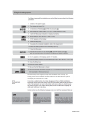
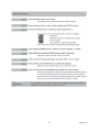
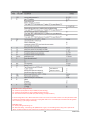
1
Q - Series Boiler
Troubleshooting Manual
WARNING
There are a number of live tests that are required when fault finding this product. Extreme care should be used
at all times to avoid contact with energized components inside the product.
You MUST be a qualified service person before proceeding with these test instructions.
Before checking resistance readings, turn off power source to unit and then isolate each item to be checked
from the circuit by unplugging it.
When setting gas pressures on one of these units, please check the complete model number you are troubleshooting. Gas pressures and dip switches can vary among models. Always check the rating plate for complete
information and follow directions.
CAUTION
Label all wires prior to disconnection when
servicing controls. Wiring errors can cause
improper and dangerous operation.
If any of the original wire as supplied with the appliance must
be replaced, it must be replaced with type 18 AWG wire or its
equivalent.
1
008082013GW
Table of Contents
Code Numbers
Page #
Boiler Description …………………………………………………………………………………………………………………………. 4
Error indication (Short reference) ………………………………………………………………………………………………... 5
BL 01 …………………………………………………………………………………………………………………………………………….. 6
BL 05 …………………………………………………………………………………………………………………………………………….. 7
BL 11 …………………………………………………………………………………………………………………………………………….. 8
BL 12 …………………………………………………………………………………………………………………………………………….. 9
BL 60 …………………………………………………………………………………………………………………………………………….. 10
BL 67 …………………………………………………………………………………………………………………………………………….. 11
BL 80 …………………………………………………………………………………………………………………………………………….. 12
BL 81 …………………………………………………………………………………………………………………………………………….. 13
BL 82 …………………………………………………………………………………………………………………………………………….. 14
BL 84 …………………………………………………………………………………………………………………………………………..… 15
BL 85 …………………………………………………………………………………………………………………………………………….. 16
BL 86 …………………………………………………………………………………………………………………………………………..… 17
E 00 ………………………………………………………………………………………………………………………………………………. 18
E 01 ………………………………………………………………………………………………………………………………………………. 19
E 02 …………………………………………………………………………………………………………………………………………….… 20
E 03 …………………………………………………………………………………………………………………………………………….… 21
E 04 …………………………………………………………………………………………………………………………………………….… 22
E 05 …………………………………………………………………………………………………………………………………………….… 23
E 07 …………………………………………………………………………………………………………………………………………….… 24
E 11 …………………………………………………………………………………………………………………………………………….… 25
E 12 …………………………………………………………………………………………………………………………………………….… 26
E 13 …………………………………………………………………………………………………………………………………………….… 27
E 14 …………………………………………………………………………………………………………………………………………….… 28
E 18 …………………………………………………………………………………………………………………………………………….… 29
E 19 …………………………………………………………………………………………………………………………………………….… 30
E 24 …………………………………………………………………………………………………………………………………………….… 31
E 26 …………………………………………………………………………………………………………………………………………….… 32
E 28 …………………………………………………………………………………………………………………………………………….… 33
E 29 …………………………………………………………………………………………………………………………………………….… 34
E 31 ……..……………………………………………………………………………………………………………………………………….. 35
2
008082013GW
E 32 ….…………..……………………………………………………………………………………………………………………………… 36
E 36 ....…..……………………………………………………………………………………………………………………………………… 37
E 37 …..…………….………………………………………………………..……………………………………………………………….... 38
E 41 …………………………………………………………..…………………………………………………………………………..……… 39
E 42 …………………………………………………………………………………………………………………………………………..….. 40
E 44 ………………………………………………………………………………………………………………………………………………. 41
E 68 ………………………………………………………………………………………………………………………………………………. 42
E 69 ………………………………………………………………………………………………………………………………………………. 43
E 80 ………………………………………………………………………………………………………………………………………………. 44
E 115 …………………………………………………………………………………………………………………………………………….. 45
Fuse …………………………………………………………………………………………………………………………………………….… 46
Central heating but no domestic hot water…………………………………………………………………………………… 47
Hot water but no central heating …………………………………………………………………………………………….…... 47
Central heating installation gets hot without being requested ……………………………………………….…... 47
Insufficient quantity of hot water …………………………………………………………………………………………….…... 48
Temperature drop of the DHW (Combi) ……………………………………………………………………………………….. 48
Radiators do not get hot enough or warming up takes too long …………………………………………………... 48
Checking the 02 …………………………………………………………………………………………………………………………….. 49
Boiler Controls ………………………………………………………………………………………...…………………………………... 50
Explanation of the function buttons ……………………………………………………………………………………..…….… 51
Starting up – filling and de-aerating the boiler & Water Requirements….………………………………….….. 52
Freeze Protection………………………………………………………………………………………………………………………….. 53
Filling the heating system ………………………………………………………………………………………………………..…... 54
Altering adjustments ……………………………………………………………………………………………………………………. 55
PARAMETER mode ………………………………………………………………………………………………………………………. 56
Information, Service and Error Modes …………………………………………………………………………………………. 57
Activating factory setting (Green button function) ………………………………………………………………………. 58
Isolating the boiler ……………………………………………………………………………………………………………………..….59
Reset service interval counter ……………………………………………………………………………………………………… 60
© 2013 Rinnai America Corporation • 103 International Drive, Peachtree City, GA 30269
Toll-Free:1-800621-9419 • Phone: 678-829-1700 • www.rinnai.us
Rinnai is continually updating and improving products; therefore, specifications are subject to change without
prior notice. Local, state, provincial and federal codes must be adhered to prior to and upon installation.
3
008082013GW
4
008082013GW
Parts of the Boiler
5
008082013GW
Block and Errors - Error indication (short reference)
A detected error is indicated on the display by means of a blocking or error messages. A distinction should be made between
these two messages due to the fact that a blocking code can be of a temporary nature, however, error messages are fixed
“lockouts” or hard lockouts. The control will try its utmost to prevent a lockout and will temporary switch off the unit by blocking it,
below is a list of some messages the unit will display.
Blocks: bL with a number in the last two positions indicates the type of blocking code.
bL 01
bL 05
bL 60
bL 67
Block 01:
Block 05:
Block 60:
Block 67:
External safety contact cut off.
Outdoor reset sensor not connected.
Incorrect parameter setting of the minimum or maximum power (Btu) of boiler.
A ∆T has been detected between flow and the return sensor whereas the burner is not in operation. After the
∆T has disappeared the block will clear itself.
bL 85 Block 85: The control has not detected water flow. The venting cycle (pro-purge) cycle has started.
If during this cycle water flow is detected, the pro-purge cycle stops, the burner will then fire up.
Error: E with a number in the last two positions indicates the type of error code.
E
E
E
E
E
E
E
E
00
02
04
05
12
18
19
28
Error 00:
Error 02:
Error 04:
Error 05:
Error 12:
Error 18:
Error 19:
Error 28:
Poor flame forming.
No flame forming.
Adjustment or error due to voltage interruption.
Adjustment.
High limit stat.
Maximum flow temperature exceeded.
Maximum return water temperature exceeded.
Fan revolutions not being measured by control board. Flame present when burner is off, electrical interference, poor
ground, and flame sensing wire disconnected during off cycle.
E 69 Error 69: No or incorrect display.
FUSE FUSE:
24 V fuse defective or blown.
Information displayed in “Tech Readout Mode”. To enter this
mode press and hold the “STEP” button for 5 seconds.
NOTE; if the unit appears to be fine but doesn’t run
and no error code is displayed check;
a.
Operation Indication
0 - No heat demand
1 - Fan pre/post purge
2 - Ignition phase
3 - Burner active on central heating
4 - Burner active on DHW
5 - Fan check
6 - Burner off when either DHW or room thermostat is calling *
(See note 2 below).
7- Pump overrun phase for central heating
8- Pump overrun phase for hot water
9 - Burner off because of too high flow temperature
A - Automatic de-aeration program
F – Fan test still activated in Service mode
H Burner test still activated in Service mode
b.
That the desired programming is on; set to
either Central Heating and/or Domestic Hot
Water.
The unit is not in the Showroom Mode
______________________________________
Explanation of T Sensors:
T1- Supply sensor - Water leaving heat exchanger
mounts in flow of water.
T2 - Return water sensor, surface mounted.
T3 - Domestic hot water flow sensor,. Q175C uses
a surface mount sensor. Q models with optional 3way valve use a sensor designed to be used in a
well. (QP uses a well)
*Note 2; (E Boiler) a continuous code 6 can mean there is a small hot
water leak triggering the plate heat exchanger sensor to call continually
for DHW in turn locking out space heating in DHW priority. Switch PARA
36 to 20 (flow switch only) and then repair leak.
6
T4 – Outdoor reset sensor, mounted outside
building.
T5 - Flue gas sensor - Optional sensor not included
with boiler.
008082013GW
Rectify error by determining which external
contact is open. If external contacts are not being
used place jumper across terminals 24 & 25
The 120 volt external pump is for
E and QP model boilers
͢
If multiple boiler safeties are to be wired in series check with your local inspector or the local or State
codes to see if this is allowed in your area before proceeding. NEVER wire boiler safeties in parallel.
Refer to wiring diagram in the boiler manual. Trace connections 24 and 25 above back to the MCBA.
These will be located on Plug X5 on the MCBA on pins 2 and 6.
7
008082013GW
BL 05
Outdoor sensor contact
open (not connected)
Rectify error by determining if outdoor sensor
is faulty, wiring to senor is broken or damaged
or if the connection at terminal 18/19 on main
control board is properly connected.
8
008082013GW
BL 11
Maximum average ΔT of T1 supply
sensor and T2 return sensor for central
heating is repeatedly exceeded.
Operation is normally possible for the hot water
supply during the block. The pump continues to
operate at minimum capacity during the block.
Rectify Issue,
Check following
1.
2.
3.
4.
5.
Check flow through the heating system.
Possible causes: radiator shut off valves closed, blocked water filter.
Verify proper installation of the boiler plumbing, connections and all components.
Check minimum and maximum temperature difference in Parameter step 46 and 47.
Activated room sensor (RS100) in non leading room (closed thermostatic radiator
valves?) Check pump height. Should this be check pump head? Do not understand
9
008082013GW
BL 12
Maximum average ΔT of supply
sensor and return sensor for hot
water is repeatedly exceeded.
Operation is normally possible for the central
heating installation during the block. The pump
continues to operate at minimum capacity during
Rectify Issue,
Check following
1.
2.
3.
4.
Check flow through the boiler and DHW tank.
Possible causes: radiator shut off valves closed, blocked water filter, restriction in DHW tank to high.
Verify proper installation of the boiler plumbing, connections and all components.
Ensure 3 way valve is functioning properly and is not clogged or full of pollution.
10
008082013GW
NOTE; in order to reset all parameters in your boiler back to factory defaults follow the “Activating Factory Settings”
(Green button function) instructions found in your owner’s manual. CUATION: All parameters you adjusted will now
have to be reprogrammed if the bL60 code clears up. If after resetting the boiler the bL60 still appears, you will need to
replace the sub-PC board and reprogram the MCBA. The sub PC board must be from a conversation kit for the same gas
type as your boiler.
If conversion parts are not locally accessible contact Rinnai Tech Support for assistance. These parameters cannot be
accessed in the field and may require special instructions in an emergency situation.
11
008082013GW
A temperature
difference
has
been
detected
A temperature
difference
has
been
detected
between
the
supply
T1and
sensor
andsensor
the return
between
the
supply
return
whileT2
sensor
while the
burner
is not in After
operation.
the burner
is not
in operation.
the After
the
average
has
disappeared,
the
blocking
average
ΔTΔT
has
disappeared,
the
block
will
code will go away.
disappear.
Check the supply T1 sensor and the return T2
sensor for the proper resistance valve. Replace if
found to be defective.
T2 Sensor
T1 Sensor
12
008082013GW
Inspect vent system and all air passages
ways for blockage
212˚F is the default temperature setting for
parameter 84. Verify to see if the temperature
setting for this parameter is set higher than
the default. If so, inspect vent system for
blockage.
T5 sensor is registering too high of a
temperature. This error can only occur if
the optional T5 sensor is was purchased
and installed on the boiler.
This is the location of the T5 sensor if installed.
If the red tab is in place this sensor was never
installed, which means the circuit has
somehow been jumped out. Contact Rinnai
tech support for assist if you get the bL80
without the T5 sensor being installed.
13
008082013GW
Explanation: The bL81 can be triggered if the flue gas plug has gotten wet and then dried out. (MCBA sees resistance when wet and
then sees no resistance when dry) This tricks the MCBA into thinking that a flue gas sensor was installed and then removed in which
the bL 81 is triggered. Moisture can come from a clog, broken or dry condensate trap. Moisture can be from a leaking concentric
vent pipe or from driving rain during extreme weather.
Methods to rectify:
A.
ORDER AND INSTALL A FLUE GAS SENSOR (This may not be possible in cold weather when boiler must operate
immediately, if shipping the part is required.
B.
CHANGE PARA 80 TO 20 AND INSTALL LOW VOLTAGE JUMPER ON FLUE GAS PLUG - (plug located on upper left hand side
of the heat exchanger in the harness) (PARA 20 setting causes the MCBA to look for an open/ close circuit and ignores any
variable resistance values like moisture or a thermistor.
C.
INSTALL A 10K OHM RESISTOR ACROSS FLUE GAS TERMINALS. This will make the MCBA think that the flue gas is at a safe
temperature level (90 F)
14
008082013GW
Flue sensor or thermostat contact open
15
008082013GW
This can occur on a Q Boiler when the factory
jumper on the flue gas sensor is loose or has
fallen out.
212˚F is the default temperature setting for
parameter 84. Verify to see if the temperature
setting for this parameter is set higher than
the default. If so, inspect vent system for
blockage.
16
008082013GW
Check the installation for the presence of air.
If there is a secondary pump installed and it
is not hydraulically separated, it could cause
a loss of pressure difference.
AIR: if boiler, inner boiler piping, or Low Loss
Header has a large air bubble in it the
pressure sensor will not see the pressure
spike that the pump generates when it starts.
The pressure spike is what tells the MCBA that
the pump has started.
The air bubble will absorb that spike. Bleed all
air from the system.
Check to ensure the pump is functioning and/or water
pressure sensor is working properly.
If an additional expansion tank is placed in the
system alongside an E-boiler that tank can
absorb the pump pressure spike as well. You
may need to isolate that tank to see if this
corrects the issue with BL 85.
Ensure water pressure sensor is not clogged or defective.
Inspect water filter for debris.
Check pump for proper operation and flow rates.
Check for proper wiring of pump.
Check for use of balancing valves.
An expansion that is not charged properly can
cause the pump’s pressure spike not to be
seen by the sensor causing a BL85.
Expansion tank pressure should be air charged
to match whatever water fill pressure that is
chosen for the closed loop. (Always above
14.5 psi)
Expansion tanks must be air charged only
when there is no water pressure on the wet
side of the diaphragm or the tank is removed
from the system. Once charged to the correct
air pressure it may be placed into the system
and the water fill pressure now may be set to
match the new tank pressure.
17
008082013GW
The frequency of the power supply deviates more
than + or - 1.5 Hz.
If using a back-up generator ensure it is
properly grounded and providing a clean
steady voltage and sign wave of 59.3 to 60.8
Hz.
18
008082013GW
Boiler has not been
burning but an
ionization flow
(flame) has been
detected.
Check whether the ionization cable and/or the electrode
are responsible for a short circuit. Remove the plugs from
the ionization cable connected to the control unit and to
the electrode. Now using a ohm meter take a
measurement between the ionization connection and the
ground. Now refit it part by part until a short circuit takes
place.
NOTE: Inadvertently unplugging the ionization
cable or spark igniter wire while the boiler is
not firing can trigger the E00 code.
19
008082013GW
E 01
24 volt short circuit
Remove all 24 volt connectors, such as: fan, pump, any three port valve and the 24 volt plug to the connecting
block. Check for a short circuit in the disconnected components. Next; switch on power to the control board with all
the 24 volt components disconnected. Reconnect the components one at a time, if code E 01 appears when you
plug up a component, that component has a short circuit. Rectify any short circuits or replace defective component
causing short circuit.
20
008082013GW
Ignition Failure Issue
Flame Failure Issue
Ionization flow,
ionization cable or
02 setting
Due to insufficient
ionization the burner
has shut down after
ignition
The minimum ionization current
should be 4 micro amps (Check
INFO step 48, the O2 should be a
minimum of 4.4% for NG or 4.8%
for LP.
Note: if ionization is lost while the flame is
burning no E02 will occur - unit will attempt to
relight 6 times. E02 only occurs after 6 failed
attempts for re-ignition.
21
Propane gas with low BTU value or a brand
new tank that may contain something other
008082013GW
than pure propane may cause
E02. Check
against a good known source of gas.
Control unit error - Connector not plugged into the gas valve
or defect in the wiring harness to the gas valve.
Check for 24 volts DC at gas valve.
In some cases an E03 is caused from a loose
connection on wires to the gas valve. This
faulty connection may be in the Molex plug
(X5) on the MCBA. Examine plug closely for
bayonets that may have backed out of plastic
casing.
Check across terminals 4 and 5 at plug X5 on the main
control board. See wiring diagram for your boiler for
terminal locations
22
008082013GW
The boiler automatically indicates this message if
during
an error
read-out the
electrical
to if
The boiler
automatically
indicates
thispower
message
the
boiler
shut read-out
off. Afterthe
theelectrical
power is power
once again
during
aniserror
to
switched
on,
theoff.
error
causing
the interference
the boiler
is ifshut
After
the power
is once is
no
longer
present,
message
is given the
again
switched
on,this
if the
error causing
interference is no longer present, this message is
23
008082013GW
Check ribbon cable between the control
unit and the display board. A loose
connection between these two points can
cause communication issues between
boards leading to an error code. If ribbon
cable is loose or damaged, repair or
replace cable as needed.
If error persist
after reset
Software error control unit, replace control unit. Remove
the E-Prom from the defective control unit and place it
onto the new control. The controller will automatically
load the program into the new control unit.
24
008082013GW
E 06
Control unit error
Moisture on the PC board, check for
leaks on or in the boiler. Replace PC
board if needed.
25
008082013GW
Replace the control unit. The controller will
automatically load the program into the new
control unit.
26
008082013GW
27
008082013GW
VERY RARE THAT AIR IS AT FAULT. If air is
present it will be indicated by a gurgling
noise. Normally when an airlock is
present a BL85 will be indicated
Clean the pump and/or filter when necessary.
Flush complete system
28
008082013GW
Replace the control unit. The controller will
automatically load the program into the new
control unit.
29
008082013GW
-
- T3 flow sensor ground connection
T3 flow sensor failure or controller failure
To determine flow temperatures for T3 use the chart to the
left for proper resistance values for a set temperature.
When no discrepancies are found on the sensors it
may be a leakage of current coming in from an end
switch or pump relay box connected to terms 22 and
23. Install isolating relay on 22 and 23 or replace
faulty end switch / or pump relay box connected to
22 and 23 (NO VOLTAGE MUST COME INTO 22 and
Thermostat indirect tank failure – replace
thermostat by T3 (with cable) for indirect tank
T3 Sensor is located behind the condensate
trap on the E series boiler; this will look different
on Q and QP boilers. This is a close up of the
T3 sensor with the condensate trap removed.
30
008082013GW
Signal maximum flow water temperature exceeded
(T1 ˃ 212⁰F).
Actual
flow flow
Check actual
temperature
temperatureshould be
verified before T1 is
determined.
T1 Sensor
31
008082013GW
Signal maximum return water temperature
exceeded (T2 ˃ 212⁰F).
T2 Sensor located
under T1 sensor
32
008082013GW
T1 and T2 (swapped).
T2 temperature is measured to be higher than T1. Check
resistance value of T1 and T2 (See resistance chart under error
19 for resistance values. Replace T! and/or T2 if found to be
defective.
T1 Pressure Transducer
T2 sensor
33
008082013GW
Replace MCBA board, main board.
34
008082013GW
No feedback signal from fan motor.
Check the wiring harness to the fan motor and control
unit. Check power supply to motor during combustion
process, should be 24 volts DC.
Fan motor wiring harness
constant 24 volts DC.
Tachometer cable
Feedback signal
35
008082013GW
There is a negative pressure on vent system (Pressure
difference). Check to see if fan motor is spinning.
Vent system and air intake must be installed
according to the installation instructions.
The E29 is triggered immediately after fan check code 5 during the starting sequence. If during fan
check 5 the fan remains spinning more than 150 rpms an E29 will occur.
Causes:
Wind driving into a concentric terminal. Replace with 90 degree terminal or for best results
use a roof terminal.
-
Venting running a long distance in a cold attic space causing a thermo syphon after fan check.
Use room air for combustion if conforming to NFPA 111 guidelines for room air or use
concentric terminal directly through the roof.
36
008082013GW
Internal shut down of supply sensor T1.
T1 sensor short circuit is indicated by low ohm reading.
Replace defective sensor, see resistance values in chart
on E 18 above.
T1 Sensor
37
008082013GW
Shut down of return sensor T2,
T2 sensor short circuit is indicated by low ohm
reading. Replace defective sensor. Refer to
resistance chart on E 19 above.
38
008082013GW
Contact for supply sensor T1 open,
indicated by infinite ohm reading.
T1 Sensor
39
008082013GW
Contact for the return sensor T2 open,
indicated by infinite ohm reading.
Remove the plug from the flow sensor
as a result of which error 32 occurs.
T2 Sensor
40
008082013GW
41
008082013GW
42
008082013GW
Electrical short circuit, possible water damage to
MCBA, main board
43
008082013GW
If this error is displayed, there is no software on the
MCBA or display. A RINNAI conversion kit specific for
the boiler model and fuel type must be installed.
Follow the conversion kit instructions to load the
software to the MCBA.
44
008082013GW
Ribbon cable problem.
Q-Series ribbon cable problem or defective key pad.
Replace ribbon cable
45
008082013GW
T5 sensor is reading too high of a flue gas temperature. (Adjust
parameter 84 – default 212 ⁰F) See location of T5 sensor below. If red
cap is installed, T5 sensor is not being used.
Moisture on the flue gas sensor wires or
terminals could cause a false temperature
reading.
T5 Senor, if
installed
46
008082013GW
E 115
Replace MCBA board
47
008082013GW
Check fuse mounted on PC board to see if it blown. In addition, check
transformer output and wiring harness for transformer to ensure it is
plugged in properly.
This is the low voltage fuse that is located
directly next to the PCB board transformer.
The OEM fuse has colored stripes; the spare
fuse located on control cover is a clear glass.
Please verify the amp rating (4 amp) on the
metal rim of the fuse before installing it. It
must be the same amperage as the fuse being
replaced.
48
008082013GW
Additional Troubleshooting Instructions
49
008082013GW
50
008082013GW
Checking the O2 Setting
51
008082013GW
Boiler Controls
Burner off while there is a demand for central heat of DHW.
Burner off when room thermostat is demanding or burner off when DHW is calling.
52
008082013GW
Explanation of the function buttons
This LED should never be left on.
Pressing R or the reset button for more than 5 seconds will activate a 17 minute de-aeration
cycle.
53
008082013GW
Starting up: Filling and de-aerating the boiler and installation
Requirements of the water system
54
008082013GW
55
008082013GW
Filling the heating system
Note: You must have either a hot water or heat demand to activate de-aeration
Check the water pressure regularly and top off the installation when necessary. The
working pressure of the installation should be between 16 and 18 PSI when the system is
cold. Adjust your auto-feed to 16 – 18 PSI.
56
008082013GW
Altering adjustments
57
008082013GW
See additional
definitions below
PARA 36 E Combi. setting definitions
00 = activation by temperature drop for DHW (no plate warming)
10 = activation by temperature drop for DHW (plus plate warming)
20 = flow switch activation only DHW. (No plate warming/ no temp actuation)
In either setting above - 00 or 10 the Flow switch is still in the circuit and if it sticks "closed" it can keep the boiler locked
in DHW and code 6 with appear on the screen. Unplug flow switch as it is not needed. (Do not waste time taking switch
out and cleaning it, just unplug it electrically)
PARA 36 Q combi
01 = factory setting-load sharing "on"
00 = Alternate setting - Load sharing "off" (MCBA thinks a "grey" non-modulating valve is being used in place of the
"Black" modulating valve) All other combinations are NOT to be used on Q-combi boilers)
58
008082013GW
59
008082013GW
Activating factory settings (Green button function)
60
008082013GW
Isolating the boiler
61
008082013GW
Reset service interval counter
62
008082013GW