1
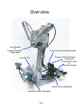
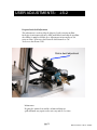
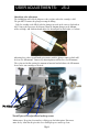
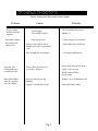
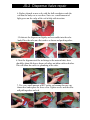
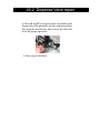
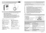
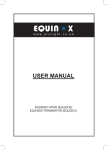
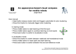
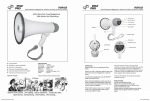
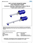
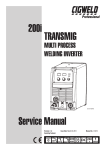
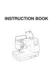
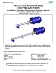
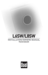
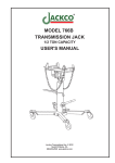
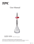
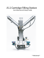
JS-2 Cartridge Filling Station
User Manual and Setup Guide
FS All Rights Reserved 2006
Pantent pending
CONTENTS:
JS-2 Filling Station
Page
Overview....................................................1 & 2
Introduction...................................................
3
Setup............................................................
4
User Adjustments & Maintenance..............5 & 6
Troubleshooting............................................
7
Parts List...........................................................8
Overview
Drop-down Cylinder
Snuff-back
Dispense Valve
Head down lockout switch
Dispense Head
Part placement switch
Frame Upright
Air Regulator
Start-fill Palm Button
E-Stop Palm Button
Nesting Die
Shutoff Pin
Pg.1
Overview
Nose Retainer
&
Support Assembly
(Adjustable)
Dispense Valve Delay (Adjustable)
Dispense Head Dwell Timer
(Adjustable)
Control Valve Stack
&
Manual Overrides
Cartridge Die
Die Retainer
Lockout Timer (Adjustable)
Shutoff Pin Valve (Adjustable)
Pg. 2
INTRODUCTION;
JS-2
The JS-2 semi-automatic Cartridge Filling Station has been designed
for production runs of low- to medium. The design allows for most all
cartridge sizes and ratios. Depending on the viscosity of the material
and the delivery system used (pumps/pressure vessel), the JS-2 can fill
two ratio-pak 600ml cartridges in 10sec. with no drip and without
the need to insert the plunger into a full cartridge.
The JS-2 comes with two high-volume snuff back dispense valves
with user replaceable seals. Your delivery system will hook directly
to these valves via hose connections.
The operation is simple: with the plungers inserted completely into the
cartridge set, the operator places cartridge set into the fixture (over the
top of the shutoff pins) and depresses the start-fill palm button. The dispense
head moves down and the dispense valves open, filling each cartridge
simultaneously.
As the material fills the cartridge the plungers are forced down until
they contact the shutoff pins closing the dispense valves. When both
cartridges are full, the dispense head retracts and operator removes the
cartridge set and inserts the nose plugs.
CAUTION:
Hazards exist when operating any automated or semi-automated equipment.
Any person operating this equipment should wear safety glasses and be familiar
with all safety aspects of operation. Adjustments and setup procedures should be followed
as directions show and be carried out by a qualified person. Operating in disregard of this
information could result in injury or unnecessary chemical spill.
Pg. 3
SET-UP INSTRUCTIONS:
JS-2
Following these instructions will assure you get set up and running with
minimal problems. Please - before calling for tech support, go through
the trouble-shooting sequence. Most problems can be remedied there.
Step 1. Make all the hose connections and connect air supply to the filler.
Step 2. Adjust the valve shutoff pins for your cartridge sets.
(see: setting fill level via valve shutoff pins, pg.6) Check that the head is
aligned with the cartridge nose. If needed, adjust nose retainer.
Step 3. With the air supply connected, turn the regulator pressure
to 80 psi.
Step 4. This is a dry run only; DO NOT turn on the material pump.
Place a cartridge set into the fixture and depress the green start-fill palm
button for 3sec. The dispense head will move down and seat into
the cartridge nose and you will hear the dispense valves open after a
short delay. (NOTE: check that the rubber nozzle seal is seated firmly on the
cartridge nose.)
Now push the RED E-stop plam button and you will hear the dispense
valves close. Hold the E-Stop down for 3sec. and the dispense head retracts.
If all operations are working correctly go to step 5. If not, go to troubleshooting table Pg.7.
Step 5. Purge the system of air: DO NOT turn on the material pumps.
Place a container under the dispense head; using a small probe, push the
manual overide button for "valve A open."
You will hear the dispense valve open. In this position you can now purge the
lines of any air.
Pg.4
p›˜Šˆ@†•”š„Œ”ˆ˜
dŒ™–ˆ”™ˆ@v„’œˆ@•œˆ˜M˜Œ‡ˆ
@@@H@bM™Œ‡ˆ@™‹•ž”@‹ˆ˜ˆI
Step 6. Slowly bring pump A pressure up until you get material with
no air from the dispense head; then push the red stop button to close the valve.
Turn the pump pressure back to zero. Repeat this procedure for pump B.
Step 7. Be sure the shutoff pins are in place and working freely.
Place a cartridge set into the fixture (over top of pins) and depress
the green palm button for 3sec. The head moves down and the valves open.
Now turn pump A pressure up until you achieve the fill speed desired.
Repeat this procedure for pump B. After B side completes fill cycle, the
dispense head will retract. Note: if head does not retract automatically,
manually raise the dispense head by holding the red E-stop button for 3sec.
Note: Always start pumps slowly so as not to surge the material
into the cartridge set for safety during setup.
Setup is complete.
PG.4-1
USER ADJUSTMENTS:
JS-2
Dispense head dwell adjustment
This adjustment is used to delay the dispense head retracting to allow
for heavy viscosity materials to be fullly snuffed back and stop the overflow
after filling is completed. Make these adjustments in increments of 1/8
turns at a time. To increase dwell turn the dial shown here CW.
To decrease dwell turn CCW.
.
Dial-in dwell adjustment
Maintenance
Keeping the station clean and free of material drips or
spills will make any repairs to the unit easy, and use less time.
pg. 5
c•”šŒ”›ˆ‡@”ˆŸš@–„Šˆ
USER ADJUSTMENTS:
JS-2
USER ADJUEN-2
Shutoff pin valve adjustment
The shutoff pin valve tells the dispense valves to close when the cartridge is full.
The pin MUST contact the plunger to stop the filling.
Take the cartridge to be filled, with the plunger inserted to the correct depth when
full. Using a ruler, measure the distance from the bottom plunger to the bottom
of the cartridge, add 1/8th inch and adjust the shutoff pins to that height (see below).
Adjusting these valves up will make pin contact with the plunger sooner, which will
decrease the fill amount. Conversely, adjusting down will increase the fill amount.
These pins are for fine tuning the amount of material and to balance the fill amount
between the two cartridges as desired.
Pin Valve Lever
Shutoff pin valve adjustment locking screws
Maintenance: Keep pins clean and use a light grease for lubrication. Pins must
move freely. Also coat the pin valve lever with light grease and keep clean.
Pg. 6
TROUBLE SHOOTING
Please contact your sales rep for further support
Problem
Depress palm
button - nothing
happens.
Head moves down
but no material
is dispensed
Cause
Remedy
No air supply
No cartridge in place
Check regulator has pressure
60-80 p.s.i.
No pump pressure
Check pumps are pressurized
Dipense valve locked closed
Possible material set up around
seals.
Disassemble valve and clean
Valve shutoff pins stuck down
Clean pins and lubricate
Dispense valve
leaking from nose
or won't shut off
Nose seal has debris in it or
needs to be changed.
Material overflows
from the cartridge
nose after filling.
Air in the material causing
bubbling.
Dispense head dwell too short
Disassemble valve and clean or
replace seal as nessary.
Install a material-filter
on the pump.
Pg.7
Remove excess air from material
Adjust dwell time longer
PARTS LIST:
Description
JS-2
Part #
QTY.
Valve Stack....................PN. #155........................1
Dispense Valve..............PN.# .875-2.................. 2
Dispense valve seal.......PN.# poly-875................4
Shutoff pin valve...........PN.# 31p........................2
Dispense safety valve....PN.# 31p........................1
Dwell timer.....................PN.# dly-.01-30..............1
Delay timer....................PN# dly-.01-3.................1
Pin lever.........................PN.# lev-01..................2
Shutoff pin......................PN.# P-002....................2
Dispense head...............PN.# DH-0-125..............1
Palm button...................PN# 1111A-038...............2
Part placement switch....PN# PCX-121................1
Head down switch...........PN# 31P........................1
Lockout timer..................PN# LTY.03-6.................1
Pg. 8
JS-2 Dispense Valve repair
1. Remove valve from dispense head and place in work vise then
remove the three screws that hold the body togeather as shown here.
2. Seperate the nose from the body and the body from the cylinder
mount by pulling apart.
3. Remove the seals with a dull screw driver and clean all parts .
JS-2 Dispense Valve repair
4. Replace cleaned or new seals, with the dull screwdriver work the
seal into the body seat as seen here. Note: use a small amount of
light grease on the eadge of the seal to help with insertion.
5. Lubricate the dispense rod lightly and reassemble into the valve
body. Place the valve on a flat surface as shown and push togeather.
6. Note the aligenment of the air fittings to the material inlet, these
should be about 90 degrees from each other not inline with each other.
This will allow for correct re-plumbing of the valve.
7. Use a very small amount of RTV gasket seal aroung the nose cap
shown here and replace the three screw. Tighten screws and the valve
will pull togeather and seal.
JS-2 Dispense Valve repair
8. Clean off any RTV and grease then reassemble to the
dispense head. Re-plumb the air lines and material line,
then using the manual over rides activate the valve and
check for proper operation.
9. Run setup as discribed