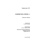
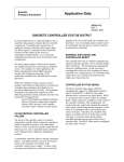
1
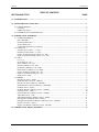
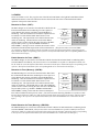
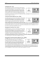
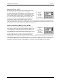
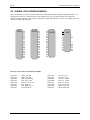
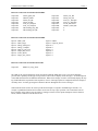
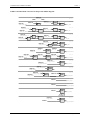
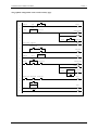
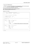
Siemens Energy & Automation CONFIGURATION GUIDE CGiLL-1 Rev: 2 September 2005 Supersedes Rev 1 Ladder Logic %RecrPmp_Stop_PB %Close_Recirc 35 %Close_Recirc %RecrPmp_Srt_PB 36 Gas_Start_Abort 37 Reset_MFT Gas_OK Start_Gas %Start_Gas_PB 38 Gas_On 39 Start_Gas Igniter_Proven %Open_Gas_Valves %Stop_Gas_PB 40 Gas_Delay 0.03333 TON 41 %Gas_V1_NotOpen 42 %Stop_Gas_PB %Gas_V2_NotOpen Gas_Start_Abort 43 %Vent_NotClosed 44 %Open_Gas_Valves Gas_Start_Abort %Burner_Flame Gas_On 45 Op_Requirements 46 ULC_Loop_Error 47 %Master_Abort_PB %MFT 48 ULC_Loop_Error 49 %System_Alarm CGiLL-1 CONTENTS TABLE OF CONTENTS SECTION AND TITLE PAGE 1.0 INTRODUCTION ................................................................................................................................................1 2.0 CONFIGURATION OVERVIEW......................................................................................................................1 2.1 CONFIGURATION .........................................................................................................................................2 Loop Tags .......................................................................................................................................................2 Ladder Logic Pages.........................................................................................................................................2 2.2 LADDER LOGIC CONFIGURATION...........................................................................................................2 3.0 LADDER LOGIC ELEMENTS..........................................................................................................................5 3.1 LADDER ELEMENTS...................................................................................................................................5 Power Rail (PR) |............................................................................................................................................5 Horizontal Shunt (HS) -----.............................................................................................................................5 Vertical Shunt (VS) | .......................................................................................................................................5 Connections By Reference <reference>..........................................................................................................5 3.2 CONTACTS.....................................................................................................................................................6 Normally Open Contact --| |-- NOC ................................................................................................................6 Normally Closed Contact --|\|-- NCC..............................................................................................................6 Positive Transition Sensing Contact --|P|-- PTC .............................................................................................6 Negative Transition Sensing Contact --|N|-- NTC ..........................................................................................6 3.3 COILS ..............................................................................................................................................................7 Coil --(C)-- ......................................................................................................................................................7 Set (Latch) Coil --(S)--....................................................................................................................................7 Reset (Unlatch) Coil --(R)-- ............................................................................................................................7 Retentive (Memory) Coil --(M)--....................................................................................................................7 Set Retentive (Memory) Coil --(SM)-- ...........................................................................................................7 Reset Retentive (Memory) Coil --(RM)-- .......................................................................................................8 Positive Transition-Sensing Coil --(P)-- .........................................................................................................8 Negative Transition-Sensing Coil --(N)-- .......................................................................................................8 Negated Coil --(NG)--.....................................................................................................................................8 3.4 TIMERS ...........................................................................................................................................................9 Retentive On Timer --(ROT)-- ........................................................................................................................9 Enable Retentive On Timer --(EROT)-- .........................................................................................................9 Retentive On Timer (Memory) --(ROTM)-- ...................................................................................................9 Enable Retentive On Timer (Memory) --(EROTM)--.....................................................................................9 On-Delay Timer --(TON)-- ...........................................................................................................................10 On-Delay Retentive (Memory) Timer --(TONM)-- ......................................................................................10 Off-Delay Timer --(TOF)-- ...........................................................................................................................10 Off-Delay Retentive (Memory) Timer --(TOFM)-- ......................................................................................10 Timed Pulse Timer --(TP)-- ..........................................................................................................................11 Timed Pulse Retentive (Memory) Timer --(TPM)-- .....................................................................................11 Retriggerable Timed Pulse Timer --(RTP)-- .................................................................................................11 Retriggerable Timed Pulse Retentive (Memory) Timer --(RTPM)-- ............................................................11 Repeat Cycle Timer --(RCT)-- ......................................................................................................................12 Repeat Cycle Retentive (Memory) Timer --(RCTM)-- .................................................................................12 4.0 LADDER LOGIC DESIGN EXAMPLE..........................................................................................................13 September 2005 i CONTENTS CGiLL-1 Changes for Rev 2, September 2005 • There were no technical changes. • References to Moore Products, Co. were replaced with Siemens Energy & Automation, Inc. • Disclaimer text updated. • Add Product Support section. Procidia, i|config, and i|station are trademarks of Siemens Energy & Automation, Inc. Other trademarks are the property of their respective owners. All product designations may be trademarks or product names of Siemens Energy & Automation, Inc. or other supplier companies whose use by third parties for their own purposes could violate the rights of the owners. Siemens Energy & Automation, Inc. assumes no liability for errors or omissions in this document or for the application and use of information in this document. The information herein is subject to change without notice. Procedures in this document have been reviewed for compliance with applicable approval agency requirements and are considered sound practice. Neither Siemens Energy & Automation, Inc. nor these agencies are responsible for repairs made by the user. Copyright © 2005, Siemens Energy & Automation, Inc. ii September 2005 CGiLL-1 INTRODUCTION AND OVERVIEW 1.0 INTRODUCTION This Configuration Guide provides detailed descriptions of Procidia™ ladder logic elements and their implementation. The Procidia Internet Control System (ICS), the Model 353 Process Automation Controller, and the Model 354N Universal Loop Controller represent the next generation in controller technology. Designed to satisfy the needs of both continuous and discrete control applications, these controllers have access to a large library of reusable function blocks that can be applied to a configuration to manage a vast array of process control applications. Depending upon controller model, either a Universal Serial Bus or a LonWorks® fieldbus interface extends the analog and digital I/O of these controllers over a low cost, easy to install twisted pair cable. As a result, applications traditionally requiring a single-loop controller and a PLC can now be accomplished in a single controller. Ladder logic configurations are built using the i|config™ Graphical Configuration Software. Install the software on a Windows®-based personal computer or on an i|station™ Industrial PC. When completed, the configuration is then downloaded to the target controller. Related Literature This manual can be used with: • i|config Graphical Configuration Utility Software Guide SG15939-64 - This manual describes use of the software to create and download a configuration. • Procidia Function Blocks and FCOs Configuration Guide CGiFB-1 - This manual contains a description of each function block and factory configured option provided in controller firmware. • Procidia i|pac™ User’s Manual UMiPAC-1 (and -2) - This manual describes installation of the i|pac and i|o™ hardware and UMiPAC-1 contains CGiFB-1. • Controller User’s Manuals UM353-1 and UM354N-1 - Each manual describes installation of the named controller and it contains the function block and factory configured option details for that controller. Product Support Telephone NORTH AMERICA Fax E-mail Hours of Operation Public Internet Site Repair Service +1 800 569 2132, option 2 for Siemens-Moore brand instruments +1 215 646 3547 [email protected] 8 a.m. to 4:45 p.m. eastern time Monday – Friday (except holidays) www.sea.siemens.com/ia/ +1 215 646 7400 extension 3187 For contact information outside North America, visit the Siemens public Internet site (see the above table for the URL), locate “Customer Support Process Instrumentation,” and click on the Contact Tech Support link to access the Global Support link. 2.0 CONFIGURATION OVERVIEW Controller configuration is the selecting and interconnecting of function blocks from an available list and the entering of appropriate block parameters to implement a specific control strategy. Although configuration affects the entire controller, the controller partitions related control implementations into LOOPS. Each LOOP can contain the function blocks listed in the above manuals. Signals can be connected between function blocks within the LOOP as well as between loops. Also, there are several STATION function blocks that are fixed and available in the STATION menu for setting station related values, such as security. Ladder logic September 2005 1 INTRODUCTION AND OVERVIEW CGiLL-1 status can be displayed using the Operator Display for Discrete Indications and Control (ODD) function block and a logic sequence can be initiated from an Operator Display for PushButtons (ODP) function block. Refer to CGiFB-1 or the controller’s User’s Manual for the list of function blocks and their definitions. Each controller must be configured to perform the desired control strategy. The arrangement of functions and the numerical data required for a particular control circuit are referred to as the controller configuration. A configuration is designed by first arranging the needed function blocks in a fashion similar to that of a P & ID drawing. Parameter and calibration values are determined next and then entered on a Configuration Documentation Form (e.g., CG353-2) and finally into the Graphical Configuration software. 2.1 CONFIGURATION This section provides tips for use while configuring a controller. Most references to controller displays are to those seen on either i|station or a Local Faceplate, Display Assembly faceplate, or Faceplate Display, depending upon controller model. Loop Tags Begin a configuration by laying down all of the loops and assigning loop tag names. A loop tag should be a meaningful name of 6 to 8 characters, although a tag name can be up to 12 characters. The controller will display 8 characters: the last 6 characters in the tag name, a period, and a variable (P, S, V, X, Y, T or “ ”). The entire tag name, when more than 6 characters, can be viewed by pressing the TAG key. For example, a tag of “Primary” is displayed as “rimary.P”. The “.P” indicates that the process variable is shown in the digital display. When the Tag key is pressed, the full tag would scroll “Primary”. To avoid scrolling and show the tag name and variable, condense the tag name. For example, condensing “Primary” to “Prim” would cause the display to read “Prim.P”. A ladder logic loop tag name should be up to 8 characters. While in configuration mode, a maximum of 8 characters can be displayed. The controller distinguishes between analog and digital signals. If you need to convert a digital signal to analog, use the Transfer Switch block (TSW). The inputs do not need to be configured. If you need to convert an analog signal into digital, use a Comparator block (CMP) 1. When creating a large loop configuration, first go into Page view and then lay down all the blocks. This will permit you to quickly organize the blocks in a logical order. Ladder Logic Pages Up to four pages of ladder logic rungs are permitted in the ladder logic loops. In practice, it is best to use only two pages of ladder logic per loop. After the second page, you typically will run out of loop resources. For this reason, it is best to switch to a new loop after two pages of ladder. When configuring ladder logic, it is useful to skip a rung between each rung of ladder created. While debugging the ladder logic, you will probably need to add more contacts or rungs of logic. Having unused rungs makes it easy to add needed rungs. 2.2 LADDER LOGIC CONFIGURATION A summary of the steps involved in assigning names to Ladder Logic elements follows. Each step is then further divided into steps is subsequent paragraphs. 1. Create the loops necessary for the ladder. 2. Enter the discrete inputs to the ladder in the Reference list. 1 For function block details, refer to CGiFB-1, UMiPAC-1, UM353-1, or UM354N-1. 2 September 2005 CGiLL-1 3. Draw the ladder. 4. Name the contacts in the ladder. 5. Name the coils in the ladder. 6. Connect the coils to the discrete outputs. INTRODUCTION AND OVERVIEW Create the loops necessary for the ladder 1. Create a function block loop called “Disc I/O”. 2. In this loop, place all of the I/O blocks that will be used by the ladder, such as DIN's, DID's, DOUT's and DOD blocks. 3. Create a ladder logic loop to construct the ladder. Create the Reference List for the discrete inputs to the ladder 1. Select Reference from the Edit>References menu to get the Edit/Reference dialog box. 2. Left click on the Create button to get the Create/Modify References dialog box. 3. Type in the reference name of the discrete inputs to the ladder, such as “FAN RUNNING” or “FLAME ON”. 4. Now click on the check mark in the box next to ‘Unconfigured’ to configure the input. (Alternatively, click on the name of the loop containing the Discrete I/O in the ladder.) It is now possible to select the loop, block, and output that will be connected to the discrete input. A % symbol will appear in front of the reference name. This indicates that the reference is connected from the ladder to a signal outside the station. A > symbol indicates a connection from the ladder to another loop within the station. No symbol in front of the reference name indicates that it is connected within the ladder only. Draw the ladder 1. Draw the ladder by selecting the New Ladder Logic Element button from the Line Connection Toolbar and selecting the appropriate contacts and coils. 2. Next, select the Line Connection Mode button on the Line Connection Toolbar. The cursor will change to a wire spool that is used to interconnect or "wire" the elements in the ladder. 3. Wire all the elements into the desired ladder logic configuration. Name the contacts on the ladder 1. Name the contacts in the ladder using the wire spool cursor. Right click on the contact name. The set reference dialog box will pop up. 2. For external inputs, select the proper discrete input from the list created earlier. 3. Add to the reference list any contact that comes from a loop within the station. Select the Edit/References button and click on the Create button. The Create/Modify References dialog box will pop up. Name the contact reference and then specify the loop block and output used to provide this discrete input to the ladder. 4. If a contact comes from a coil on the ladder, leave it unconfigured until the coils are named in the next step. September 2005 3 INTRODUCTION AND OVERVIEW CGiLL-1 Name the coils on the ladder 1. To name coils, continue to use the wire spool. Right click on the coil name; usually it will be in the form of DefCoilTagn. 2. The Create/Modify Reference dialog box will pop up with the coil name highlighted. 3. Change the reference name to the appropriate name and click on OK. 4. Go to the next coil and repeat this procedure until all the coils are named. 5. Go back through the ladder and name the unconfigured contacts that come from the coils that were just named. This is done by using the wire spool and right clicking ‘Unconfigured’ above the contact. As before, the Set Reference dialog box pops up and the appropriate coil name may be selected from the references listed by highlighting the appropriate name and clicking on OK. Connect coils to discrete outputs 1. Connect each coil that drives a discrete output, such as START FAN, OPEN GAS SSV's, to a discrete output block. This is accomplished by opening the "Discrete I/O" function block loop with the Line Connection Selected Mode cursor button that is next the wire spool button. 2. Double click on the appropriate discrete block. The Item Attributes dialog box will pop up. 3. Click on the tab for the block selected. 4. Then click on the appropriate input to highlight it. 5. Next, highlight the word Reference in the Connect to box. 6. Then click on the Edit Input button in that box. The Set Reference list will pop up with all the coil names listed. 7. Click on the proper coil name that corresponds to the discrete output channel desired and then click OK. This connects the coil to that discrete output channel. When the coil goes high, the discrete output will go high. 4 September 2005 CGiLL-1 LADDER LOGIC ELEMENTS 3.0 LADDER LOGIC ELEMENTS Logic functions are implemented in a controller using function blocks (Boolean functions). Many users, however, prefer ladder diagrams for developing logic configurations. The graphical configuration utility can be used to configure logic using ladder techniques. This section provides a list of ladder diagram elements, contacts, coils, and timers available for use within the graphical configuration utility. It also describes how they correspond to controller function blocks. A sample ladder logic page with a variety of elements is shown below. %RecrPmp_Stop_PB %Close_Recirc 35 %Close_Recirc %RecrPmp_Srt_PB 36 Gas_Start_Abort 37 Reset_MFT Gas_OK Start_Gas %Start_Gas_PB 38 Gas_On 39 Start_Gas Igniter_Proven %Open_Gas_Valves %Stop_Gas_PB 40 Gas_Delay 0.03333 TON 41 %Gas_V1_NotOpen 42 %Stop_Gas_PB %Gas_V2_NotOpen Gas_Start_Abort 43 %Vent_NotClosed 44 %Open_Gas_Valves Gas_Start_Abort %Burner_Flame Gas_On 45 Op_Requirements 46 ULC_Loop_Error 47 %Master_Abort_PB %MFT 48 ULC_Loop_Error %System_Alarm 49 3.1 LADDER ELEMENTS Power Rail (PR) | This element is on the left of the ladder diagram and is always conducting. Horizontal Shunt (HS) ----This element conducts when the element on the left is conducting and transfers this state to the element on the right. Vertical Shunt (VS) | This element is the inclusive OR of the states of the elements to its left. Connections By Reference <reference> The <reference> is the connection element to other elements within the ladder diagram and to inputs and outputs of function blocks within the loop. September 2005 5 LADDER LOGIC ELEMENTS CGiLL-1 3.2 CONTACTS A contact is a ladder element that copies a state to the element on its right equal to the logical AND of the state of the element on its left with the state of the reference. Normally Open Contact --| |-- NOC The NOC copies the state of the left horizontal shunt to the right <reference> A horizontal shunt, if the state of the contact reference is TRUE. A ANDxx O1 B O1 B Otherwise the state of the right horizontal shunt will be nonNOC conducting. {The NOC is equivalent to a two input AND function block having inputs A <reference> & B and output O1. If the B input is connected to the Power Rail the contact output will equal the <reference> and an actual AND function block is not required.} Normally Closed Contact --|\|-- NCC The NCC copies the state of the left horizontal shunt to the right <reference> horizontal shunt, if the state of the contact reference is FALSE. O1 A A A NOTxx B O1 ANDxx O1 B Otherwise the state of the right horizontal shunt will be nonNCC conducting. {The NCC is equivalent to a two input AND function block having inputs A <reference> & B and output O1 and a NOT function connected to the A input of the AND block.. If the B input is connected to the Power Rail the contact output will equal the output of the NOT function block and an AND function block is not required. } Positive Transition Sensing Contact --|P|-- PTC The PTC copies the state of the left horizontal shunt to the right <reference> A horizontal shunt for one scan cycle, when the state of the contact O1 A A O1 B RTGxx P ANDxx O1 B reference changes from FALSE to TRUE. Otherwise the state of PTC the right horizontal shunt will be non-conducting. {The PTC function is equivalent to a two input AND function block having inputs A <reference> & B and output O1 and a RTG rising edge trigger function connected to the A input. If the B input is connected to the Power Rail the contact output will equal the output of the RTG function block and an AND function block is not required.} Negative Transition Sensing Contact --|N|-- NTC The NTC copies the state of the left horizontal shunt to the right <reference> horizontal shunt for one scan cycle, when the state of the contact A O1 A A O1 B FTGxx ANDxx O1 N B reference changes from TRUE to FALSE. Otherwise the state of NTC the right horizontal shunt will be non-conducting. {The NTC function is equivalent to a two input AND function block having inputs A <reference> & B and output O1 and a FTG falling edge trigger function connected to the A input. If the B input is connected to the Power Rail the contact output will equal the output of the FTG function block and an AND function block is not required.} 6 September 2005 CGiLL-1 LADDER LOGIC ELEMENTS 3.3 COILS Coils copy the state of the left horizontal shunt to the right horizontal shunt without modification and store the state of the left horizontal shunt into a Boolean variable, having a unique user assigned name for use within the graphical ladder diagram. Coil --(C)-The C coil sets the state of the reference to TRUE when the left horizontal shunt is conducting and to FALSE when not conducting. {The coil function is associated with the output state of another function block and assigns a unique reference name within the ladder diagram to this state.} <REFERENCE> O1 O1 C Set (Latch) Coil --(S)-The S coil sets the state of the coil reference TRUE when the left S <reference> S horizontal shunt changes from not conducting to conducting. It will O1 O1 R SRFxx S S remain TRUE, after the left horizontal shunt returns to a not S PU LAST = NO conducting state, until the reference is reset using an R coil assigned to the same reference. During a warm or cold start the reference will be set to FALSE. {The set coil function is equivalent to a SRF function block having input S connected to the left horizontal shunt, the block output O1 associated with the coil reference, and PU LAST set to NO. The left horizontal shunt of the corresponding R coil is connected to the R input. Set is paired with the complementary Reset function. } Reset (Unlatch) Coil --(R)-The R coil resets the state of the coil reference to FALSE when the S O1 <reference> R SRFxx left horizontal shunt changes from not conducting to conducting. It O1 R R R will remain FALSE after the left horizontal shunt returns to a not R PU LAST = NO conducting state, until the reference is set using an S coil assigned to the same reference. During a warm or cold start the reference will be set to FALSE. {The reset coil function is equivalent to a SRF function block having input R connected to the left horizontal shunt, the block output O1 associated with the coil reference, and PU LAST set to NO. The left horizontal shunt of the corresponding S coil is connected to the S input. Reset is paired with the complementary Set function. } Retentive (Memory) Coil --(M)-The M coil sets the state of the coil reference to TRUE when the left S <reference> S horizontal shunt is conducting and will set it to FALSE when the O1 SRFxx O1 S S shunt is not conducting. It will retain the state of the reference M PU LAST = YES during a warm start until the coil is executed on the first scan cycle. {The retentive coil function is equivalent to a SRF function block having input S connected to the left horizontal shunt, the R input is not connected (defaulting to TRUE), the block output O1 associated with the coil reference, and PU LAST set to YES. } Set Retentive (Memory) Coil --(SM)-The SM coil sets the state of the coil reference TRUE when the left S <reference> S horizontal shunt changes from not conducting to conducting. It will O1 O1 R SRFxx S S remain TRUE, after the left horizontal shunt returns to a not SM PU LAST = YES conducting state, until the reference is reset using a RM coil assigned to the same reference. During a warm start the reference will be retained at the previous value and during a cold start it will be set to FALSE. {The set retentive coil function is equivalent to a SRF function block having input S connected to the left horizontal shunt, the block output O1 associated with the coil reference, and PU LAST set to YES. The left horizontal shunt of the corresponding RM coil is connected to the R input. Set is paired with the complementary Reset function below. } September 2005 7 LADDER LOGIC ELEMENTS CGiLL-1 Reset Retentive (Memory) Coil --(RM)-The RM coil resets the state of the coil reference to FALSE when S O1 <reference> R the left horizontal shunt changes from not conducting to conducting. SRFxx O1 R R R It will remain FALSE after the left horizontal shunt returns to a not RM PU LAST = YES conducting state, until the reference is set using a SM coil assigned to the same reference. During a warm start the reference will be retained at the previous value and during a cold start it will be set to FALSE. {The reset retentive coil function is equivalent to a SRF function block having input R connected to the left horizontal shunt, the block output O1 associated with the coil reference, and PU LAST set to YES. The left horizontal shunt of the corresponding SM coil is connected to the S input. Reset is paired with the complementary Set function above. } Positive Transition-Sensing Coil --(P)-The P coil changes the state of the coil reference from FALSE to TRUE for one scan cycle, when the left horizontal shunt changes from not conducting to conducting. {The positive transition-sensing coil function is equivalent to a RTG function block having input A connected to the left horizontal shunt and the block output O1 associated with the coil reference. } <reference> O1 A A RTGxx A O1 A P Negative Transition-Sensing Coil --(N)-The N coil changes the state of the coil reference from FALSE to TRUE for one scan cycle, when the left horizontal shunt changes from conducting to not conducting. {The negative transition-sensing coil function is equivalent to a FTG function block having input A connected to the left horizontal shunt and the block output O1 associated with the coil reference. } <reference> A O1 A A O1 FTGxx A N Negated Coil --(NG)-The NG coil sets the state of the coil reference TRUE when the left horizontal shunt not conducting and to FALSE when conducting. {The negated coil function is equivalent to a NOT function block having input A connected to the left horizontal shunt and the block output O1 associated with the coil reference. } 8 <reference> A NG O1 A O1 A NOTxx A September 2005 CGiLL-1 LADDER LOGIC ELEMENTS 3.4 TIMERS Timers are similar to coils. They copy the state of the left horizontal shunt to the right horizontal shunt without modification and store a state into a Boolean reference based on the state of the left horizontal shunt and the operation of the specific timer function. Retentive On Timer --(ROT)-The ROT changes its coil reference from FALSE to TRUE after the ON <reference> left horizontal shunt has been conducting for a time equal to or D ON D ON ON greater than the time setting, provided its associated EROT is ROTxx ND ROT conducting. Once the timer has been started, the elapsed time will EN ET TIME <time> EN ET (elapsed time) be retained even if the left horizontal shunt returns to a not conducting state. The elapsed timer will continue when the state NOT<reference> returns to conducting. The ROT must be used with an EROT ND PU LAST = NO EN EN (enable retentive on timer) having the same reference as the ROT DLY TIME = TIME <time> EROT but preceded by NOT (e.g. ROT is TIMER1 and EROT is NOTTIMER1). During a warm or cold start the reference will be initialized to FALSE and the elapsed timer will be initialized to 0. {This function and its associated EROT corresponds to a ROT function block with the PU LAST set to NO, the left horizontal shunt connected to the ON input, and the D output corresponding to the reference. The left horizontal shunt of the corresponding EROT coil is connected to the EN input. } Enable Retentive On Timer --(EROT)-The EROT changes its coil reference from FALSE to TRUE when the left horizontal shunt is conducting and its associated ROT is NOT TRUE. {This function and its associated ROT corresponds to a ROT function block with the PU LAST set to NO, the left horizontal shunt connected to the EN input, and the DN output corresponding to the reference. The left horizontal shunt of the corresponding ROT coil is connected to the ON input. } Retentive On Timer (Memory) --(ROTM)-The ROTM changes its coil reference from FALSE to TRUE after <reference> ON D the left horizontal shunt has been conducting for a time equal to or D ON ON ON greater than the time setting, provided its associated EROTM is ND ROTM ROTxx EN ET conducting. Once the timer has been started, the elapsed time will TIME <time> ET (elapsed time) EN be retained even if the left horizontal shunt returns to a not conducting state. The elapsed timer will continue when the state NOT<reference> returns to conducting. The ROTM must be used with an EROTM ND PU LAST = YES EN EN DLY TIME = TIME <time> (enable retentive on timer) having the same reference as the ROTM EROTM but preceded by NOT (e.g. ROTM is TIMER2 and EROTM is NOTTIMER2). During a warm start the references and elapsed timer will be initialized to their previous values. {This function and the matching EROTM corresponds to a ROT function block with the PU LAST set to YES, the left horizontal shunt connected to the ON input, and the D output corresponding to the reference. The left horizontal shunt of the associated EROTM coil is connected to the EN input. } Enable Retentive On Timer (Memory) --(EROTM)-The EROTM changes its coil reference from FALSE to TRUE when the left horizontal shunt is conducting and its associated ROTM is NOT TRUE. {This function and its associated ROTM corresponds to a ROT function block with the PU LAST set to YES, the left horizontal shunt connected to the EN input, and the DN output corresponding to the reference. The left horizontal shunt of the associated ROTM coil is connected to the ON input. } September 2005 9 LADDER LOGIC ELEMENTS CGiLL-1 On-Delay Timer --(TON)-The TON changes the coil reference from FALSE to TRUE after the P <reference> left horizontal shunt changes from not conducting to conducting and P O1 O1 P P DYTxx ET has been conducting for a time equal to or greater than the time TON setting. The reference will remain TRUE until the left horizontal TIME <time> TYPE = ON ET (elapsed time) PU LAST = NO shunt returns to a not conducting state. During a warm start the DYT TIME = TIME <time> reference will be set FALSE, any elapsed time will reset to 0.0, and the timer will act on state of the left horizontal shunt during the first scan. {The TON function is equivalent to the DYT function block with the TYPE set to ON, PU LAST set to NO, and the DLY TIME set to the time.} On-Delay Retentive (Memory) Timer --(TONM)-The TONM changes the coil reference from FALSE to TRUE after P <reference> the left horizontal shunt changes from not conducting to conducting O1 P O1 P P DYTxx ET and has been conducting for a time equal to or greater than the time TONM setting. It will remain TRUE until the left horizontal shunt returns to TIME <time> TYPE = ON ET (elapsed time) PU LAST = YES a not conducting state. During a warm start the reference will be set DYT TIME = TIME <time> to the last state, any elapsed time will be retained including that time accumulated during a power out condition. The timer will act on the state of the left horizontal shunt during the first scan based on the state of the last scan prior to power out. {The TONM function is equivalent to the DYT function block with the TYPE set to ON, PU LAST set to YES, and the DLY TIME set to the time.} Off-Delay Timer --(TOF)-The TOF changes the coil reference from TRUE to FALSE after the P <reference> left horizontal shunt changes from conducting to not conducting and P O1 O1 P P DYTxx ET has been in a not conducting state for a time equal to or greater than TOF the time setting. It will remain FALSE until the left horizontal shunt TIME <time> TYPE = OFF ET (elapsed time) PU LAST = NO returns to a conducting state. During a warm start the reference will DYT TIME = TIME <time> be set FALSE, any elapsed time will reset to 0.0, and the timer will act on state of the left horizontal shunt during the first scan. {The TOF function is equivalent to the DYT function block with the TYPE set to OFF, PU LAST set to NO, and the DLY TIME set to the time.} Off-Delay Retentive (Memory) Timer --(TOFM)-The TOFM changes the coil reference from TRUE to FALSE after the P <reference> left horizontal shunt changes from conducting to not conducting and P O1 O1 P P DYTxx ET has been in a not conducting state for a time equal to or greater than TOFM the time setting. It will remain FALSE until the left horizontal shunt TIME <time> TYPE = OFF ET (elapsed time) PU LAST = YES returns to a conducting state. During a warm start the reference will DYT TIME = TIME <time> be set to the last value, the elapsed time will be retained, including any time accumulated during a power out condition, and the timer will act on the state of the left horizontal shunt during the first scan based on the state on the last scan prior to power out. {The TOF function is equivalent to the DYT function block with the TYPE set to OFF, PU LAST set to YES, and the DLY TIME set to the time.} 10 September 2005 CGiLL-1 LADDER LOGIC ELEMENTS Timed Pulse Timer --(TP)-The TP changes the coil reference from FALSE to TRUE when the P <reference> left horizontal shunt changes from a not conducting to a conducting P O1 O1 P P state and will remain TRUE for a period equal to the time setting OSTxx ET TP regardless of the state of the left horizontal shunt. The timed pulse TIME <time> RETRIG = NO can not be retriggered until after the time expires. During a warm PU LAST = NO ET (elapsed time) ON TIME = TIME <time> start the reference will be set FALSE, any elapsed time will reset to 0.0, and the timer will act on state of the left horizontal shunt during the first scan. {The TP function is equivalent to the OST function block with RETRIG set to NO, PU LAST set to NO, and the ON TIME set to the time.} Timed Pulse Retentive (Memory) Timer --(TPM)-The TPM changes the coil reference from FALSE to TRUE when the P <reference> left horizontal shunt changes from a not conducting to a conducting O1 P O1 P P OSTxx ET state and will remain TRUE for a period equal to the time setting TPM regardless of the state of the left horizontal shunt. The timed pulse TIME <time> RETRIG = NO PU LAST = YES can not be retriggered until after the time expires. During a warm ET (elapsed time) ON TIME = TIME <time> start the reference will be set to the last state, any elapsed time will be retained including that time accumulated during a power out condition, the timer will continue timing, if time has not elapsed, and if elapsed will act on state of the left horizontal shunt during the first scan based on the state during the last scan prior to power out. {The TP function is equivalent to the OST function block with RETRIG set to NO, PU LAST set to YES, and the ON TIME set to the time.} Retriggerable Timed Pulse Timer --(RTP)-The RTP changes the coil reference from FALSE to TRUE when the P <reference> left horizontal shunt changes from a not conducting to a conducting O1 P O1 P P OSTxx ET state and will remain TRUE for a period equal to the time setting RTP regardless of the state of the left horizontal shunt. The timed pulse can TIME <time> RETRIG = YES PU LAST = NO be retriggered if the left horizontal shunt changes from a not ET (elapsed time) ON TIME = TIME <time> conducting to a conducting state during the timing period. During a warm start the reference will be set FALSE, any elapsed time will reset to 0.0, and the timer will act on the state of the left horizontal shunt during the first scan. {The TP function is equivalent to the OST function block with RETRIG set to YES, PU LAST set to NO, and the ON TIME set to the time.} Retriggerable Timed Pulse Retentive (Memory) Timer --(RTPM)-The RTPM changes the coil reference from FALSE to TRUE when P <reference> the left horizontal shunt changes from a not conducting to a O1 P O1 P P conducting state and will remain TRUE for a period equal to the OSTxx ET RTPM time setting regardless of the state of the left horizontal shunt. The TIME <time> RETRIG = YES timed pulse can be retriggered if the left horizontal shunt changes PU LAST = YES ET (elapsed time) from a not conducting to a conducting state during the timing ON TIME = TIME <time> period. During a warm start the reference will be set to the last state, any elapsed time will retained including that time accumulated during a power out condition, the timer will continue timing if time has not elapsed, and if elapsed will act on state of the left horizontal shunt during the first scan based on the state during the last scan prior to power out. {The TP function is equivalent to the OST function block with RETRIG set to NO, PU LAST set to YES, and the ON TIME set to the time.} September 2005 11 LADDER LOGIC ELEMENTS CGiLL-1 Repeat Cycle Timer --(RCT)-The RCT changes the coil reference from FALSE to TRUE when S the left horizontal shunt changes from a not conducting to a <reference> S O1 O1 conducting state and will remain TRUE for a period equal to the on S S RCTxx ET RCT time. At the end of the on time the reference will go FALSE and ON <time> PU LAST = NO remain FALSE until the off time expires. It will continue to repeat OFF <time> ON TIME = ON <time> this cycle as long as the left horizontal shunt is conducting. The ET (elapsed time) OFF TIME = OFF <time> reference will always be FALSE when the left horizontal shunt is not conducting. During a warm start the reference will be set FALSE, any elapsed time will reset to 0.0, and the timer will act on state of the left horizontal shunt during the first scan. {The RCT function is equivalent to the RCT function block with INPUT AT unconfigured, PU LAST set to NO, the ON TIME set to the on time, and the OFF TIME set to the off time.} Repeat Cycle Retentive (Memory) Timer --(RCTM)-The repeat cycle retentive timer RCTM changes the coil reference S <reference> S O1 from FALSE to TRUE when the left horizontal shunt changes from O1 S S RCTxx ET a not conducting to a conducting state and will remain TRUE for a RCTM period equal to the on time. At the end of the on time the reference ON <time> PU LAST = YES OFF <time> ON TIME = ON <time> will go FALSE and remain FALSE until the off time expires. It will ET (elapsed time) OFF TIME = OFF <time> continue to repeat this cycle as long as the left horizontal shunt is conducting. The reference will always be FALSE when the left horizontal shunt is not conducting. During a warm start the reference will be set to the last value, any elapsed time will retained including that time accumulated during a power out condition, and the timer will act on state of the left horizontal shunt during the first scan. {The RCT function is equivalent to the RCT function block with INPUT AT unconfigured, PU LAST set to YES, the ON TIME set to the on time, and the OFF TIME set to the off time.} 12 September 2005 CGiLL-1 LADDER LOGIC DESIGN EXAMPLE 4.0 LADDER LOGIC DESIGN EXAMPLE This section illustrates a typical controller ladder logic configuration using the graphical configuration utility. The configuration consists of a function block loop and a ladder logic loop. The function block loop contains the discrete I/O function blocks required to process the physical inputs and outputs to the station. The ladder logic loop contains the ladder logic diagrams. O0 DID01 O0 0 O1 1 O2 O2 2 O3 O3 3 O4 O4 4 O1 DID02 O5 O5 5 O6 O6 6 O7 O7 7 O8 O8 8 O9 O9 DOD01 OA A OB OB B OC OC C OD OD D OE OE E OF OF F QS QS RN ODS 01 LE 02 03 04 9 OA SN 05 CN 06 CM 07 L 08 NL 09 WD Reference connections for function block DID01: Output O0: Output O1: Output O2: Output O3: Output O4: Output O5: Output O6: Output O7: September 2005 %FDF_Start_PB %FDF_Stop_PB %FD_Fan_Running %Air_Flow_LoLo %Drum_Level_LoLo %Oil_Temp_Lo %Oil_HdrPress_Lo %Atom_Med_Hi Output O8: Output O9: Output OA: Output OB: Output OC: Output OD: Output OE: Output OF: %Gas_Press_Lo %Gas_Press_Hi %Gas_V1_Closed %Gas_V2_Closed %Oil_V1_Closed %Oil_V2_Closed %Start_Purge_PB %Reset_MFT_PB 13 LADDER LOGIC DESIGN EXAMPLE CGiLL-1 Reference connections for function block DID02: Output O0: Output O1: Output O2: Output O3: Output O4: Output O5: Output O6: Output O7: %Start_Ignitr_PB %Burner_Flame %Start_Oil_PB %Stop_Oil_PB %Oil_V1_NotOpen %Oil_V2_NotOpen %RecircPmp_Stop_PB %RecircPmp_Strt_PB Output O8: Output O9: Output OA: Output OB: Output OC: Output OD: Output OE: Output OF: %Start_Gas_PB %Stop_Gas_PB %Gas_V1_NotOpen %Gas_V2_NotOpen %Vent_NotClosed %Master_Abort_PB % % Reference connections for function block DOD01: Input 0: Input 1: Input 2: Input 3: Input 4: Input 5: Input 6: Input 7: %FDF_Start %Start_Purge %Purge_InProgress %Purge_Complete %Opn_Ig_Gas_Vlvs %Open_Oil_Valves %Close_Recirc %Open_Gas_Valves Input 8: %MFT Input 9: %System_Alarm Input A: % Input B: % Input C: % Input D: % Input E: % Input F: % Reference connections for function block ODS: Output LE: Model 353_Loop_Error The ODS can be used for displaying various operations within the ladder logic loops. The Universal display provides more capability for this type of loop in that it will be able to display various messages. See the description of the ODS function block for additional information. When a basic display is used it will normally display the loop tag.S and indicate the step number of the sequencer, if used. If message inputs are configured and a basic display is used they can be viewed by pressing the D button to advance through the list of active messages. Other function blocks can also be used to provide boolean inputs or outputs to the ladder logic elements. For example, a pushbutton function block could be used to start or stop a logic operation. The connections between these elements on the primary page are made by creating a reference for the inputs and outputs of these function blocks, similar to that above for the discrete I/O. 14 September 2005 CGiLL-1 LADDER LOGIC DESIGN EXAMPLES The graphical configuration of the first secondary page: %FDF Start 1 %FDF Start PB %FDF Stop PB %FDF_Start 2 %FDF Fan Running %Air Flow LoLo %Drum Level LoLo Boiler_OK 3 %Oil Temp Lo %Oil HdrPress Lo %Gas Press Lo %Gas Press Hi Boiler OK Oil OK %Atom Med Hi Oil_OK 4 Gas_OK 5 Gas OK Op_Requirements 6 %Gas V1Closed %Gas V2 Closed Op Requirements Purge Precond %Oil V1 Closed %Oil V2 Closed Purge_Precond 7 Purge_Permit 8 %Purge InProgress 9 Purge Permit %Start Purge PB Purge_Request 10 Purge Request %Start_Purge 11 %Purge_InProgress 12 6.0 13 Purge Delay Purge_Delay TON %Purge_Complete 14 %MFT Clear MFT Permit 15 %Purge Complete Clear_MFT_Permit 16 Reset MFT 17 Clear MFT Permit %Reset MFT PB Reset_MFT 18 Spark_Delay 0.16667 19 TOF Reset MFT Ign Start Delay %Start Ignitr PB Start_Ign_Spark 20 Igniter Proven Igniter_Delay 0.16667 21 TON Spark Delay Start Ign Spark Igniter Delay %Opn_Ig_Gas_Vlvs 22 %Burner Flame 23 Ig_Proven_Delay 0.16667 TON Ig_Proven_Delay Igniter_Proven 24 Igniter Proven 25 Start_Delay 1.0 Start_Delay TON Ign_Start_Delay 26 September 2005 15 LADDER LOGIC DESIGN EXAMPLE CGiLL-1 Ladder to function block conversion for the previous ladder diagram: AND01.O1 %FDF_Start DID01.O1 %FDF_Stop_PB A AND01.O1 OR01 B DID01.O0 %FDF_Start_PB O1 A A NOT02 Rung 02 O1 A B AND02 B DID01.O6 %Oil_HdrPress_Lo A NOT04 NOT05 DID01.O4 %Drum_Lvl_LoLo O1 A DID01.O2 %FD_Fan_Running AND04 B NOT03 AND01 O1 B DID01.O7 %Atom_Med_Hi A NOT06 Rung 03 O1 A O1 O1 A O1 A AND03 O1 Boiler_OK Rung 04 O1 A B O1 AND05 O1 Oil_OK DID01.O9 %Gas_Press_Hi DID01.O8 %Gas_Press_Lo AND05.O1 Oil_OK AND03.O1 Boiler_OK A DID01.OB %Gas_V2_Closed DID01.OA %Gas_V1_Closed NOT01 %FDF_Start DID01.O3 %Air_Flow_ LoLo A DID01.O5 %Oil_Temp_ Lo Rung 01 B A DID01.OC %Oil_V1_Closed O1 NOT07 B NOT08 AND07 AND10 O1 O1 A DID01.OD %Oil_V2_Closed O1 Rung 06 AND08 O1 Op_Requirements Rung 07 B AND11 B AND12 O1 Purge_Precond Rung 08 A O1 Purge_Permit A OR02.O1 Purge_InProgress B AND12.O1 Purge_Permit AND13 A B AND06 A B AND08.O1 Op_Requirements AND12.O1 Purge_Permit B O1 Gas_OK AND11.O1 Purge_Precond DID01.OE %Start_Purge_PB Rung 05 O1 A AND06.O1 Gas_OK A B AND09 A A AND13.O1 AND14 Rung 09 O1 O1 Rung 10 A B OR02 O1 Purge_Request Rung 11 OR02.O1 %Start_Purge Rung 12 OR02.O1 %Purge_InProgress Rung 13 OR02.O1 P DYT01 O1 Purge_Delay TYPE = ON PU LAST = NO DYT TIME = 6.0 DYT01.O1 Purge_Delay OR02.O1 Rung 14 A B AND15 O1 %Purge_Complete 16 September 2005 CGiLL-1 LADDER LOGIC DESIGN EXAMPLES A OR03.O1 Clear_MFT_Permit OR13.O1 %MFT A Rung 15 O1 Rung 16 A AND16.01 AND15.O1 %Purge_Complete O1 OR03 B Clear_MFT_Permit A OR02.O1 Reset_MFT OR03.O1 Clear_MFT_Permit AND16 B NOT09 B DID01.OF %Reset_MFT_PB OR03.O1 Clear_MFT_Permit AND17 Rung 17 O1 A AND17.O1 AND14 O1 B Rung 18 A O1 OR02 B Reset_MFT Rung 19 P AND15.O1 DYT02 O1 Spark_Delay TYPE = OF PU LAST = NO DYT TIME = 0.16667 AND22.O1 Ign_Start_Delay A NOT10 O1 A Rung 20 A DID02.O0 AND15 O1 %Start Ignitr_PB B B OR02.O1 Reset_MFT AND16 B O1 C OR04.O1 AND21.O1 Igniter_Proven AND15.O1 A B Start_Ign_Spark Rung 21 AND17 O1 AND19.O1 DYT02.O1 Spark_Delay O1 A B AND15.O1 OR03 OR03.O1 B OR04 C B DYT03 O1 Igniter_Delay O1 TYPE = ON PU LAST = NO DYT TIME = 0.16667 DYT03.O1 Igniter_Delay OR03.O1 A AND18 O1 P AND19 O1 B OR03.O1 Rung 22 A AND20 O1 %Opn_Ig_Gas_Vlvs DID02.O1 %Burner_Flame OR03.O1 Rung 23 A B O1 P AND21 DYT04 O1 Ig_Proven_Delay TYPE = ON PU LAST = NO DYT TIME = 0.16667 DYT04.O1 Ig_Proven_Delay AND21.O1 AND22.O1 Igniter Flame Proven A NOT11 Rung 24 A B AND22 O1 Igniter_Proven Rung 25 O1 P DYT05 O1 Start_Delay TYPE = ON PU LAST = NO DYT TIME = 1.0 DYT05.O1 Start_Delay NOT11.O1 September 2005 Rung 26 A B AND23 O1 Ign_Start_Delay 17 LADDER LOGIC DESIGN EXAMPLE CGiLL-1 The graphical configuration of the second secondary page: Oil_On 27 Reset_MFT Oil_OK %Start_Oil_PB Start_Oil 28 Oil_On 29 Start_Oil Igniter_Proven %Stop_Oil_PB %Open_Oil_Valves 30 Oil_Delay 0.16667 31 TON %Oil_V1_NotOpen 32 Oil_Delay %Oil_V2_NotOpen Oil_Start_Abort 33 %Open_Oil_Valves Oil_Start_Abort Oil_On 34 %RecrPmp_Stop_PB %Close_Recirc 35 %Close_Recirc %RecrPmp_Srt_PB 36 Gas_Start_Abort 37 Reset_MFT Gas_OK Start_Gas %Start_Gas_PB 38 Gas_On 39 Start_Gas Igniter_Proven %Open_Gas_Valves %Stop_Gas_PB 40 Gas_Delay 0.03333 TON 41 %Gas_V1_NotOpen 42 Gas_Delay %Gas_V2_NotOpen Gas_Start_Abort 43 %Vent_NotClosed 44 %Open_Gas_Valves Gas_Start_Abort %Burner_Flame Gas_On 45 Op_Requirements 46 ULC_Loop_Error 47 %Master_Abort_PB %MFT 48 ULC_Loop_Error %System_Alarm 49 18 September 2005 CGiLL-1 LADDER LOGIC DESIGN EXAMPLES Ladder to function block conversion for previous ladder diagram: OR02.O1 Reset_MFT A B A DID02.O2 AND25 O1%Start_Oil_PBB AND22.O1 Igniter_Proven AND27.O1 AND28 O1 OR05.O1 Start_Oil B B Start_Oil Rung 29 AND27 O1 DID02.O3 A NOT12 O1 %Stop_Oil_PB OR06 O1 OR05 A A B Rung 28 A AND23.O1 A B O1 AND26 O1 AND33.O1 Oil_On OR05.O1 Start_Oil AND24 B AND25.O1 AND05.O1 Oil_OK Rung 27 A AND33.O1 Oil_On Rung 30 A O1 B AND29 O1 %Open_Oil_Valve P AND29.O1 DYT06 Rung 31 O1 Oil_Delay TYPE = ON PU LAST = NO DYT TIME = 0.03333 DID02.O4 %Oil_V1_NotOpen A B AND31.O1 AND30 Rung 32 O1 Rung 33 DYT06.O1 Oil_Delay A B AND29.O1 DID02.O5 AND31 O1 %Oil_V2_NotOpen A AND32 O1 B OR07.O1 Oil_Start_Abort A AND30.O1 B A NOT13 B B NOT14 OR11.O1 Gas_Start_Abort B OR02.O1 Reset_MFT AND36 O1 B DID02.O8 %Start_Gas_PB OR09.O1 Start_GAs AND22.O1 Igniter_Proven AND34 OR09.O1 Start_Gas September 2005 AND38.O1 AND39 O1 A B AND33 Oil_On Rung 35 O1 B OR10 Rung 36 A B OR08 O1 %Close_Recirc Rung 37 AND35 O1 Rung 38 A AND37 O1 AND35.O1 A B OR09 O1 Start_Gas A AND46.O1 Gas_On A B Rung 34 O1 A AND36.O1 A Oil_Start_Abort A A AND34.O1 DID02.O7 %RecircPmp_Strt_PB AND06.O1 Gas_OK OR07 O1 A AND29.O1 %Open_Oil_Valves OR08.O1 %Close_Recirc. DID02.O6 %RecircPmp_Stop_PB O1 B AND38 DID02.O9 A NOT15 O1 %Stop_Gas_ PB O1 Rung 39 O1 Rung 40 A B AND40 O1 %Open_Gas_Valves 19 LADDER LOGIC DESIGN EXAMPLE CGiLL-1 P AND40.O1 DYT07 O1 Gas_Delay TYPE = ON PU LAST = NO DYT TIME = 0.03333 DID02.OA %Gas_V1_NotOpen DYT07.O1 Gas_Delay AND40.O1 A B AND42 Rung 42 A AND41 B AND42.O1 DID02.OB %Gas_V2_NotOpen O1 O1 Rung 43 A B AND43 AND41.O1 O1 DID02.OC %Vent_NotClosed AND40.01 %Open_Gas_Valves NOT16 Gas_Start_Abort O1 DID02.O1 %Burner_Flame AND45 OR11 c Rung 44 AND44 B O1 A B O1 A AND42.O1 A A B AND44.O1 OR11.O1 Gas_Start_Abort O1 Rung 45 A B AND46 O1 Gas_On AND08.O1 Op_Requirements ODS.LE ULC_Loop_Error Rung 41 AND08.O1 Rung 46 A B OR12 DID02.0D Master Abort PB Rung 47 O1 OR12.O1 Rung 48 A B OR13 O1 %MFT Rung 49 ODS.LE ULC_Loop_Error %System_Alarm 20 September 2005