1
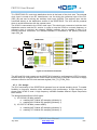
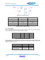
FMC150 User Manual
4.4
r1.
Analog input channels
The AC-coupled input uses wideband RF transformers (TC1-1T). Two transformers are used
to compensate for imbalance and reduce harmonic distortion. A capacitor in front of the
transformer blocks the DC path to ground. This protects the signal source if a DC-coupled
signal with offset is accidentally connected to the FMC150.
The input impedance is matched to 50Ω behind the transformers by terminating each node to
the common mode voltage of the ADC. The R-C-R filter near the input of the A/D converter
can be used to improve performance when lower input bandwidth is required. This filter is
assembled by default.
4.5
Analog output channels
The AC-coupled output uses wideband RF transformers (TC4-1W). An optional reconstruction
filter is available on each DAC output. Refer to Table 2 for the filter characteristics. The filter
can optionally be bypassed on the board by 4DSP. Please contact sales for details on this
option.
Figure 4: Optional DAC reconstruction filter
4.6
External trigger input
The external trigger input is configured as a single-ended input. The allowed input range is
ground and 3.3V. The trigger threshold is set to 1.65V
4.7
Clock tree
4.7.1 External clock input
There is one clock input on the front panel that can serve as a sampling clock input or as a
reference clock input if the internal clock is desired.
Note: When the internal clock is enabled and there is no need for an external reference,
it is highly recommended to disconnect the external clock input to prevent interference
with the internal clock.
4.7.2 Architecture
The clock architecture of the FMC150 card combines flexibility and high performance.
Components have been chosen to minimize jitter and phase noise and reduce degradation of
the data conversion performance. The user may choose to use either an external or internal
sampling clock.
FMC150 User Manual
July 2013
www.4dsp.com
- 11 -