1
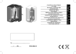
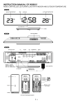
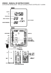
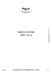
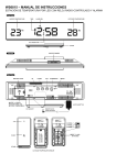
- 20 -
®
CENTRAL HEATING
SOLID FUEL BOILER
KALVIS-5-16(10), 5-20, 5-30
KALVIS-5-16(10)W, 5-20W, 5-30W
USER‘S INSTALLATION
AND OPERATION MANULA
Barcode
LST EN 303-5
ГОСТ 9817-95
ĮST 144948958.13:2004
KALVIS – 5..., KALVIS – 5...W EN
2009.05.18
Notice: Request should be sent by a registered mail to the address specified in this passport, in case of emergency call
specified phone number.
Signature
Name
Surname
Phone number.
My address
If the aforementioned defects are due to wrong installation and operation of the fireplace I shall cover the arrival costs of
your representatives (_______) and the time spent for travel and on site at _____/hour for each representative including the
driver.
1 fig.
1.Ash tray. 2.Cast iron door. 3.Exhaust damper. 4.Servicing
covers. 5.Hot water pipe. 6.Insulating shields. 7.Draught adjuster.
8.Thermomanometer. 9.Draught damper. 10.Ignition damper.
11.Fuel loading door. 12.Refractory bricks. 13.Secondary air pipe.
14.Secondary air damper. 15.Fire grate. 16.Return water pipe.
17.Drainage pipe. 18.Air supply damper. 19.Servicing door.
20.Electric heating. 21.Exhaust damper’s handle. 22.Ignition
damper’s handle. 23.Removable refractory brick (only for
K-5-16(10) and K-5-16(10)W types). 24.temperature sensor
socket*. 25.Cooling water supply pipe*. 26.Cooling water exit
pipe*.
Letters mark dimensions provided in the basic engineering data table.
* Boiler cooling is only installed in "Kalvis-5-...W" types of boilers.
1.
Central heating solid fuel boiler "Kalvis-5-...", "Kalvis-5-...W" (hereinafter
referred to as the boiler) is used for heating various premises where central
heating system with natural or forced circulation is arranged.
Boiler has a socket for mounting 3x1,5…3x2 kW electric heating devices
(with 2“ thread) with temperature control and emergency thermostats or
without them (devices not included).
Having acquainted with fireplace‘s “Kalvis________” user‘s manual (Products No.________ ) and having installed it as
required I have following claims:
1. Basic engineering data
Guarantee servicing request
possible.
To _________________________________
Get acquainted with this technical certificate before installing the
boiler. It shall help you to mount and operate the boiler as efficiently as
F-02/IN-04
ATTENTION !
I consider it a manufacturing error and I ask you to send your representatives to inspect the fireplace, determine the defects
and remove them.
- 19 -
-2-
-3-
- 18 -
Boiler sold
by:
Basic engineering data:
Company
Sales date:
Address
Phone
Boiler type
Nominal output*, kW
Minimum output*, kW
Area heated when the thermal resistance of
the building is 2,5, m2
Fuel used
Boiler
installed by:
In case of a
breakdown
contact
Company
Address
Phone
Foreman
(name, last name, signature)
Company
Address
Phone
Manufacturer
UAB “Šiaulių tauro kalvis”
Pramonės 15,
LT-78137 Šiauliai, Lithuania
Phone: (+370 41) 540556
E-mail: [email protected]
Wood size L x Ø, iki, cm
Combustion chamber volume, dm3 (l)
Fuel* combustion duration, val.
- at nominal output:
- at minimm output:
Fuel used per heating season, m³
Efficiency at nominal output not less than, %
Boiler grade according to EN 303-5
Water volume in the boiler, l
Water pressure in the boiler, not greater than,
MPa (kgf/cm2)
Maximum permitted water temperature in the
boiler, ºC
Minimal return water temperature during
operation, ºC
Ambient temperature, ºC
Temperature adjuster control range, ºC
Parameters for the cooling
pressure, bar
water used to remove
temperat., ºC
excessive heat ***:
Minimum chimney draught, Pa
Exhaust tmeperature*, ºC:
- at nominal output
- at minimum output
Loading hole dimensions, mm
H
Overall dimensions, mm:
B
L
M, G
Connection pipe’s dimensions:
N, mm
D; V1; V2,
Cooling pipe’s dimensions:
G
A
E
Pipe location dimensions, mm:
F
G
Weight (K-5... / K-5...W) not greater than, kg
*
K-5-16 (10)
K-5-16 (10)W
10 **
16
6 **
10,5
60 – 120 **
100 – 200
K-5-20
K-5-20W
20
12,5
K-5-30
K-5-30W
31,5
20
120 – 280
200 – 400
Fire wood, waste wood, saw dust and peat briquettes,
coal
37 x 10
40 x 10
50
80
120
2,8 **
4,8 **
8 – 12 **
2,5
4,0
10 – 16
2,8
4,8
15 – 20
2,8
4,8
20 – 25
74
92
80
3
64
0,15 (1,5)
100
57
3 – 60
65 – 90
≥ 2,0
≤ 15 ***
16 **
18
226 **
165 **
249
180
19
245
178
230 x 2 92
1160
1370
530
530
980
980
G1½-B
Ø158
2009.05.18
242
176
1370
640
1000
G2-B
178 x 178
G ½-B; G ¾-B; G ¾-B
1015
145
140
925
243 / 248
1180
145
145
1115
283 / 288
18-20 % moist content birch wood.
Firing boiler with wood that has more than 30moist content is not recommended%.
** With refractory brick (p.23, 1 fig.) in combustion chamber.
*** For the boilers with installed emergency cooling.
KALVIS – 5..., KALVIS – 5...W EN
21
1190
195
145
1115
400 / 405
- 17 -
-4-
2. Design description
Due to constant development of design, minor inconsistencies with the manual are
possible.
Boiler frame is welded from special sheet steel has water cavities, where water is
heated (see 1 fig.). Internal boiler frame is made of 6 mm thick steel, external – 3 mm.
Exterior of the boiler is covered with insulating shoelds. (p.6). On the front side of the
boiler there is a draught adjuster (p.7), that controls the air supply damper (p.18),
thermomanometer (p.8), door (p.19) beyond which there are cast iron doors (p.2) and
an ash tray (p.1). Loading chamber is closed by the door (p.11). Inside the frame there
is an exhaust damper (p.3) and ignition damper (p.10), that open up the flue way
directly into the chimney and that are used when fuel is ignited or adding more fuel
intot he boiler; also there is a fire grate (p.15) and a secondary air pipe (p.13). In the
secondary combustion chamber there are refractory bricks (p.12) that maintaint he
high temperature of combustion. Below the shields (p.6) there is a servicing cover
(p.4) which allows access for cleaning of boiler internal surfaces.
On the side walls of the boier there are secondary air control dampers (p.14).
On the backside of the boiler there is a drainage pipe (p.17), return (p.16) and hot (p.5)
water pipes; smoke outlet with a draught damper (p.9).
On the side wall of K-5...W there are pipes for the emergency cooling. In the hole
(p.24) (G ½-B) a bushing with the temperature sensor is mounted. Water from the
main is connected into pipe (p.25) (pressure 4 ÷ 2 bar.); (p. 26) is for removanl of
heated water.
Electric heating device automatically turns electric heating on, when fuel runs out
and temperature fall to the preset stand-by mode temperature.
In the combustions chambers of boilers K-5-16(10) and K-5-16(10)W there is a
removable refractory brick (p.23). When it is set into the boiler, boiler output may be
decreased from 16 to 10 kW, prolonging the combustion duration
It is prohibited to alter the design of the boiler.
10. Complement.
1. Boiler "Kalvis-5-_________"
2. Poker
3. Grinder
4. Ash scoop
5. Draught adjuster C20/25
6. User’s manual
- 1 unit
- 1 unit
- 1 unit
- 1 unit
- 1 unit
- 1 unit
Electric heating device and temperature valve are not included
11. Guarantee
• Manufacturer guarantees that boiler conforms to conforms to manufacturing
drawings, provisions and regulations of ĮST144948958.13:2004, and LST EN 303-5.
• Manufacturer applies the following guarantee servicing terms from the date of
sales:
- Boiler frame – 24 months.
- Complement – 12 months.
- Consumables (para7) – 6 months.
Manufacturer will repair any malfunctions in the product that appear due to
manufacturers fault.
• Manufacturer will not acknowledge any quality claims for boiler operation and
consequences if the product has been wrongly chosen, mounted, installed or serviced.
I am acquainted with rules of installation and servicing and guarantee policy:
Purchaser:
(name, last name, signature)
3. Transportation and storage
Transport boilers only in the vertical position by all types of covered transport.
Transporting by not covered transport is possible only when the weather is dry. Use
additional protection means to protect boilers against fall downing and scratching.
Striking, turning over or throwing boilers during loading, unloading or transportation
time is strictly prohibited.
The boilers are to be stored in the dry rooms, where is no vapour of chemicaly
active materials.
4. Boiler installation
Boiler has to be installed in the premises that meet, RSN-159-95 and
RPST-01-97 requirements.
It is recommended to have mounted a smoke collecting cobver above boiler. Boiler
should be mounted vertically, or with forward inclination, which would not exceed 1
degree.
When boileri s installed outside of Lithuania it is necessary to meet the national
requirements for installation of such equipment.
KALVIS – 5..., KALVIS – 5...W EN
2009.05.18
-5-
- 16 -
Use only boiler manufacturer’s consumables and spare parts.
8. Fuel types and properties
Combustion heat of absolutely dry wood does not depend on the wood type and
equals 4510 kcal/kg. So in order to compare different kinds of wood we need to
assume their relative weight. 1m3 weighs:
- oak wood
- 500 kg;
- birch wood
- 450 kg;
- fir wood
- 330 kg;
- asp wood
- 330 kg.
The higher wood humidity is, the smaller calorific value. Decrease in calorific
value of humid wood in comparison to 20% humidity wood:
- 30 % humidity
- 10 ÷ 15 %;
- 50 % humidity
- 35 ÷ 40 %.
Fresh cut tree has about 35 ÷ 60 % maist content. Wood cut in the beginning of
winter or hard wood has the least amount of moist.
Peat and wood calorific value is similar.
1 kg of coal gives 2 ÷ 3 times more heat than 1 kg of wood.
Combustion of 1 kg of wood requires 4 ÷ 5 m3 of air, coal – around 10 m3.
The more ash is left – the worse fuel is.
Energy radiation from combustion of 1 dm3 of wood of 20 % humidity:
Wood type
Oak, maple
Ash
Birch
Alder
Pine
Asp
Polar
Fir
Kcal
2520
2460
2270
1900
1850
1810
1680
1610
Kwh
2,93
2,86
2,64
2,21
2,15
2,10
1,95
1,87
Comparison to oak %
100 %
98 %
90 %
75 %
73 %
72 %
67 %
64 %
Average coal caloric value 6500 kcal/kg (7,56 kWh/kg).
9. Certificate of acceptance.
Central heating solid fuel boiler "Kalvis-5-________" factory Nr._____________
conforms to manufacturing drawings, provisions and regulations of
ĮST144948958.13:2004, and LST EN 303-5 and is suitable for comissioning.
Boiler tested at 0,4 MPa pressure.
Hydraulic pressure test date
_____________________
Date of manufacturing ___________________________
Quality assurance manager
___________________________
2 fig.
Recommended distance from the non flammable partitions
4.1. Fire precautions:
* Boiler should be placed on the incombustible material;
* If boiler is connected to the chimney by metal pipes, pipes should be not thinner
than 1,5mm and they have to be covered by thermal insulation
Attention !
When chimney’s draught is too great and sawdust is used for fuel sparks may fly
out through the chimney.
It is prohibited to use sawdust for fuel, if the distance between chimney and
flammable roof or other flammable structures is less than 20 m!
4.2. Requirements for chimney
Chimney design and boiler connections into it are shown on the fig 2 and 3.
• Chimney draught is not less than specified in main technical data table;
• Chimney
hole‘s
cross
section
should
be
not
less
than
120x270 mm;
• Boiler needs a separate hole for the chimney connection. No other connections
through that hole are allowed.
• If chimney is connected with additional elbow, it‘s cross section has to be not less
than that of the boiler smoke pipe, and bending radii not less than 100mm;
• Pipe from the smoke pipe to chimney may not be longer than 1,5 m and lean
upwards toward chimney;
KALVIS – 5..., KALVIS – 5...W EN
2009.05.18
- 15 -
-6Malfunction
Boiler overheats
Reason
Too intensive combustion.
Power outage (for systems
with forced circulation).
Power outage
Boiler does not reach Bad, humid fuel.
Poor draught.
nominal output
Bad fuel.
Return watrer temperature
Boiler “tears”
is too low (>57°C !).
Poor draught.
Boiler overheats.
Protection valve
Overpressure in the
malfunctions.
boiler
Expansion tank
malfunctions.
Removal
Close air supply dampers, monitor boiler
temperature.
When temperature falls return to the regular
firing.
Call the electrician.
During winter when the power is out for a
prolonged period of time when there is a risk
of system freezing down, drain the system.
Use dry fuel, open up ignition damper.
Check chimney draught.
Use dry fuel.
Adjust the mixing valve.
Close air supply dampers, monitor boiler
temperature.
Check and replace in case of necessity
protection valve and an expansion tank.
6. Safety precautions
It is prohibited to:
3a fig.
Boiler to chimney connection.
* not less than 60° A - incorrect B – correct
3b fig.
Chimney insert installation
3c fig.
• Joints have to be well sealed;
• Chimney hole has to be cleaned periodically.
It is necessary to know that:
• Smoke continues to cool in the chimney, vapor condenses on the chimney walls,
especially in the unheated loft and on the outside of the building;
• Condensate acids and erosion may destroy the chimney in few years;
• Not cleaned soot in the chimney may self-combust and become the cause of fire.
• Disassemble boiler or electric installation;
• Connect boiler to the system without protection valve, that keeps pressure in the
system below 0,15MPa (1,5 kgf/cm2);
• Close hot or return water valves when boiler is operated;
• Store dry fuels or other combustible materials close to or on top of the boiler;
• Store fuel closer than 500 mm to boiler;
• Ignition fuel with combustible liquids (petroleum, kerosene etc.);
• Operate boiler with doors and covers open;
• Allow children into the boiler room without adult supervision;
• Operate boiler with electric heating devices without having it grounded;
• Rapidly open loading doors during combustion (open a little, wait, then slowly
open wide);
Necessary to:
• Monitor grounding efficiency.
7. Consumables
Glazing gaskets, secondary air pipe, fire grate and cast iron doors, refractory bricks
may all fail during operation.
Consumables may be purchase from authorized distributors or the manufacturer of
the boiler.
KALVIS – 5..., KALVIS – 5...W EN
2009.05.18
-7-
- 14 -
Firing the boiler requires a lot of air, so it is important that the sufficient amount is
supplied into the boiler room.
Recommended fuel moisture content is not greater than 15-22 %.
Notice: Upon ignition of fuel, when there is still no sooth on the boiler internal
walls, water condensate forms that gives the impression that the boiler is not water
tight. Water vapour condensate disappears when the temperature in the boiler reaches
70-80°C degrees. It is recommended to keep the water temperature in the boiler as
high as possible. When the return water temperature is lower than 57°C, water
vapours condense on the internal boiler walls and condensate together with products
of combustion forms aggressive acids that may significantly decrease the lifespan of
the boiler.
To make sure that the boiler is water tight it has to be fired intensively for several
hours. The firing has to be stopped and the amount of condensate forming has to be
monitored. If the amount of condensate does not increase – boiler is water tight.
It is recommended:
•
Install a stainless steeel insert in the chimney. Well installed insert protects chimney
from the effects of condensate and moisture;
• Insert should not significantly decrease chimney hole’s cross section;
• Connected parts of the insert should be well sealed (not by soldering);
• Condensate collector should be mounted in the bottom;
• The gap between the chimney and an insert should be filled with non flammable
material at least at the top of the chimney. The gap on top should be sealed and covered
with steel sheet with a lean towards the edge of the chimney;
• Chimney in the cold loft should be insulated by a non flammable insulation;
• If residue in the chimney catches fire close the air supply into the boiler and call the
firefighters.;
• Arrange holes in the chimney connection for periodic sooth cleaning (once in a
month);
• It is recommended that chimney is inspected at least once a year by a qualified
chimney supervisor.
5.3. Installing and adjusting the draught adjuster
Draught adjusters manufactured by Swedish ESBE C20/25 with protection from
boiler overheating or without it are used. Adjuster is turned into a socket, scotch tape
is used for sealing, Attach chain to air supply damper.
When boiler heats up to 70°C, adjust adjusters handle to position "4" and shorten
the chain so that, air supply damper is closed. Turning adjuster to the correspondent
position sets desired temperature. Position "6" corresponds to 90°C. Temperature
increment between positions is 10°C.
5.4. Katilo valymas.
Ash that settles down beneath the fire grate may restrict air acces to the
combustion chamber. Ash tray and ash pit has to be emptied once every 2 days.
In order to ensure efficient boiler operation sooth from the internal boiler frame
walls has to be periodically. Cleaning intervals depend on fuel quality (especially
moisture content) and chimney draught. Cleaning should be performed when the layer
of sooth reaches 3mm, but not less frequently than 2-3 times per month. Remove
covers p4 and dampers 3; 10 before cleaning the internal boiler surfaces.
Hard solids may be removed by chemical cleaners. Swedish „Fauch 300“ cleaner
or cleaners used for fireplaces glass may be used.
Chimney should be cleaned at least once a year before the heating season.
Notice: During the first ignition (or after not having fired the boiler for a long
time) smoke may be blocked in the chimney. In such an event, during ignition, open
up the chimney connection or cleaning hole and stick a burning piece of paper through
it. Close the door when it burns down. Draught should improve.
5.5. Possible dangers and means of their removal
Boiler is protected against the overpressure by the protection valve and the
expansion tank.
4.3. Requirements for the connection to the heating system:
• Boiler may be connected to the heating system according to the project prepared
by heating equipment specialists or works may be performed by a well qualified
plumbing welder who is well acquainted with this manual and boiler design.
• Boiler should be connected by hot and return water pipes not smaller than 1.5’’ in
diameter
• Boiler may be connected to the heating system with the expansion tank, where
operating pressure does not exceed 0,15 MPa (1,5 kgf/cm2);
• If system pipes have valves, that disconnect boiler from the system, mounted, they
have to be fully opened. To avoid break down due to inadvertence, valve handles
should be removed.
• It is necessary to mount the protection valve that keeps the operating pressure in
the system not greater than 0,15 MPa (1,5 kgf/cm2). Valve‘s operation should be
checked upon ignition by turning it‘s handle.
•
In order to avoid forming of the condensate, which may significantly reduce the
lifespan of the boiler it is necessary to install the four way mixing or thermostatic valves
intot he system (see recommended connection schemas). These valves allow to maintain
the return water temperature not lower than 57°C;
• it is recommended that boiler is inspected at least once a year by a qualified boiler
supervisor;
• Drainage pipe is used to remove water from the boiler and the system when there is a
risk that the system will freeze..
•
Recommended boiler connection schemans are shown in fugures 4a – 4d.
When boiler is operated at lower than nominal output efficiency drops,
environmental indicators are getting worse as well. In case of an emergency (when
the circulation pump is not working) boiler may overheat. That is why it is
recommended to use boiler connection schemas with accumulation tanks (fig. 4c,
4d). Minimum volume of the accumulation tank has to be calculated according to
the formula given by the fig. 4d.
KALVIS – 5..., KALVIS – 5...W EN
2009.05.18
- 13 -
-8-
5. Servicing of the boiler
Only adults that are well acquainted with the design and users manual may service
the boiler.
Attention! When firing the boiler with humid fuel or sawdust condensate and
combustible gases form acids that significantly decrease the lifespan of the boiler.
Firing boiler with fine fuels is prohibited due to a danger of explosion and
draughting out of the burning particles through the chimney.
5.1. System preparation for heating
Fill system with water and let the air out. Check if valves disconnecting boiler
from the heating system are fully opened and remove their handles.
5.2. Firing the boiler (fig. 1)
Open exhaust damper (p.9) and ignition damper (p. 10) before firing the boiler.
Place some chopped wood on the fire grate through the door (p.2)and ignite it.
Secondary air pipe’s (p.13) dampers have to be closed. Dampers (p.14) are adjusted
reguliuojamos, when water temperature in the boiler rises up to 60°C.
When fuel is well ignited, combustion chamber may be loaded with fire wood or
coal. Ignition damper (p.10) is closed. Finer wood increases boiler output. Chimney
draught is adjusted by damper (p.9).
Wood should be loaded freely, so that it is able to fall down during combustion.
Coal is addwed in layers, depending on quality and required heat amount. 10cm
thick layer of coal should be added for about 5-10kg of fire wood.
When adding more fuel:
- Open exhaust damper (p.3);
- Open ignition damper (p.10);
- Open door (p.19) and check if the ash does not block the air passages in the fire
grate. Stir the bottom layer of fuel if necessary;
- Remove the chain of the draught adjuster (p.7) from the damper (p.18), so that
the damper is tightly closed;
- Open up the loading door (p.11) slightly, in 5...10 seconds open it fully and add
more fuel;
- Close loading door and dampers tightly;
- Attach the draught adjuster’s chain to the damper.
Check the smoke color flowing out of chimney. Smoke should be thin of a light
grey color. If smoke is thick and black it means incomplete combustion, not enough
secondary air. Open secondary air supply dampers.
As a part of combustion process ash is formed, it blocks the openings in fire grate,
boiler output and combuistion intensity drops. Stir the fuel and ash. Excessive ash in
an ash tray blocks primary air supply, that is why ash needs removal.
Keep the loading doors (p.11) shut when firing the boiler.
KALVIS – 5..., KALVIS – 5...W EN
2009.05.18
-9-
- 12 -
4.4. Boiler cooling system connection
A cooling loop is installed into the boiler Kalvis-5-...W which serves as a
protection against overheating.. When water in the boiler heats up to 95°C valve is
opened and cold water from the main flowing through the cooling loop cools the water
in the boiler. Water after the boiler is directed into the sewer via pipes that are not
smaller than pipes shown in 1 fig., p. 26. (water has to flow freely into the sewer).
Honeywell TS 130 tmeperature valve is included.
In case of a power failure in the house where the water supply is local (water is
supplied by a pump) boiler may overheat (water circulation pumps stopped). It is
necessary to have an additional water supply into the cooling system f. e. an extra
tank.
Recommended cooling schemas are shown in 4a – 4d figures.
Cooling loop may also be used for preparation of a small quanity of hot sanitary
water. Tests show that when the water temperature in the boiler is 75ºC, and the
temperature of the water supplied into the cooling loop at 2.2l/min is 15ºC, water in
the cooling loop upon exit warms up to 42ºC. But when the water flow is increased up
to 5 l/min., temperature upon exit reaches only 32ºC. In order to use the cooling loop
for whot sanitary water preparation it is necessary to know that the temperature upon
exit depends on:
- Boiler water temperature;
- Temperature of water upon entrance into the cooling loop and the amount of hot
water used, i.e. the water flow through the cooling loop.
4.5. Requirements for electric connection
If electric heating devices are installed:
• Electric heating devices may be installed into the boiler when boiler was
connected to the system according to fig. 4a;
• Only a qualified and licenced electrician may install the heating devices;
• Installation works should be performed according to the prepared project
(assuming the total output of the main.).
Recommended electric heating device connection schema is shown on fig. 5.
Pos.
Name
q-ty
F1-F3
Automatic switch
3
E
Heating device
(fixing thread
G2B L=400)
1
16A
3x1,5 kW
3x2 kW
5 fig.
Recommended electric heating device connection schema
KALVIS – 5..., KALVIS – 5...W EN
2009.05.18
- 11 -
- 10 -
KALVIS – 5..., KALVIS – 5...W EN
2009.05.18