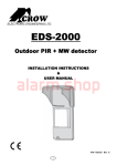
1
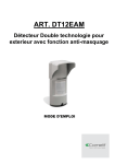
ART. DT12EAM
Dual-Tech Sensor Antimask function
USER MANUAL
Features
Microwave detection based on Doppler concept.
N.O relays switched at the same time.
Installation height is calibration free from 1.8m to 2.4m (5.9 to 7.8 ft)
PIR sensitivity adjustment.
MW intensity selection.
Temperature compensation.
Microcontroller signal processing.
Anti mask mechanism (for PIR lens).
Front and back tamper protection.
Unique waterproof and sealed plastic design.
Detection Range: 12m
Detects human intruders walking or running.
No maintenance required.
High RFI/EMI Immunity.
Protection from: direct sunlight, wind up to 30 m/sec, snow and rain, small animals, removal
of top cover and removal from mounting bracket.
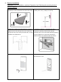
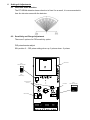
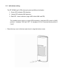
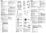
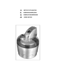
Assembly description
The DT12EAM is a robust yet small detector which includes a large LED indicator that can be
easily observed from long distances to provide indication of intrusion. Using the supplied
mounting bracket, the DT12EAM can be easily mounted to walls using the provided mounting
screws. For installations requiring the detection beam to be adjusted horizontally or vertically to
obtain the desired field of protection use the Outdoor Mounting Bracket pictured below. (not
included)
DT12EAM Outdoor Motion Detector
Outdoor Mounting Bracket
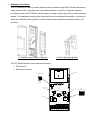
The DT12EAM consists of two detection elements:
NC
MW antenna
SW1
FACTORY SETTING
2
1 2
SW1
MW sensitivity
SW DIP-2
Anti mask module
connector
PIR sensor
PIR
PIR sensitivity
POT
SW DIP-4
1M
NC
1K
845R
HEADER 2X4
HEADER 2X2
SW2
FACTORY SETTING
1 2 3 4
NC
IR-78
2.61K
1K
3.48K
HEADER 2X4
BLOCK 10
2.61K
365R
Microwave element
845R
100R
PIR element
365R
DM-03S-1P
1
HEADER 2X4
3.48K
2
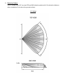
Detection Pattern
The DT12EAM has a 90° top view PIR and MW detection pattern with 12m detection distance
(when installed at 2.4m above the ground surface).
DT12EAM
3
Selecting mounting location
The installation of the DT12EAM requires straight and solid base for the detector and setting
of front panel against the center of protected area.
The protected area must be free from obstacles like walls, fences, trees, ditches and
other microwave detectors, as well as systems of anti-intrusion
surveillance.
The bracket provides DT12EAM installation on a wall. The wall
should be leveled.
Choose a location most likely to intercept an intruder according
to detection pattern on page 5.
Avoid the following Installation Locations:
Facing direct sunlight.
Facing areas subject to rapid temperature changes.
Mounted at more than 10º from the vertical or horizontal plane.
Facing metal doors.
Near direct sources of heat or airflow.
Clear all physical obstacles from the detection area
(e.g. plants, laundry, etc.)
Clear all light reflecting surfaces from the detection area,
including puddles or other standing water.
Avoid installation on the following types of ground:
Thick vegetation, Grass (un-mown), Water, Sand and Metal.
NOTES:
Recommended installation height is 2.1m (6.8 ft).
The PIR sensor detects motion crossing the beam; it is less sensitive detecting motion
towards the detector.
The DT12EAM performs best when provided with a constant and stable environment.
In order to ensure suitable operation of the DT12EAM, the type of ground should be one of
the following: Asphalt concrete, Cement, Soil, Clay, Gravel or Grass (mown).
4
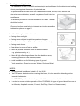
Detector Installation
Important! Prior to installation, read both “Operation” and “Selecting the mounting location”
sections carefully.
1. Install the detector in such manner that the intruder is
2. The detector is to be installed at height of 1.8 to 2.4
most likely to cross the detection area from side to side.
meters (5.9 to 7.8 ft) , ideally 2.1m (6.8 ft)
3. Make sure to attach the metal bracket to a leveled
4. Placing the detector on perpendicular wall is
straight and firm wall, leaving 10cm (3.9 inches) from
required for guarding a side window opening.
the top and 10cm (3.9 inches) from both sides, for easy
Alternately the LC-B1-15X Outdoor Mounting bracket
installation and maintenance.
can be installed on the same wall, allowing the
detector beam to be rotated towards the window.
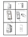
5. Open the detector unwinding the bottom screw.
6. Release the rear metal bracket by unwinding
internal bottom screw.
8. Attach the rear bracket to the wall using mounting
7. Release the detector body from the metal bracket by
screws.
pulling the detector up and out.
9. Insert wires through provided access hole and wiring
10. Attach the sealing sponge pad to the wire opening
channels.
from the rear side after the wires have been
connected and prior to final product affixing to the
mounted bracket.
11. Place the detector on the mounting bracket from top
side down and then lock the screw at the bottom.
12.
5
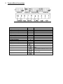
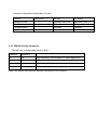
Terminal Block Connections
JUMPER
J5 (EOL TAMPER)
J5 (EOL TAMPER)
J5 (EOL TAMPER)
J5 (EOL TAMPER)
J7 (ALARM)
J7 (ALARM)
J7 (ALARM)
J7 (ALARM)
J6 (AM/TROUBLE)
J6 (AM/TROUBLE)
J6 (AM/TROUBLE)
J6 (AM/TROUBLE)
J8 (2/4)
POSIZIONE
1
2
3
4
1
2
3
4
1
2
3
4
VALORE RESISTENZA
1,8 k
DIDN’T USE
DIDN’T USE
DIDN’T USE
1,8 k
3,3 k
DIDN’T USE
DIDN’T USE
DIDN’T USE
3,3 k
DIDN’T USE
DIDN’T USE
Connessione interna tra FOUT e TIN
J8 (2/4)
Connessione interna tra AOUT e
FIN
J8 (2/4)
Connessione interna tra AOUT e TIN
J8 (2/4)
Connessione interna tra AOUT/FIN
e FOUT/TIN
J8 (2/4)
Non usare
Terminal 1 - Marked “+” (+12V) - Connect to a positive Voltage of 9.6 -16Vdc source
(Usually from the alarm CP)
Terminal 2 - Marked “-” (GND) - Connect to the ground of the CP.
Terminal 3 –Marked "Test" 9.6-16 v on this pin will enter the DT12EAM to walk test mode
even if SW2 position 1 is off
Terminals 4 & 5 - Marked “ALARM” - These are the output relay contacts of the detector.
Connect to a normally closed or normally opened zone in the control unit. When an
intruder is detected, alarm relays (N.C. and N.O.) will switch for 1.8 sec.
Terminal 6&7 - Marked “AM/FAIL" These are the output of the anti mask and Trouble relay
(N.C. and N.O.) Will switch if one from the following scenario happens:
The supply voltage is under 8.5v
Mask detection (will restore if the mask is removed)
PIR or MW self test fail (every 10 hours the detector made self test for PIR and MW
sensors)
Terminal 8 - Marked “TEOL” - End of line – optional terminal for end of line resistors
connections.
Terminals 10 & 9 - Marked “TAMPER” - If a Tamper function is required connect these
terminals to a 24-hour normally closed protective zone in the CP.
If the top cover of the detector is opened or the detector is detached from installation wall,
an immediate alarm signal will be sent to the CP.
Settings & Adjustments
6.1 Detection beam direction
The DT12EAM detection beam direction is fixed. As a result, it is recommended to
face the intrusion area with the detector.
6.2 Sensitivity and Range Adjustment
There are 2 options for PIR sensitivity option:
PIR potentiometer adjust
SW position 3 – PIR pulse setting when up- 2 pulses down -3 pulses
NC
MW antenna
SW1
FACTORY SETTING
2
1 2
SW1
MW sensitivity
SW DIP-2
Anti mask module
connector
PIR sensor
PIR
100R
POT
SW DIP-4
1M
NC
HEADER 2X4
HEADER 2X2
1K
3.48K
HEADER 2X4
BLOCK 10
2.61K
365R
2.61K
845R
1K
845R
365R
PIR sensitivity
SW2
FACTORY SETTING
1 2 3 4
NC
IR-78
DM-03S-1P
6
HEADER 2X4
3.48K
General configuration setting table (for sw2)
Feature
Sw position
On (up)
Off (down)
Indication LEDs
1
Indication LEDs on
Indication LEDs off
Anti Mask
2
ON
Off
PIR pulse count
3
2 pulses
3 pulses
Pet immunity
4
On
Off
8.2.2 MW Sensitivity adjustment
The MW has 4 configurable levels by SW1:
Position 1
Position 2
up*
up*
High sensitivity more suitable for indoor application*
up
down
High sensitivity for outdoor application
down
up
Medium sensitivity for outdoor application
down
down
Low sensitivity for outdoor application
*Note: This setting can affect the detection sensitivity of the infrared
8.3 Indications setting
The DT12EAM has 3 LEDs that each points at different indication:
1. Green LED indicates PIR detection.
2. Yellow LED indicates MW detection.
3. Red LED - alarm indication (logic AND of both MW and PIR)
The installer has an option to control LEDs operation, using the LED control on SW2
position 1, between “ON” and “OFF”. Or by apply 9.6-16v to terminal block position 3
("test")
•
Place the top cover to the base and close it using the bottom screw.
9. Anti mask
The DT12EAM has a sophisticate anti mask module:
This module is assembled on the DT12EAM main board.
To activate the AM please pull up SW2 position 2 .
The DT12EAM has aambient light sensor.
The DT12EAM made self calibration for the anti mask 30 minutes after power up.
Please be verify during installation that the DT12EAM is closed well before 30 minutes
from power up.
If the first power up is under direct sunlight the DT12EAM will made the self calibration 30
minutes after the sun light intensity will decrease
10
Operation
Note! Connect the DT12EAM to a positive Voltage output of 9.6 -16VDC
Use only a listed power limited source.
The detector shall be provided with minimum of 4 hours of standby power from either a
listed compatible control unit or power supply.
The detector is automatically operated once connected to power.
The LEDs start flashing one at a time (side to side) for 30 seconds during the warm-up
period and after that it will turn off.
At this time the detector is ready for operation.
11 Test procedures
Walk Test
Make sure LEDs control is set to “ON”
Allow 30 seconds of warm up time.
Make sure that the protected area is cleared of all people.
Start walking across the detection zone.
Look at the LEDs whenever motion is detected - all LEDs are turned ON.
Allow 5 sec. between each test for the detector to stabilize.
Upon installation, the unit should be thoroughly tested to verify proper operation.
Walk across the entire area where coverage is desired. Should the coverage be incomplete,
readjust sensitivity or relocate the detector.
Once coverage is as desired the LEDs may be disabled.
NOTE: Walk Test procedure should be conducted, at least once a year, to confirm
proper operation and coverage of the detector.
12 Specifications
Detection Method
PIR AND MW
10.525GHz
Microwave Frequency
Power Input
9.6 to 16Vdc
Active: 24mA (±5%)
Current Draw
Standby: 21mA (±5%)
Temp Compensation
Dual slop temperature compensation
Alarm Period
2 sec (±0.5sec)
Form C (NC, NO, Common)
Alarm Outputs
28Vdc 0.1 A with 10 Ohm
Two Switches
Tamper Switch(s)
N.C 28Vdc 0.1 A with 10 Ohm Series protection resistors
Opens when cover is removed from unit’s base
Warm up Period
30sec (± 5sec)
RF Immunity
10 V/m plus 80% AM from 80 MHz to 2GHz
Electrostatic Immunity
6kV contact, 8kV air
Transient Immunity
1kV
Operation Temp
-35ºC ~ +55ºC
Dimensions
160 mm x 70 mm x 45 mm
Weight
210gr.
European directives
RTTE , EMC, Low Voltage, RoHS
USA & Canada
47CFR part 15, subpart C, section 15.245, 47CFR part 15,
subpart B
RSS210, ICES-003
Protection Degree
IEC 60529: IP 64
* Specifications are subject to change without prior notice
.