1
NMEA2000® 16 CHANNEL SWITCH INPUT MODULE
Part Numbers: 4410
USER MANUAL
Revision 1.00
Revision History
Revision
1.0
Description
Original Document
1 Introduction .........................................................2
1.1 Firmware Revision ..............................................2
1.2 Product Features ................................................2
2 Installation ...........................................................3
2.1 Unpacking the box.............................................. 3
2.2 Mounting the unit .............................................. 3
2.3 Connecting the NMEA2000 Cable ......................... 3
2.4 Connecting the Power and Switch Input Cables to
the WAGO socket .....................................................4
2.5 Power and Switch Input Connections .................... 4
3 Configuration.........................................................5
3.1 NMEA Device Instance .........................................5
3.2 NMEA PGNs and Unit Information ..........................5
4 Technical Support .................................................6
5 Warranty ............................................................. 7
1 of 8
1
INTRODUCTION
The Offshore Systems 4410 16 Channel Switch Input Module monitors switch closure devices and
reports their status over the NMEA2000® network.
These devices can include fire/smoke/carbon monoxide detectors, bilge and flood float
detectors, doorway and porthole closure detectors, valve status detectors and many more.
With this module and suitable NMEA2000® displays the status of all these items can be viewed
anywhere on the vessel.
The unit has PLC quality inputs that are manufactured to IEC 61131 and IEC61000 standards so
they are optically isolated and fully protected against ESD, Voltage Surges and Transients to
ensure the most reliable operation at all times.
It is compatible with either 12 or 24 Volt systems and requires NO user setup menus but the
simple setting of two small rotary address switches so multiple Switch Input Modules can exist
on the same network.
The connections to the unit are made via boat builder preferred WAGO Cage Clamp terminal
blocks which allow either solid or multistranded wires from 0.08 to 1.5mm² to be connected
quickly and securely. Each switch input also has a tell tale green LED to indicate when it is
active.
The 4410 can be either panel mounted or din rail mounted using the mounting clips provided.
This unit is designed to operate in a protected marine environment such as an engine room. It is
very important that it is installed and set up correctly according to this manual. Please read and
follow the installation and setup instructions carefully to achieve the best results.
1.1 FIRMWARE REVISION
The information in this manual corresponds to firmware revision 1.00
1.2 PRODUCT FEATURES
The 4410, NMEA2000® 16 Channel Switch Input Module has the following features:
• 16 opto isolated input channels
• PLC quality inputs compatible with standard IEC61131-2 Type 1 and Type 3 Inputs
• Protected against ESD, Voltage Surges and Transients to IEC61000-4-2,4 and 5
• Indicator LEDs for each active input
• Switch settable Device Instance
• Boat Builder Preferred WAGO Cage Clamp Terminals
• Compatible with 12 or 24 Volt Systems
• Panel or DIN rail mounting option
2 of 8
2
INSTALLATION
2.1 UNPACKING THE BOX
You should find the following items in the shipping box:
1 x 4410 16 Channel Switch Input Module
1 x Din Rail mounting Kit with 2 rail mounts and 4 countersunk M3 screws for rails
1 x 4410 User Manual (This document)
2.2 MOUNTING THE UNIT
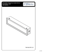
The unit can either be mounted to a flat surface using 4 mounting screws. The unit dimensions
and mounting hole locations are shown on the following drawing.
Or the unit can be Din Rails mounted by attaching the Din Rail mounts to the case using the
supplied M3 CSK screws and then clipping the unit to the Din Rail
2.3 CONNECTING THE NMEA2000 CABLE
The unit is connected to the NMEA2000® network by the 5 way micro C socket on the front.
Carefully attach the network drop cable to this plug and hand tighten until it it is fully seated.
Take care to match the orientation of the pip inside the socket to the recess inside the drop
cable plug. The other end of the drop cable should be connected to a suitable Tee connector on
the NMEA2000 network backbone cable.
3 of 8
2.4 CONNECTING THE SENSOR CABLES TO THE WAGO SOCKET
The cables from the vessels power-source and the switch inputs are connected using the WAGO
Cage Clamp terminal block. The wire should be stripped for 8mm and then the cage clamp
opened with a small screwdriver in the slot above the wire connection. Then simply insert the
wire into it’s connection slot and release the cage clamp by removing the small screw driver.
This will produce a secure gas tight connection on wire sizes from 0.08 – 1.5 mm²
2.5 POWER AND SWITCH INPUT CONNECTIONS
The terminal connections are arranged from left to right as follows:
Terminal 1 + 2
Vessel’s 12 or 24 Volt Power Supply
Terminal 3 - 10
Inputs 0 through 7
Terminal 11 - 18
Inputs 8 through 15
These are all clearly marked marked on the unit case.
Please note the unit HAS to be connected to the vessels DC system using terminals 1 and 2.
These connections are reverse polarity protected and when the connection is correct and
power is applied the green LED by terminals 1 and 2 will illuminate.
The individual inputs are positive active. That is to say the unit recognises a plus 12 or 24 Volt
signal to indicate an active switch input which will illuminate the green LED next to that input.
If you require an input to be negative triggered then you simply need to connect the input
terminal to the ships supply through an 820 Ohm resistor as well as the input wire. Then the
input will be permanently on until the input wire signal is grounded which will turn the input
off.
We have available Part Number 4411 which is our 8 channel Negative Input Adaptor which
provides a group of eight resistors to allow for multiple negative inputs on a 4410 16 Channel
Switch Input Module. If more than 8 negative inputs are required on a 4410 then you will need 2
x 4411.
4 of 8
3
CONFIGURATION
3.1 NMEA DEVICE INSTANCE
Each 4410 NMEA2000® 16 Channel Switch Input Module connected to the NMEA2000® network
needs to have a unique Device Instance Address. The Device Instance of each unit is set by
turning the two small rotary switches with a small screw driver. Valid Device Instances range
from “00” through to “FD”.
3.2 NMEA PGNS AND UNIT INFORMATION
NMEA2000® Parameter Group Numbers (PGNs)
Type
PGN No
PGN Name
Data PGNs
PGN127501
Switch Bank Status Sent on change plus every
2.5 seconds
Protocol
PGN126464
Tx/Rx PGN List
PGN126996
Product Information
PGN059392
ISO Acknowledge
PGN059904
ISO Request
PGN060928
ISO Address Claim
PGN126208
Command/Request Group
Certifications
Parameter
Comment
NMEA2000
Level B
Maritime Nav and RadioComm Equipment
IEC60945
CE and FCC
Electromagnetic Compatibility
Electrical and Mechanical
Parameter
Value
Comment
Operating Voltage
9 to 32 Volts
DC Voltage
Power Consumption
36mA
At 12 Volts
Load Equivalence Number
1
LEN
Reverse Battery Protection
Yes
Indefinately
Load Dump Protection
Yes
SAE J1113
Size
mm
125 x 78 x 38 mm
Weight
gr
180
5 of 8
4
TECHNICAL SUPPORT
If you require technical support for any Offshore Systems products you can reach us using any of
the following ways:
●
●
●
●
●
Tel: +44(0)1425 610022
Fax: +44(0)1425 614794
Email: [email protected]
Web: www.osukl.com
Post: Offshore Systems UK Ltd
Unit 10-11 Milton Business Centre
Wick Drive, New Milton, Hampshire BH25 6RH
Offshore Systems (UK) Ltd
Unit 10 -11 Milton Business Centre, Wick Drive,
New Milton, Hampshire, BH25 6RH, United Kingdom
Tel: +44(0)1425 610022
Email: [email protected]
Fax: +44(0)1425 614794
Web: www.osukl.com
Copyright © 2013 Offshore Systems (UK) Ltd. All rights reserved.Our policy is one of continuous product improvement so product
specifications are subject to change without notice. Offshore Systems products are designed to be accurate and reliable. However,
they should be used only as aids to vessel monitoring, and not as a replacement for traditional navigation and vessel monitoring
techniques. NMEA2000® is a registered trademark of the National Marine Electronics Association.
6 of 8
8
WARRANTY
Offshore Systems warrants this product to be free from defects in materials and workmanship for
one year from the date of original purchase. If within the applicable period any such products shall
be proved to Offshore Systems satisfaction to fail to meet the above limited warranty, such products
shall be repaired or replaced at Offshore Systems option. Purchaser’s exclusive remedy and Offshore
Systems sole obligation hereunder, provided product is returned pursuant to the return requirements
below, shall be limited to the repair or replacement, at Offshore Systems option, of any product
not meeting the above limited warranty and which is returned to Offshore Systems; or if Offshore
Systems is unable to deliver a replacement that is free from defects in materials or workmanship,
Purchaser’s payment for such product will be refunded. Offshore Systems assumes no liability
whatsoever for expenses of removing any defective product or part, or for installing the repaired
product or part or a replacement therefore or for any loss or damage to equipment in connection
with which Offshore Systems products or parts shall be used. The foregoing warranties shall not apply
with respect to products subjected to negligence, misuse, misapplication, accident, damages by
circumstances beyond Offshore Systems control, to improper installation, operation, maintenance, or
storage, or to other than normal use or service.
THE FOREGOING WARRANTIES ARE EXPRESSLY IN LIEU OF AND EXCLUDES ALL OTHER EXPRESS
OR IMPLIED WARRANTIES, INCLUDING BUT NOT LIMITED TO THE IMPLIED WARRANTIES OF
MERCHANTABILITY AND OF FITNESS FOR A PARTICULAR PURPOSE.
Statements made by any person, including representatives of Offshore Systems, which are
inconsistent or in conflict with the terms of this Limited Warranty, shall not be binding upon Offshore
Systems unless reduced to writing and approved by an officer of Offshore Systems.
IN NO CASE WILL OFFSHORE SYSTEMS BE LIABLE FOR INCIDENTAL OR CONSEQUENTIAL DAMAGES,
DAMAGES FOR LOSS OF USE, LOSS OF ANTICIPATED PROFITS OR SAVINGS, OR ANY OTHER LOSS
INCURRED BECAUSE OF INTERRUPTION OF SERVICE. IN NO EVENT SHALL OFFSHORE SYSTEMS
AGGREGATE LIABILITY EXCEED THE PURCHASE PRICE OF THE PRODUCT(S) INVOLVED. OFFSHORE
SYSTEMS SHALL NOT BE SUBJECT TO ANY OTHER OBLIGATIONS OR LIABILITIES, WHETHER ARISING
OUT OF BREACH OF CONTRACT OR WARRANTY, TORT (INCLUDING NEGLIGENCE), OR OTHER THEORIES
OF LAW WITH RESPECT TO PRODUCTS SOLD OR SERVICES RENDERED BY OFFSHORE SYSTEMS, OR ANY
UNDERTAKINGS, ACTS OR OMISSIONS RELATING THERETO.
Offshore Systems does not warrant that the functions contained in any software programs or products
will meet purchaser’s requirements or that the operation of the software programs or products will
be uninterrupted or error free. Purchaser assumes responsibility for the selection of the software
programs or products to achieve the intended results, and for the installation, use and results
obtained from said programs or products. No specifications, samples, descriptions, or illustrations
provided by Offshore Systems to Purchaser, whether directly, in trade literature, brochures or other
documentation shall be construed as warranties of any kind, and any failure to conform to such
specifications, samples, descriptions, or illustrations shall not constitute any breach of Offshore
Systems limited warranty.
WARRANTY RETURN PROCEDUREe
To apply for warranty claims, contact Offshore Systems or one of its dealers to describe the problem
and determine the appropriate course of action. If a return is necessary, place the product in its
original packaging together with proof of purchase and send to an Authorized Offshore Systems
Service Location. You are responsible for all shipping and insurance charges. Offshore Systems will
return the replaced or repaired product with all shipping and handling prepaid except for requests
requiring expedited shipping (i.e. overnight shipments). Failure to follow this warranty return
procedure could result in the product’s warranty becoming null and void.
Offshore Systems reserves the right to modify or replace, at its sole discretion, without prior
notification, the warranty listed above.
7 of 12
8 of 8
9
OFFSHORE SYSTEMS PRODUCT MAP