1
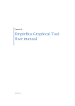
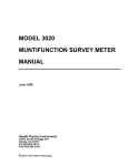
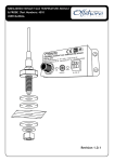
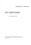
1
USER MANUAL
V1.0.2, Rev A
2
Contenido
PRODUCT OVERVIEW .................................................................................................................... 5
1. INSTALLATION ........................................................................................................................... 6
1.1 Selecting a Mounting Location ............................................................................................ 6
2. MOUNTING THE ALBACOMBI UNIT........................................................................................... 7
2.1 DIN Rail Mounting ............................................................................................................... 7
2.2 Connecting to a NMEA2000 Network ................................................................................. 7
2.2.1 NMEA2000 Networks ................................................................................................... 8
2.2.2 NMEA2000 Minimum Network Requirements ............................................................ 8
3. TACHO INPUT CONNECTIONS ................................................................................................... 9
4. CONFIGURING THE ALBACOMBI DEVICE................................................................................. 10
4.1 General Option .................................................................................................................. 11
4.2 Channel Options ................................................................................................................ 12
4.2.1 RPM Channel .............................................................................................................. 13
4.2.2 PTC1000 Option ......................................................................................................... 15
4.2.3 Volt/Resistive Input .................................................................................................... 17
4.2.4 Shunt Input ................................................................................................................. 19
4.2.5 Voltage Input .............................................................................................................. 20
4.3 Output Option ................................................................................................................... 22
4.4 N2K Option ........................................................................................................................ 23
4.4.1 PGN 127488: Engine Rapide Update .......................................................................... 23
4.4.2 PGN 127489: Engine Parameters Dynamic ................................................................ 24
4.4.3 PGN 127508: Battery Status ....................................................................................... 25
4.4.4 PGN 127505: Fluid Level............................................................................................. 26
4.4.5 PGN 130312: Temperature ........................................................................................ 27
4.4.6 PGN 130314: Pressure ................................................................................................ 29
4.7 Displays Option ................................................................................................................. 30
4.8 FULL-SCREEN OPTION ....................................................................................................... 32
5. HARDWARE TEST AND UPDATE DEVICE OPTIONS .................................................................. 33
SPECIFICATIONS .......................................................................................................................... 35
Company Information
EMMI NETWORK S.L.
CALLE DELS FURS, 50
46701 GANDiA, VALENCIA
SPAIN
[email protected]
www.albacombi.com
No part of this document may be reproduced in any form without the written permission of the
copyright owner.
The contents of this document are subject to revision without notice due to continued progress in
methodology, design and manufacturing. EMMI Network SL shall have no liability for any error or
damage of any kind resulting from the use of this document.
The information provided in this document concerning capacity, suitability and performance shall not be
considered commercially binding.
Please note that all capacity figures and dimensioning methods are based on EMMI Network’s SL own
models of how devices behave in a network. The document is intended to be used by professionally
trained personnel. It is strongly recommended to involve EMMI Network SL in discussions covering the
contents of this document.
Any feedback that may help EMMI Network SL improve the documentation and information methods is
welcome.
Product Disposal
Please dispose of this product in accordance with the WEEE Directive. The product should
be taken to a registered establishment for the disposal of electronic equipment.
5
PRODUCT OVERVIEW
The new AlbaCombi is a second generation device, built following our successful Alba line of converters, that
translate analogue signals from all over the boat to an NMEA2000 bus.
The unit has been designed to connect in parallel to an existing gauge, so existing instruments can still be used.
The AlbaCombi can be used to get engine data, tank levels, alarm status, generic pressure and temperature
indications from any 4-20mA sensor. You get twelve 0V to 32V inputs that can be used for anything from
reading voltages of batteries to interfacing with any analogue gauges. Six channels can be configured to
measure resistance from any industry standard engine sensor. Also there are two RPM inputs, one PTC
temperature input, one shunt and two relay outputs.
All twelve resistance and voltage channels have comprehensive calibration that allow you to create an 8 point
calibration table or select a predefined industry standard calibration table for most common sensors and
gauges.
The AlbaCombi has an Ethernet port that will allow web based calibration. Just connect your laptop to the
AlbaCombi via Ethernet and you will get to the calibration and testing page . No calibration tools or special
interfaces are required. This device is future proof and can be upgraded in the field via its ethernet port.
See the configuration instructions to find which senders and PGNs are supported. The instructions can be
found on the website at www.albacombi.com.
1. Select mounting location:
Ensure the AlbaCombi can be
mounted in a suitable
location
between
the
NMEA2000 bus and the
senders or gauges.
2. Connect the AlbaCombi to
the NMEA2000 network
3. Connect the Gauge inputs
4. Connect the Power to the
AlbaCombi
5. Configure the AlbaCombi
1. INSTALLATION
1.1 Selecting a Mounting Location
The following figure shows an example installation. This gives an idea of the connections that need to be made
to install the AlbaCombi. All these connections need to be considered before selecting an installation location.
Resistive
Mode
RPM
(-)
(+)
12Vdc
2. MOUNTING THE ALBACOMBI UNIT
2.1 DIN Rail Mounting
Requirements:
A top hat rail, type EN 50 022 or a G section rail, type EN 50 035.
Mounting using a different rail type or an alternative mounting kit may breach the terms and conditions of
the guarantee.
2.2 Connecting to a NMEA2000 Network
2.2.1 NMEA2000 Networks
NMEA2000 devices will only communicate with each other when connected to a powered and correctly
terminated NMEA2000 network.
All networks need to be powered and terminated correctly to allow data to be transmitted reliably on the
network. T-Pieces are needed to connect each device to the network. Additional cable lengths can be used
between any of the connectors to extend the length of the network. Ensure the NMEA2000 rules for cable
length are adhered to.
Cable Type
Per drop cable
Sum of all drop cables
Micro Backbone (terminator to terminator)
Mini Backbone (terminator to terminator)
Max Length
6m
72 m
100 m
200 m
2.2.2 NMEA2000 Minimum Network Requirements
All NMEA2000 networks require a 12 V DC supply.
In addition, a correctly functioning network will require the following components :
•
•
•
•
1 x Power-T
2 x Terminating Resistors
2 x T-Pieces (one per connected device)
1 x NMEA2000 compatible display
All the required network parts can be supplied by Emmi Network S.L
3. TACHO INPUT CONNECTIONS
Ignition Coil
Connect the negative of the ignition coil to the positive RPM input of the AlbaCombi.
Connect GND to input GND of the AlbaCombi
Alternator
Connect the ‘w’ connection of the alternator to the
positive input of the AlbaCombi (input (input 5 or
AlbaCombi RPM
6).
Connect GND input of the alternator to the input 4
Hall Effect and Electronic Pulse Senders
Connect the signal line of the sender to the positive input on the AlbaCombi
Connect GND to GND input of the AlbaCombi
4. CONFIGURING THE ALBACOMBI DEVICE
Make all connections. See the pin out of your device:
Configure your AlbaCombi: Connect your laptop to Ethernet port.
Open the browser navigator, preferred Chrome and go to the following address: http://192.168.0.50/
The first windows that you will see are the “FullView” page:
The gauges that you will see are an example
4.1 General Option
In this option you can change the Ethernet configuration from the AlbaCombi, enable/disable the DHCP server
and configure the IP address.
The default configuration is DHCP server disabled and IP address 192.168.0.50.
The default NMEA address is 9.
Note that if you connect two or more AlbaCombi, you must change the NMEA address, for example: you
have two AlbaCombi connected on your NMEA network. One will have the NMEA Address 9 and other will be
configured with NMEA Address 10.
If you make any change, press “Save” button and then press “Reset”
4.2 Channel Options
In order to configure each connected input, please select the channel, as shown on the following screen. Once
selected please configure it.
4.2.1 RPM Channel
You must configure all fields:
Name: the name of the channel.
Signal from: In case of RPM signal, the signal is sent by one engine.
Physic Variable: In case of RPM, the only option is “Rotation Rate”.
Units: RPM
Limits high and Low: these limits will be used to set an alarm.
Filter Level: Please indicate if the level measurement has been made with low, medium or high level.
Sensor Type: you count with some predefined sensors. You can choose a sensor type and make some
changes.
If you press on “Measure”, the current value of the input will be shown.
You can click on RAW and see the current value or you can write the theoretical value of the sensor output
which corresponds to the measurement.
The “Calibrated” button is used to test if your calibration table is correct. Note that you must click on “Save”
before doing the test.
Example: If you have saved the following calibration table:
Measured
(pulse per cycle)
RPM
0 0
600 6000
We assume that the sensor manufacturer indicates these values, therefore 3000 rpm we should have a
measure of 300 pulses per cycle. You can accelerate to see that you have 300 cycles per second (by
pressing on Raw until that value appears), then press “Calibrated” and see the value, if it is about 3000
rpm, the calibration table is correct.
Press “SAVE” when all changes have been made.
4.2.2 PTC1000 Option
Signal from: you can select if the sensor measures the temperature from the engine, battery or it’s a
general temperature. It is important to select the correct sensor because otherwise when configuring
the corresponding PGN you won’t have the choice to select this parameter, for instance, if you choose
Engine, the value will be sent to the NMEA network though the PGN127488 and PGN127489.
Physic Variable: In this case, the PTC sensor only works with temperature parameters.
Units: Select between ºC or K.
Limits high and low: these limits will be used to set an alarm.
Filter Level: Please indicate if the level measurement has been made with low, medium or high level.
Sensor Type: you have some predefined sensors. You can choose a sensor type and make some
changes on calibration table.
If you press on “Measured” you will see the current value:
You can click on RAW and see the current value or you can write the theoretical value of the sensor output
corresponding to the measurement.
The “Calibrated” button is used to test if your calibration table is correct. Note that you must click on “Save”
before make the test.
Example: You has saved the following calibration table:
MEASURED
(Ohms)
VALUE
(Tª) (ºC)
10 15
100 50
180 95
temp;
180; 95
temp
temp;
100; 50
temp; 10;
15
We assume that the sensor manufacturer indicates these values. In this way to 70 ºC we must have a
measure of 140 Ohms. You switch on the engine that you have 140 Ohms (you pressing on Measured until
that value), then press “Calibrated” and see the value, if it is about 70ºC, the calibration table is correct.
Note that X-axis values (MEASURE) must increase, from smallest to largest value
4.2.3 Volt/Resistive Input
You have six inputs like this. In the Channel screen you will see if the input has been configured on voltage o
resistive mode
Signal from: You can select the parameter that the input will measure; engine, battery, general fluid,
general temperature, general pressure, switch bank or general fluid.
Signal from
Engine
Battery
General Fluid
General Temperature
General Pressure
Switch Bank
Physic Variable
Rotation Rate
Pressure
Engine Tilt
Temperature
Voltage
Fluid flow
Temperature
Voltage
Current
General fluid
General temperature
General Pressure
Binary
Limits high and low: these limits will be used to set an alarm.
Filter Level: please indicate if the level measurement has been made with low, medium or high level.
Sensor Type: You have some predefined sensors. You can choose a sensor type and make some
changes.
Supply Correction (only on voltage input, not available on resistance mode):
You can activate the supply correction using a voltage input (Correction Channel)
4.2.4 Shunt Input
The shunt is a sensor that measures the load or unload current in a battery, and it must have the right
dimensions to stand the maximum current it it supposed to measure.
Signal from: This parameter can only be obtained from the battery, therefore, will be the only option
in the drop-down.
Physic Variable: the only option is current.
Units: mA or A
Limits high and low: these limits will be used to set an alarm.
Filter Level: Indicate if the measures filter has been made with a low, medium or high level.
Sensor Type: You have some predefined sensors. You can choose a sensor type and make some
changes.
If you press on “Measured” you will see the current value:
You can click on “Measured” and see the current value or you can write the
theoretical value of the sensor output corresponding to the measurement.
The “Calibrated” button is used to test if your calibration table is correct. Note
that you must click on “Save” before makingthe test.
4.2.5 Voltage Input
Signal from: You can select the parameter that the input will measure: engine, battery, general fluid,
general temperature, general pressure, switch bank or general fluid.
Signal from
Engine
Battery
General Fluid
General Temperature
General Pressure
Physic Variable
Rotation Rate
Pressure
Engine Tilt
Temperature
Voltage
Fluid flow
Temperature
Voltage
Current
General fluid
General temperature
General Pressure
Limits high and low: these limits will be used to set an alarm.
Filter Level: please indicate if the level measurement has been made with low, medium or high level.
Sensor Type: You have some predefined sensors. You can choose a sensor type and make some
changes.
Supply Correction:
You can activate the supply correction using a voltage input (Correction Channel)
4.3 Output Option
You have 2 relay outputs. If you wish to configure alarms:
Name: please write down the alarm’s name
Output Type: you have 3 options:
o Manual: You can switch on/off the relay
o NMEA2000: allows to act on a device connected to the NMEA network when the alarm is
activated
o Alarm: the alarm up and down values are only to be configured on screen.
Limits high/low: these limits have already been configured in the “Channel Option”.
Activation Rule: You can choose the condition for which the alarm is activated.
4.4 N2K Option
In this section you must configure the PGN to send through the NMEA network.
4.4.1 PGN 127488: Engine Rapide Update
Engine
Speed (RPM)
Boost Pressure
7FFFFF
RPM
Instance: The instance indicates the engine (port, starboard, forward, etc..)
Engine Speed: if you have a RPM input, please select it.
Engine Boost: if you have configured a pressure input from engine, please select it.
Tilt/trim: same as before.
Active PGN: If you select this option, the AlbaCombi will send this information through N2K network
and the information will be shown on your multifunction display on board.
4.4.2 PGN 127489: Engine Parameters Dynamic
Engine
Oil Pressure
Oil Temperature
Engine Temperature
Alternator Voltage
Coolant Temperature
The following PGNs which are mentioned in the standard NMEA will be displayed:
Instance: The instance indicates the engine values (port, starboard, forward, etc..)
Oil Pressure: if you have configured a pressure input from engine, please select it.
Engine Temperature: If you have configured a temperature sensor from engine, please select it.
Proceed in the same way with the rest of parameters.
Active PGN: If you select this option, the AlbaCombi will send this information through N2K network
and it will be shown on a muntifunction display on board.
4.4.3 PGN 127508: Battery Status
Battery Instance
Voltage
Current
Temperature
FF
Instance: this is a very important field. If you have two or more batteries on your vessel, each battery
bank should be configured with a different distance.
Range 0 to 250 for valid position fixes.
Voltage: Select the input where you have connected the battery voltage on your AlbaCombi.
Current: Select your shunt input channel.
Temperature: Select the temperature input from battery bank.
Note, enable the “Active PGN” if you wish to display the parameters in your on board NMEA N2K multifunction
display.
4.4.4 PGN 127505: Fluid Level
Fluid Instance
Fluid Type
Fluid Level
Tank Capacity
Reserved FF
Instance: this is a very important field when you have two or more level sensors on your vessel, each
sensor should be configured with a different instance.
Capacity: (cubic meters) You must define the capacity of your tank.
Type: You can select the type as NMEA standard ndicates (Fuel , fresh water, waste water, live well,
oil and black levels).
Level: Select the correct input.
Note, enable the “Active PGN” if you wish to display the parameters in your on board NMEA N2K multifunction
display.
4.4.5 PGN 130312: Temperature
SID
Instance nº
Temperature Source
Actual Temperature
(ºK)
Temperature Set
Reserved FF
Instance: this is a very important field if you have two or more temperature sensors on your vessel,
each sensor must configure with different instances.
Source: You can select the source type as NMEA standard indicates:
Actual Value: Select the correct input.
4.4.6 PGN 130314: Pressure
SID
Instance nº
Pressure Source
Pressure (Pa)
Reserved FF
Instance: this is a very important field if you have two or more pressure sensors on your vessel, each
sensor must configure with different instances.
Source: You can select the source type as NMEA standard indicates:
Actual Value: Select the correct input.
4.7 Displays Option
In this option you will configure the parameters to monitoring in the FullView Option.
Select the first display to configure it:
Select Measurement: You will choose any input that you had connected to AlbaCombi
Title: Display name, you will see underneath the gauge.
Label: name on the gauge label.
Display Type: when displaying the information you can select between the following forms:
o Gauge:
o
Graph:
o
Display:
Activate Full-View: If you select this option, you will see the parameter in the full screen option from
AlbaCombi.
Alarms zone: It is important to set the alarm values as it will define the scale limits on your display.
Please find hereby examples on how to set these
limits:
MIN
Green Zone
Yellow Zone
Red Zone
0
2500
4500
MAX
2500
4500
7000
Note that the upper limit has to be equal to the
area above.
lower limit of the
In case you wish only two zones, the
follows:
configuration is as
MIN
Green Zone
Yellow Zone
Red Zone
0
4500
4500
MAX
4500
4500
7000
Press “Save” when the you have finished configuring the display.
4.8 FULL-SCREEN OPTION
The default page of AlbaCombi will be displayed as shown below.
All displays that you have configured before will be displayed. This option can work in parallel to a NMEA
display.
You can view this data in NMEA display installed in your boat, and also from any device connected to the same
Ethernet network as the AlbaCombi internet based page.
Press on the padlock icon to block/unlock the screen. In unlock mode you will can move the indicators.
5. HARDWARE TEST AND UPDATE DEVICE OPTIONS
Before making all connections, please follow the next steps:
1. Change the state of the switch on Hardware Test Mode:
Switch 1 on, switch 2 off and then press reset button
ON
1
1. Please access the following URL on your PC: http://192.168.0.50/
2. You will see the “Hardware Test” Option:
2
If you connect the test board, the device will be a hardware test and in your web page you will see the
checkbox marked if the result has been positive.
To update the AlbaCombi device:
1.
2.
3.
3.
Download the last firmware version from: www.albacombi.com and save it on your PC
Enter in Installer Mode on your AlbaCombi device.
Go to: http://192.168.0.50/.
Select the “Firmware Update” option:
4. Select the .xin file saved on step 1.
5. Press “Update”.
SPECIFICATIONS
SPECIFICATIONS IN / OUT
6 x Resistive (0 to 600 Ohm) or
Voltage (0-32V)
6 x Voltage (0-32V)
Analogue Inputs
2 x RPM W signal or magnetic sensor
1 x Precision temperature PTC1000
1 x 100mV current shunt
Analogue input
precision
1% or better
Relay out
2 x Open collector output
Ethernet port (calibration and
monitoring)
Data in/out
RS232 (module programming)
Isolated CAN NMEA2000
NMEA2000 Parameter Group Numbers (PGN’s)
PGN127488
Engine Parameters, Rapid Update
PGN127489
Engine Parameters, Dynamic
PGN127508 Battery Status
Periodic
ELECTRIC SPECIFICATIONS
Tension
9-18V DC from the NMEA2000 bus
Consumption
150mA
Equivalent load
3 LEN as per NMEA2000
PGN127505 Fluid Level
PGN130312 Temperature
PGN130314 Actual Pressure
PGN127501 Binary Switch Bank
Status
PGN127502 Binary Switch Bank
Control
MECHANICAL SPECIFICATIONS
104mm x 86mm x 588mm
Size
(DIN 43880 size 6)
Weight
230g
Mounting
DIN Rail Clip EN 50.022
Top PC/UL 94-V0, Base PPO / UL
Case material
94-V0
ENVIROMENTAL SPECIFICATIONS
Protection Class
IP20
EN60529
Working
-15C to +55ºC
temperature
Storage
-25ºC to +85ºC
temperature
93% HR @ 40ºC
IEC60945Relative humidity
8.3
2-13.2Hz @ ±1mm
Vibration
13.2-100Hz @ 7m/s2 IEC609458.7
4x7 days @ 40ºC, 95%HR after
Corrosion
two hour salt spray IEC60945-8.12
Emission
IEC60945-9
E.M.C.
Immunity
IEC6094510