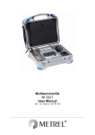
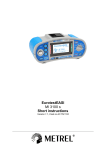
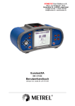
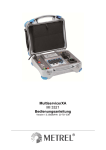
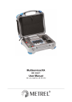
Download MultiservicerXA MI 3321 Short instructions
Transcript
MultiservicerXA MI 3321 Short instructions Version 1.1, Code no. 20 751 520 Distributor: Manufacturer: METREL d.d. Ljubljanska cesta 77 1354 Horjul Slovenia web site: http://www.metrel.si e-mail: [email protected] Mark on your equipment certifies that this equipment meets the requirements of the EU (European Union) concerning safety and electromagnetic compatibility regulations © 2009 METREL The trade names Metrel, Smartec, Eurotest, Autosequence are trademarks registered or pending in Europe and other countries. No part of this publication may be reproduced or utilized in any form or by any means without permission in writing from METREL. 2 MI 3321 MultiservicerXA Safety and operational considerations 1 Safety and operational considerations 1.1 Warnings This document is a supplement to the Instruction manual! Warning on the instrument means »Read the Instruction manual with special care to safety operation«. The symbol requires an action! Read this user manual carefully, otherwise use of the instrument may be dangerous for the operator, for the instrument or for the equipment under test! If the test equipment is used in manner not specified in this user manual the protection provided by the equipment may be impaired! Do not use the instrument and accessories if any damage is noticed! Consider all generally known precautions in order to avoid risk of electric shock while dealing with hazardous voltages! Do not use the instrument in supply systems with voltages higher than 300 V! Use only standard or optional test accessories supplied by your distributor! The protection class of the TP1 test terminal is CAT III / 300V. It means that maximum allowed voltage between test terminals and ground is 300 V! Use only correctly earthed mains outlets to supply the instrument! In case a fuse has blown follow the instructions in this user manual to replace it! It is advisable to not run tested devices with load currents above 13 A for more than 15 minutes. Load currents higher than 13 A can result in high temperatures of On/Off switch and fuse holders! Service intervention or adjustment and calibration procedure is allowed to be carried out only by a competent authorized person! Hazardous voltages exist inside the instrument. Disconnect all test leads, remove the power supply cable and switch off the instrument before removing battery compartment cover. All normal safety precautions have to be taken in order to avoid risk of electric shock when working on electrical installations! Do not touch the test object during the measurement or before it is fully discharged! Risk of electric shock! Automatic discharge of capacitive object will take some time after the finished insulation resistance measurement. Actual voltage is displayed during discharging until it drops below 10 V. In no case the test leads should be disconnected until tested object is completely discharged! 3 MI 3321 MultiservicerXA Safety and operational considerations 1.2 Communication There are following communication interfaces available on the instrument: - PC and external printer, USB or RS 232. - Bar code reader / RFID, RS 232, and - Label printer, special. How to communicate over a PC: Select appropriate communication interface (USB / RS 232) and connect the instrument and PC. Switch on the PC and the instrument. Run the PATLinkPRO program. The PC and the instrument will automatically recognize each other. The instrument is prepared to download data to the PC. Note: USB drivers should be installed on PC before using the USB interface. Refer to USB installation instructions available on installation CD. Communication transfer speed: RS 232....................... 115200 baud USB ........................... 256000 baud Application of bar code reader / RFID: Connect reader to its RS 232 port on the instrument. Select reader option (Bar code / RFID). Read ticker (bar code label, or RFID TAG) on the equipment to be tested. The instrument is prepared to execute autotest related to the tested equipment. Application of label printer: Connect label printer to the instrument. Switch on Label printer. The label printer is prepared for printing. 4 MI 3321 MultiservicerXA Instrument front panel 2 Instrument operators panel Legend: 1 2 3 4 5 6 7 8 9 10 11 12 13 Mains switch with indicator. Two T16 A / 250 V fuses for instrument protection. Mains supply cord. 240 128 dots graphic matrix display with backlight. IEC appliance connector for testing supply cords. Warning! The connector input is for test purpose only; do not connect it to the mains supply! Label printer connector on back side. Test probe (S/C1) connector, used as output for earth bond/ continuity tests and probe input in for class 2 equipment tests (insulation resistance-S, substitute leakage-S and touch leakage currents ). HV test connector output. Warning! A high dangerous voltage of up to 2800 V ac is applied at this output during the measurement! HV_PE test connector return, functional earth of test system. Note: HV source is referenced to earth (PE), this means that there shall be proper prepared set-up for withstanding testing. TP1 test socket for testing line impedance, loop impedance, voltage and residual current devices, discharge time. C2 connector, used as output for continuity tests (in machine, switchboard and All operating modes). LN and PE sockets for testing the insulation resistance and substitute leakage current of fixed installed DUTs. Warning! These sockets are intended only for the connection to deenergized devices. Test socket (230 V). Warning! Dangerous voltage is present on the test socket during the measurement. Maximum 5 MI 3321 MultiservicerXA 14 15 16 17 18 19 20 21 22 23 Instrument front panel output current is 16 A, test only devices with maximum rated supply current not higher than 16 A! Note: For devices incorporating high reactive loading, e.g. motor with rated power >1.5 kW, it is recommended to start measurement first and later to turn on the tested device. Cursor keys and ENTER key. Alpha-numeric keyboard. STOP key. START key. ESCAPE key. Function keys intended for displayed defined options. Current clamp adapter input sockets. Warnings! Do not connect any voltage source on this input. It is intended only for connection of current clamp with current output. Maximum input current is 30 mA! Green socket is connected to the functional earth of the system and is intended for connection with shield of current clamps only. USB connector. PC / printer / A1143 (option) connector. Barcode reader / writer connector. 6 MI 3321 MultiservicerXA Auto sequence 3 Autotest sequences 1 3 4 5 Set function In Main menu select PAT TESTING. Use cursors / to select appropriate autotest type. Use cursors / to select autotest or read label / TAG. 2 Set parameters and limits / .... Select autotest function. EDIT ...... Test function parameters modification menu. / .... Select parameter. / ... Select parameter value. CONFIRM ..... accept new settings. Building autotest procedure In the main menu select proper testing and appropriate auto test. Press the VIEW (F1) key. Repeat until finished: ♦ Select autotest function ( / ). ♦ Press the EDIT (F4) key. ♦ Set mode of the autotest function ( / ). ♦ If enabled until finished: Select parameter ( / ). Select parameter value ( / ). ♦ If modified press the CONFIRM key. Press the key SAVE (F2) if modified existing or the key SAVE AS (F3) if new autotest is prepared. Running auto sequence In the main menu select proper testing and appropriate auto test. Connect the instrument to tested object. Press the START key. Follow the note of current test. ♦ Press HELP for test circuit configuration. ♦ Press SKIP if test shall be omitted. ♦ Press END to finish testing. Press the START key to run the measurement. ♦ Press REPEAT to if necessary to repeat the same test. The sequence will stop when invalid condition of test terminals is detected. It will: ♦ Continue after correct condition is restored. ♦ Skip the target function by pressing the SKIP key or remaining functions and finish the autotest by pressing the ESC key. Results of a finished autotest can be equipped with support data, viewed and stored. View results Displayed results: ..................... Overall PASS result is reported if all performed tests passed. ..................... Overall FAIL result is reported if one or more performed tests failed. 7 MI 3321 MultiservicerXA Measurements 4 Measuring connections 4.1 Inspections 1 2 3 Product groups Autotest: All Single test: Machine, Switchgear Visual inspection procedure Visual verify tested equipment. Mark result of inspection. Store the result (optional). View results 8 MI 3321 MultiservicerXA Measurements 4.2 Resistance of equipotential bonding and to earth connection 1 3 2 Product groups Autotest: All Single test: All Parameters and limits Output .... Test voltage. Limit ........ Maximum resistance to earth connection. Time ......... Test time. Mode ....... Type of measurement. Test circuits for resistance of equipotential bonding and to earth connection PAT 3 Machine and Switchgear View results Mode = Single Mode = Auto Machine and Switchgear PAT Displayed results: - Continuity resistance - 9 Continuity resistances MI 3105 EurotestXA Measurements 4.3 Insulation resistance 1 3 2 Product groups Autotest: All Single test: All Parameters and limits Output .... Test voltage. Limit ........ Minimum insulation resistance. Time ......... Test time. Test circuits for insulation resistance Portable Fixed PAT 3 Machine and Switchgear View results PAT, Machine and Switchgear Displayed result: - Insulation resistance 10 MI 3321 MultiservicerXA Measurements 4.4 Class II Insulation resistance 1 3 Product groups Autotest: PAT Single test: PAT, All tests 2 Parameters and limits Output .... Test voltage. Limit ........ Maximum resistance to earth connection. Time ......... Test time. Test circuits for class II insulation resistance Portable Fixed PAT 3 View results Displayed result: - Insulation resistance 11 MI 3321 MultiservicerXA Measurements 4.5 Substitute leakage current 1 3 Product groups Autotest: PAT Single test: PAT, All tests 2 Parameters and limits Output .... Test voltage. Limit ........ Maximum leakage current. Time ......... Test time. Test circuits for substitute leakage current Portable Fixed PAT 3 View results Displayed result: - Substitute leakage current 12 MI 3321 MultiservicerXA Measurements 4.6 Class II substitute leakage current 1 3 Product groups Autotest: PAT Single test: PAT, All tests 2 Parameters and limits Output .... Test voltage. Limit ........ Maximum substitute leakage current. Time ......... Test time. Test circuits for class II substitute leakage current Portable Fixed PAT 3 View results Displayed result: - Substitute leakage current 13 MI 3321 MultiservicerXA Measurements 4.7 Differential leakage current 1 3 Product groups Autotest: PAT Single test: PAT, All tests 2 Parameters and limits Output .... Test voltage. Limit ........ Maximum differential current. Time ......... Test time. Test circuits for differential current measurement PAT 3 View results Displayed result: - Differential current 14 MI 3321 MultiservicerXA Measurements 4.8 Touch leakage current 1 3 Product groups Autotest: PAT Single test: PAT, All tests 2 Parameters and limits Output .... Test voltage. Limit ........ Maximum touch current. Time ......... Test time. Test circuits for touch leakage measurement PAT 3 View results Displayed result: - Touch current 15 MI 3321 MultiservicerXA Measurements 4.9 Polarity 1 3 Product groups Autotest: PAT Single test: PAT, All tests 2 Parameters and limits Test circuits for polarity test PAT 3 View results 16 MI 3321 MultiservicerXA Measurements 4.10 Clamp current 1 3 Product groups Autotest: PAT Single test: PAT, All tests 2 Parameters and limits Limit ........ Maximum current. Time ......... Test time. Test circuits for clamp current measurement PAT 3 View results Displayed result: - TRMS clamp current 17 MI 3321 MultiservicerXA Measurements 4.11 RCD, PRCD test 1 3 Product groups Autotest: All Single test: PAT, Machine, All tests 2 Parameters and limits MODE ...... RCD Test mode. TEST ........ Type of RCD test. IN............. Rated residual current. Multi ......... Actual test current. Type ......... RCD type. Phase ...... Starting phase of test signal. Test circuits for RCD test PAT 3 Machine View results Uc test Single test Trip-out time 18 MI 3105 EurotestXA Measurements Autotest Trip-out current Autotest PAT Machine Displayed results: - Trip-out time(s) - 19 Contact voltage Trip-out time(s) Trip-out current MI 3321 MultiservicerXA Measurements 4.12 Functional and power test - PAT 1 3 2 Product groups Autotest: PAT Single test: PAT, All tests Parameters and limits Output ..... System voltage. Time ......... Test time. Test circuits for functional, power test PAT 3 View results Displayed result: - apparent power 20 MI 3321 MultiservicerXA Measurements 4.13 Functional test – Machine, Switchgear 1 2 3 Product groups Autotest: Machine, Switchgear Single test: Machine, Switchgear, All tests Scope of the test Visual inspection for proper operation. View results 21 MI 3321 MultiservicerXA Measurements 4.14 High voltage test 1 3 2 Product groups Autotest: All Single test: All Parameters and limits Output .... Test voltage. Limit ........ Maximum insulation leakage current. Time ......... Test time. Test circuits for high voltage test Machine and Switchgear 3 View results Machine Switchgear Displayed results: - HV insulation leakage current - Actual test voltage - Adequacy of insulation 22 MI 3321 MultiservicerXA Measurements 4.15 Line impedance 1 3 Product groups Autotest: Single test: All tests 2 Parameters and limits Test .......... Type of test FUSE type .... Type of fuse. FUSE T ... Fuse rated current. FUSE I ..... Required breaking time Isc_lim .... Minimum short circuit current. Test circuits for line impedance measurement Standard measurement High precision measurement 23 MI 3321 MultiservicerXA 3 Measurements View results Standard impedance High precision Impedance L - N High precision Impedance L - L Displayed results: Standard impedance - Impedance - Prospective short circuit current High precision impedance - Impedance - Resistance - Reactance - Short circuit currents 24 MI 3321 MultiservicerXA Measurements 4.16 Loop impedance 1 3 Product groups Autotest: Machine Single test: Machine, All tests 2 Parameters and limits TEST ........ Type of test. Fuse type .. Type of fuse. FUSE T ... Fuse rated current. FUSE I ..... Required breaking time Isc_lim .... Minimum short circuit current. RCD/Fi .... Rated RCD trip-out current R Lim ....... Maximum loop resistance for selected RCD. Test circuits for fault loop impedance measurement Standard measurement High precision measurement 25 MI 3321 MultiservicerXA 3 Measurements View results Standard impedance High precision impedance Displayed results: Standard impedance - Impedance - Prospective fault current High precision impedance - Impedance - Resistance - Reactance - Short circuit currents - Touch voltage 26 MI 3321 MultiservicerXA Measurements 4.17 Voltage, frequency, rotation field 1 3 2 Product groups Autotest: Machine, Switchgear Single test: Machine, Switchgear, All tests Parameters and limits Test circuits for voltage, frequency and rotation field measurements Machine and Switchgear 3 View results Single-phase Three-phase Displayed results: - Voltage Line – Neutral - Voltage Line – Protective earth - Voltage Neutral – Protective earth - Frequency - 27 Voltage L1 – L2 Voltage L1 – L3 Voltage L2 – L3 Frequency Phase rotation MI 3321 MultiservicerXA Measurements 4.18 Discharge time 1 3 Product groups Autotest: Machine, Switchgear Single test: Machine, Switchgear, All tests 2 Parameters and limits Limit U .... Maximum residual voltage. Limit t...... Maximum discharge time. Test circuits for discharge time measurement Machine and Switchgear 3 View results Displayed results: - discharge time - peak voltage 28 MI 3321 MultiservicerXA Maintenance 5 Maintenance 5.1 Replacing fuses F1,F2 T 16 A / 250 V, 32 x 6,3 mm This fuse protects instrument. Warnings: Switch off the instrument and disconnect all test accessories and mains cord before replacing the fuses or opening the instrument. Disconnect all test leads and the instrument mains cord before removing fuse cover! Replace blown fuse with original type only, otherwise the instrument may be damaged and/or operator's safety impaired! 29


