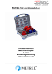
Download Euro Z 290 A adapter A 1143 Instruction manual
Transcript
Euro Z 290 A adapter A 1143 Instruction manual HW 2, Ver.2.2, Code no. 20 751 507 Distributor: Manufacturer: METREL d.d. Ljubljanska cesta 77 SI – 1354 Horjul web site: http://www.metrel.si e-mail: [email protected] Mark on your equipment certifies that this equipment meets the requirements of the EU (European Union) concerning safety and electromagnetic compatibility regulations. Version note User manual versions 2.0 and higher are related to Euro Z 290 A adapter A1143 HW2 (Hardware Version 2). © 2004..2010 METREL The trade names Metrel, Smartec, Eurotest, Autosequence are trademarks registered or pending in Europe and other countries. No part of this publication may be reproduced or utilized in any form or by any means without permission in writing from METREL. 2 A 1143 Euro Z 290 A adapter Table of contents 1 Preface.........................................................................................................................4 2 Safety and operational considerations.....................................................................5 2.1 2.2 2.3 3 Adapter description....................................................................................................7 3.1 3.2 4 Front panel ............................................................................................................7 Instrument set........................................................................................................7 Operation.....................................................................................................................8 4.1 4.2 4.3 5 Warnings ...............................................................................................................5 Battery ...................................................................................................................5 Standards applied..................................................................................................6 Connecting Euro Z 290 A adapter to Eurotest instrument .....................................8 Instrument status (meaning of LEDs) ....................................................................8 Meaning of messages on the Eurotest instrument display ..................................11 Measurements ..........................................................................................................13 5.1 High precision line impedance.............................................................................13 5.1.1 How to perform high precision line impedance measurement .........................13 5.2 High precision fault loop impedance / contact voltage.........................................15 5.2.1 How to perform high precision fault loop impedance measurement.................15 6 Maintenance..............................................................................................................17 6.1 6.2 6.3 7 Periodic calibration ..............................................................................................17 Cleaning ..............................................................................................................17 Service ................................................................................................................17 Technical specifications ..........................................................................................18 7.1 7.2 7.3 7.4 High precision line impedance.............................................................................18 High precision fault loop impedance....................................................................19 Contact voltage....................................................................................................19 General data........................................................................................................19 3 A 1143 Euro Z 290 A adapter Preface 1 Preface Congratulations on your purchase of the Euro Z 290 A from METREL. The electrical installation impedance measuring adapter was designed on basis of rich experience, acquired through many years of dealing with electric installation test equipment. The Euro Z 290 A high current impedance adapter is a professional portable test adapter intended for low impedance measurements in environments up to 310 V CAT IV. It can operate alone or in combination with the METREL instruments. High precision line impedance and high precision fault loop impedance measurements in range from 1 m up to 19.99 are its excellence. Typical applications are impedance measurements in proximity of supply transformers Supported instruments are: - Eurotest 61557 (MI 2086), - EurotestAT (MI 3101), - EurotestXA (MI 3105), and - MultiservicerXA (MI3321). With this, measurement required by standards related to testing electrical installations and connections of electrical equipment (of machines) to electrical installation are covered. The L.C. display offers easy reading of impedance result. The operation of the Impedance adapter A1143 is clear and simple – the operator does not need any special training (except reading this user manual and the user manual of selected master instrument) to operate the adapter. In order for operator to be familiar enough with performing measurements in general and their typical applications it is advisable to read Metrel handbook Guide for testing and verification of low voltage installations. The adapter is equipped with all accessories necessary for comfortable measurements. It is kept in a robust waterproof case together with all accessories. 4 A 1143 Euro Z 290 A adapter Safety and operational considerations 2 Safety and operational considerations 2.1 Warnings and notes In order to reach high level of operator safety while carrying out various measurements using Euro Z 290 A high current impedance adapter, as well as to keep the test equipment undamaged, it is necessary to consider the following general warnings: symbol at the instrument means »Read the Instruction manual with special care«! If the test equipment is used in a manner not specified in this Instruction manual the protection provided by the equipment may be impaired! Read this Instruction manual carefully, otherwise use of the instrument may be dangerous for the operator, for the instrument or for equipment under test! Do not use the adapter and accessories if any damage is noticed! Remove all test leads before opening battery cover. Consider all generally known precautions in order to avoid risk of electric shock while dealing with hazardous voltages! Note that Euro Z 290 A high current impedance adapter is intended for use in environments where dangerous voltages are easy accessible (e.g. switchgears, power stations)! Service intervention or adjustment procedure is allowed to be carried out only by a competent authorized person! Use only standard or optional test accessories supplied by your distributor! Front panel can overheat when performing the rapid sequence of high precision line-to-line impedance measurements. Notes related to measurement functions: Z-LOOP The Z-LOOP impedance function will trip-out the RCD in RCD protected installation that is tested. To prevent the RCD trip-out, make measurements on entry side of RCD or bypass the RCD but only for test purpose. Specified accuracy of tested parameters is valid only if mains voltage is stable during the measurement. Z-LINE Specified accuracy of tested parameters is valid only if mains voltage is stable during the measurement. 2.2 Battery The instrument uses four C size (IEC LR14) alkaline or rechargeable Ni-MH battery cells. Nominal operating time is declared for cells with nominal capacity of 4500 mAh. LED ON indicates battery condition. Blinking LED means weak battery and the instrument prevents any impedance measurement. Weak battery shall be replaced by new or recharged. 5 A 1143 Euro Z 290 A adapter Safety and operational considerations Battery replacement procedure: Disconnect all test leads before opening battery compartment cover, hazardous voltage inside! Turn off the instrument. Unscrew and remove battery cover. Always replace all 4 battery cells. Use always equal type of size C (IEC LR14) battery cells (alkaline or Ni-MH). Insert cells correctly otherwise the adapter will not operate and the battery could be discharged or even damaged. Return battery cover and fix its screws. The instrument is prepared for using. Notes: If the adapter is not to be used for longer time, remove complete battery from the battery compartment. Take into account handling, maintenance and recycling requirements that are defined by related regulations and manufacturers of alkaline or rechargeable batteries! 2.3 Standards applied The Euro Z 290 A high current impedance adapter is manufactured and tested in accordance with the following regulations: Electromagnetic compatibility (EMC) IEC/ EN 61326-1 Electrical equipment for measurement, control and laboratory use EMC requirements - Part 1: General requirements Class A (Hand held equipment used in industrial EM environments) IEC/EN 61326-2-2 Electrical equipment for measurement, control and laboratory use EMC requirements - Part 2-2: Particular requirements - Test configurations, operational conditions and performance criteria for portable test, measuring and monitoring equipment used in lowvoltage distribution systems Safety (LVD) IEC/ EN 61010 - 1 IEC/ EN 61010 - 031 Safety requirements for electrical equipment for measurement, control, and laboratory use – Part 1: General requirements Safety requirements for hand-held probe assemblies for electrical measurement and test Functionality IEC/ EN 61557 Electrical safety in low voltage distribution systems up to 1000 V a.c. and 1500 V d.c. - Equipment for testing, measuring or monitoring of protective measures Part 1 General requirements Part 3 Loop resistance 6 A 1143 Euro Z 290 A adapter Adapter description 3 Adapter description 3.1 Front panel 7 Figure 3.1: Front panel 8 Legend 1...........ON/OFF switch to power on or off the Euro Z 290 A adapter. 2...........Battery compartment cover. 3...........Instrument status field. 4...........RS232 connector. 5...........Measurement connection diagram. 6...........Connector field. Probe S is used to determine contact voltage UB at prospective fault current. Warning! Maximum allowed voltage between test terminals and ground is 310 V! Maximum allowed voltage between test terminals is 530 V! 7...........L.C. display. 8...........Start key. 3.2 Instrument set Basic impedance tester set: Euro Z 290 A adapter. Instruction manual. Product verification data. Warranty declaration. Declaration of conformity. Test cable 2-wire (2 m, 21.5 mm2, 2 pieces). Test lead (blue, 2 m, 11.5 mm2, 1 piece). Alligator clip (black, 3 pieces). Alligator clip (red, 2 pieces). Test tip (red, 2 pieces). RS232 cable (9 pin – 9 pin). RS 232 (9 pin - PS2). Contact your distributor or visit Metrel home page at http://www.metrel.si for any additional accessories required. 7 A 1143 Euro Z 290 A adapter Operation 4 Operation According to principle, the adapter offers stand alone operation and remote control from METREL instruments whose test functions are implemented by application of the adapter. Note: The impedance adapter applies very high loading current into tested installation and it is recommended making rare measurements, typical one per 15 s to reduce problems caused by such current. 4.1 Stand alone operation Stand alone operation procedure Connect the Euro Z 290 A to tested installation: For measurement L-L and/or L-N impedance see chapter 5.1, figure 5.1. For measurement L-PE impedance see chapter 5.2, figure 5.5. Press the key START to measure impedance. The following results are cycled on the L.C. display: - Impedance, - Short circuit current (IscStd Standard prospective short-circuit current). - Touch voltage, if probe is inserted into s socket. 4.2 LED indicators LED ON TEST HOT UUN Z>2 Description Power indication. Flashing LED indicates low battery. Note: The adapter prohibits measurements and communication when low battery is detected. Measurement status. LED is activated while measurement is running. Adapter overheated. Temperature of internal components in the adapter reached top limit. Measurement is prohibited until temperature is lower than that limit. Nominal mains voltage out of range. LED indicates that UP1-P2 is less than 100 V or higher than 440 V. Note: Voltage range for measuring is 90 V 530 V. Impedance higher than 2 was measured. 8 A 1143 Euro Z 290 A adapter Operation 4.3 Operation with the MI 2086 Eurotest 61557 Eurotest applied functions and subfunctions ZLINE Z LINE m L-N Z LINE m L-L ZLOOP Z LOOP m L-PE Connection with MI 2086 Eurotest 61557 Figure 4.1: Connection of the Euro Z 290 A adapter to the Eurotest instrument Operation procedure with MI 2086 Eurotest 61557 Connect communication interface cable RS 232_9pin_female / RS 232_9 pin_male to the Eurotest 61557 and the Euro Z 290 A. See figure 4.1. Turn power on the instrument and the adapter. Select measurement function (ZLINE or ZLOOP) on the Eurotest 61557 and proper subfunction with the key F1. The Eurotest 61557 recognizes the adapter*. Connect the Euro Z 290 A to tested installation: For measurement L-L and/or L-N impedance see chapter 5.1, figure 5.1. For measurement L-PE impedance see chapter 5.2, figure 5.5. Press the key START on the Eurotest 61557 to measure impedance. Result of measured impedance is displayed on L.C. display and all results related to selected subfunction are transferred to the Eurotest 61557 and displayed. Save results (optional). * When the A1143 is recognized, the measured voltage at test input of the adapter is displayed on the Eurotest 61557. Note: Eurotest MI 2086 accepts measured results up to 2 . Higher values are indicated as overrange and any other displayed results can be disregarded in this case. 9 A 1143 Euro Z 290 A adapter Operation 4.4 Operation with the MI 3101 / MI 3105 Eurotest AT / XA Eurotest applied functions and subfunctions ZLINE Z LINE: m L-N Z LINE: m L-L ZLOOP Z LOOP: m L-PE Connection with MI 3101 Eurotest AT and/or MI 3105 Eurotest XA Figure 4.2: Connection of the Euro Z 290 A adapter to the Eurotest AT (XA) Operation procedure with MI 3101 Eurotest AT and/or MI 3105 Eurotest XA Connect communication interface cable RS 232_9pin_female / PS 2 to the Eurotest AT (XA) and the Euro Z 290 A. See figure 4.2. Turn power on the instrument and the adapter. Select measurement function (Z-LINE or Z-LOOP) on the Eurotest AT (XA). The Eurotest AT (XA) recognizes the adapter*. Select proper subfunction with the key UP/DOWN**. Connect the Euro Z 290 A to tested installation: For measurement L-L and/or L-N impedance see chapter 5.1, figure 5.1. For measurement L-PE impedance see chapter 5.2, figure 5.5. Press the key TEST on the Eurotest AT (XA) to measure impedance. Result of measured impedance is displayed on L.C. display and all results related to selected subfunction are transferred to the Eurotest 61557 and displayed. Save results (optional). * When recognized, the Eurotest AT (XA) automatically offers operation with the impedance adapter and displays in the terminal voltage monitor field the voltage and frequency measured by the adapter at its input. ** See chapter 4.2 Single test in user manual for Eurotest AT (XA). Note: Eurotest AT 3101 and Eurotest XA MI 3105 accept measured results up to 2 . Higher values are indicated as overrange and any other displayed results can be disregarded in this case. 10 A 1143 Euro Z 290 A adapter Operation 4.5 Operation with the MI 3321 Multiservicer XA Connection with MI 3321 Multiservicer XA Figure 4.3: Connection of the Euro Z 290 A adapter to the Multiservicer XA Operation procedure with MI 3321 Multiservicer XA Connect communication interface cable RS 232_9pin_female / RS 232_9 pin_male to the Multiservicer XA and the Euro Z 290 A. See figure 4.3. Turn power on the instrument and the adapter. Select measurement function (Z mL-Pe, High precision loop impedance measurement in Machine testing operating mode or Line impedance and prospective short circuit current test in All tests operating mode) on the Multiservicer XA. The Multiservicer XA recognizes the adapter. Connect the Euro Z 290 A to tested installation: For measurement L-L and/or L-N impedance see chapter 5.1, figure 5.1. For measurement L-PE impedance see chapter 5.2, figure 5.5. Press the key START on the Multiservicer XA to measure impedance. Result of measured impedance is displayed on L.C. display and all results related to selected subfunction are transferred to the Multiservicer XA and displayed. Save results (optional). 11 A 1143 Euro Z 290 A adapter Operation 4.6 Messages displayed on master instruments Message Description Master instrument does not recognize Euro Z 290 A adapter: - it is not connected to the master instrument No adapter A1143 - it is not switched on. - Check serial communication and power on the adapter. Mains voltage out of measuring range (<90 V). Eurotest 61557: Voltage Uln<100V - Test nodes of the adapter are not connected to tested Voltage Ulpe<100V installation. - Tested installation is disconnected. Eurotest AT (XA): Multiservicer XA: Voltage ? Mains voltage out of range. Eurotest 61557: Voltage Uln>440V - Tested installation does not coves ratings of the adapter. Eurotest AT (XA): Multiservicer XA: Voltage ? Frequency? Overheated >1.999 Ohm Low battery on A 1143 Frequency is out of range. - Tested installation does not covers ratings of the adapter. Adapter overheated. - Temperature of internal components in the adapter reached top limit. Measurement is prohibited until temperature is lower than that limit. Too high resistance of protective wiring, check wiring. Low battery voltage on Euro Z 290 A adapter. - Replace the battery. 12 A 1143 Euro Z 290 A adapter Measurements 5 Measurements When performing measurements close to the power transformer or inductance is present, inductive part of impedance has a significant influence to prospective fault/short-circuit current. Therefore impedance instead of resistance has to be measured for correct calculation of prospective fault/short-circuit current. High precision line and fault loop impedance measurements are performed using high current impulses to assure adequate voltage drop during the test. Warning: Flickers can be observed due to high test current pulses. Measurements are described on the example of working with Eurotest 61557. 5.1 High precision line impedance Line impedance is the impedance within the current loop when a short-circuit occurs: Conductive connection between phase conductor and neutral conductor in singlephase system, Between two line conductors in three-phase system. 5.1.1 How to perform high precision line impedance measurement Step 1 Connect Euro Z 290 A adapter to the Eurotest instrument. Connect the test cable to the Euro Z 290 A adapter. Select high precision line impedance function with function selector switch and F1 (FUNC) key. Function is selected when one of the following menus is displayed. m 18 : 35 : 27 Isc R Xl Uln A m m 230 V m 18 : 35 : 27 Isc R Xl Uln A m m 230 V Figure 5.1: High precision line impedance menu Press U/f key to change displayed parameter between Uln (mains voltage between phase (L) and neutral (N) terminals) and mains frequency f. 13 A 1143 Euro Z 290 A adapter Step 2 Measurements Connect the test cable to the item under test. Follow the connection diagram shown in figure 5.2 to perform line impedance measurement. L1 L2 L3 N PE L-L L-N RN P1 C1 C2 P2 S Figure 5.2: Phase-neutral or phase-phase line impedance measurement Step 3 Consider any warning before starting the measurement. If OK, press the START key on the Eurotest instrument. The measurement results appear on the display. By pressing DISP key standard and non-standard values of prospective shortcircuit current can be viewed. 572m Isc R Xl A m m IscMaxL-N IscMinL-N IscStd 422A 255A 402A Figure 5.3: Example of high precision line impedance measurement results Displayed results: Isc..................... Prospective short-circuit current (IscStd Standard prospective short-circuit current). R ....................... Resistive part of impedance. Xl ...................... Inductive part of impedance. In sub-menu the following parameters are displayed for line to neutral measurement: IscMaxL-N........ Maximum one-phase prospective short-circuit current. IscMinL-N ........ Minimum one-phase prospective short-circuit current. IscStd............... Standard prospective short-circuit current. When testing phase-to-phase line impedance the following parameters are displayed in sub-menu: IscMax3Ph ....... Maximum three-phase prospective short-circuit current. IscMin3Ph ........ Minimum three-phase prospective short-circuit current. IscMax2Ph ....... Maximum two-phase prospective short-circuit current. IscMin2Ph ........ Minimum two-phase prospective short-circuit current. IscStd............... Standard prospective short-circuit current. 14 A 1143 Euro Z 290 A adapter Measurements Notes: Eurotest instruments keep maximum display range of 1.999 m for low impedance results, i.e., when measured impedance is higher than 1.999 m, they will display R > 1.999 m while the impedance adapter A1143 displays result and activates its indicator R > 1.999 m. The Impedance adapter A1143 is automatically recognized by Eurotest AT (XA) in its Z-line and Z-loop functions when the connection between the adapter and the instrument is active. 5.2 High precision fault loop impedance / contact voltage Loop impedance is the impedance within the fault loop when a short-circuit to an exposed conductive parts occurs (conductive connection between phase conductor and protective earth conductor). 5.2.1 How to perform high precision fault loop impedance measurement Step 1 Connect Euro Z 290 A adapter to the Eurotest instrument. Connect the test cable to the Euro Z 290 A adapter. Select high precision loop impedance function with function selector switch and F1 (FUNC) key. Function is selected when the following menu is displayed. m 18 : 35 : 27 Isc R Xl Ulpe A m m 0V Figure 5.4: High precision fault loop impedance menu Press U/f key to change displayed parameter between Ulpe (mains voltage between phase (L) and protective (PE) terminals) and mains frequency f. Step 2 Connect the test cable to the item under test. Follow the connection diagrams shown in figure 5.5 to perform fault loop impedance measurement. Figure 5.5: Loop impedance and contact voltage UB measurement 15 A 1143 Euro Z 290 A adapter Step 3 Measurements Consider any warning before starting the measurement. If OK, press the START key on the Eurotest instrument. The measurement results appear on the display. By pressing DISP key standard and non-standard values of prospective fault loop current can be viewed. 572 m Isc R Xl A m m IscMaxL-Pe IscMinL-Pe IscStd Ub 422A 255A 402A 3.0V Figure 5.6: Example of high precision fault loop impedance measurement result Displayed results: Isc..................... Prospective fault current (IscStd Standard prospective shortcircuit current) R ....................... Resistive part of impedance. Xl ...................... Inductive part of impedance. In sub-menu the following parameters are displayed: IscMaxL-Pe ...... Maximum prospective fault current. IscMinL-Pe....... Minimum prospective fault current. IscStd............... Standard prospective fault current. Ub..................... Contact voltage at maximum prospective fault current (Contact voltage is measured against probe S terminal if it is connected according to figure 5.5.). Notes: Eurotest instruments keep maximum display range of 1.999 m for low impedance results, i.e., when measured impedance is higher than 1.999 m, they will display R > 1.999 m while the impedance adapter A1143 displays result and activates its indicator R > 1.999 m. The Impedance adapter A1143 is automatically recognized by Eurotest AT (XA) in its Z-line and Z-loop functions when the connection between the adapter and the instrument is active. 16 A 1143 Euro Z 290 A adapter Maintenance 6 Maintenance 6.1 Periodic calibration It is essential that the adapter is regularly calibrated in order technical specification listed in this manual to be guaranteed. We recommend an annual calibration. The calibration should be done by an authorised technical person only. Please contact your dealer for further information. Note: Good praxis is to make measurements frequently on the electrical installation with well known impedance. It is recommended to calibrate the A1143 when result of such test differs for more than 10 %. 6.2 Cleaning No special maintenance is required for the housing. To clean the surface of the instrument use a soft cloth slightly moistened with soapy water or alcohol. Then leave the adapter to dry totally before use. Warnings: Do not use liquids based on petrol or hydrocarbons! Do not spill cleaning liquid over the instrument! 6.3 Service For repairs under warranty or at any other time, please contact your distributor. Manufacturer address: METREL D.D. Ljubljanska cesta 77 SI – 1354 Horjul Unauthorised person is not allowed to open the Euro Z 290 A adapter. There are no user replaceable components inside the adapter. 17 A 1143 Euro Z 290 A adapter Technical specifications 7 Technical specifications 7.1 High precision line impedance Measuring range according to EN61557-3: 12.0 m 19.99 Range () Resolution (m) 0.1 0.1m 199.9m 1 200m 1999m 10 2.00 19.99 Accuracy (5 % + 3 m) (5 % + 10 m) Measuring voltage range ........................90 V 530 V Nominal voltage range ............................100 V 440 V Nominal frequency ..................................50 Hz Maximum test current (at 400V)..............267 A (10 ms) Displayed R and XL values are indicative. Calculation of prospective short-circuit current (standard voltage value): IK = 230 V Z UL-N = 230 V 10 % IK = 400 V Z UL-L = 400 V 10 % Calculation of prospective short-circuit current (non-standard voltage value): IKMAX3ph = IKMAX 2ph = CMAX × UN(L-L) 3 CMAX × UN(L-L) IKMAX(L - N) = × 2 ZL-L ZL-L CMAX × UN(L - N) ZL - N IKMIN3ph = CMIN × UN(L-L) IKMIN2ph = IKMIN(L-N) = 3 CMIN × UN(L - L) ZL-N = RL2-N + XL2-N Z (L-N) HOT = 18 Z (L-L) HOT CMIN × UN(L-N) Z (L-L) HOT = CMAX CMIN 2 Z(L - L) HOT ZL-L = RL2-L + XL2-L UN(L-N) = 230 V 10 % UN(L-L) = 400 V 10 % 1.05 0.95 × Z (L-N) HOT (1.5 × R ) + X (1.5 × R ) + X 2 2 L -L 2 2 L -N L -L L-N 230 V < UN < 400 V 1.10 1.00 A 1143 Euro Z 290 A adapter Technical specifications 7.2 High precision fault loop impedance Measuring range according to EN61557-3: 12.0 m 19.99 Range () Resolution (m) 0.1 0.0m 199.9m 1 200m 1999m 10 2.00 19.99 Accuracy (5 % + 3 m) (5 % + 10 m) Measuring voltage range ........................90 V 530 V Nominal voltage range ............................100 V 440 V Nominal frequency ..................................50 Hz Maximum test current (at 230 V).............154 A (10 ms) Displayed R in XL values are indicative. Calculation of prospective short-circuit current (standard voltage value): IK = 230 V Z UL-PE = 230 V 10 % Calculation of prospective short-circuit current (non-standard voltage value): IKMAX(L-PE) = CMAX × UN(L-PE) IKMIN(L - PE) = ZL-PE ZL-PE = RL2-PE + XL2-PE Z (L-PE) HOT = CMAX CMIN UN(L-PE) = 230 V 10 % 1.05 0.95 CMIN × UN(L - PE) Z(L - PE) HOT (1.5 × R ) 2 L -PE + XL2-PE 230 V < UN < 400 V 1.10 1.00 7.3 Contact voltage Range (V) 0 100 Resolution (V) 1 Accuracy (10 % + 3 digits) Calculation of prospective contact voltage: U B U probe Ik ITest UL-PE = 230 V 10 % 7.4 General data Power supply voltage..............................6 VDC (41.5 V battery, size C (IEC LR14)) Operation ................................................> 15 h Display ....................................................custom LCD Overvoltage category..............................310 V CAT IV Protection classification ..........................double insulation Pollution degree ......................................2 Dimensions (w h d) ...........................33.5 cm 16.0 cm 33.5 cm Weight (without accessories) ..................5,0 kg 19 A 1143 Euro Z 290 A adapter Technical specifications Reference conditions Reference temperature range.................10 C 30 C Reference humidity range.......................40 %RH 60 %RH Operation conditions Working temperature range ....................0 C 40 C Maximum relative humidity .....................95 %RH (0 C 40 C), non-condensing Storage conditions Temperature range .................................-10 C +70 C Maximum relative humidity .....................90 %RH (-10 C +40 C) 80 %RH (40 C 70 C) Accuracies apply for 1 year in reference conditions. Outside these limits, temperature coefficient is 0.2 % of measured value per C, and 1 digit. The change of accuracy in operating conditions affects measurement range of the instrument in according to EN61557-3 requirements. EN61557-3 requires <30 % error when measuring line or loop resistance. 20


