1
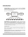
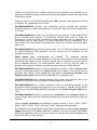
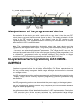
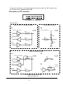
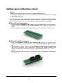
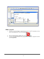
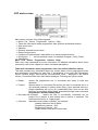
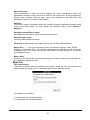
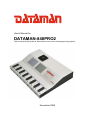
User's Manual for
DATAMAN-848PRO2
Fast universal 8x 48-pindriver Stand-Alone concurrent multiprogramming system
November 2009
COPYRIGHT © 2009
Dataman Programmers Ltd
This document is copyrighted by Dataman Programmers Ltd, United Kingdom. All rights
reserved. This document or any part of it may not be copied, reproduced or translated in
any form or in any way without the prior written permission of Dataman Programmers
Ltd.
The control program is copyrighted by Dataman Programmers Ltd. The control program
or any part of it may not be analyzed, disassembled or modified in any form, on any
medium, for any purpose.
Information provided in this manual is intended to be accurate at the time of release, but
we continuously improve all our products. Please check for an updated manual on our
website at www.dataman.com.
Dataman Programmers Ltd assumes no responsibility for misuse of this manual.
Dataman Programmers Ltd reserves the right to make changes or improvements to the
product described in this manual at any time without notice. This manual contains
names of companies, software products, etc., which may be trademarks of their
respective owners. Dataman Programmers Ltd respects those trademarks.
ZLI-0317A
2
Table of contents
Introduction .............................................................................................................................. 4
DATAMAN-848PRO2 elements............................................................................................. 6
Manipulation of the programmed device................................................................................ 7
In-system serial programming using DATAMAN-848PRO2 .................................................. 7
Selftest and calibration check .............................................................................................. 10
Technical specification......................................................................................................... 11
Programming a device........................................................................................................... 16
Engineering mode................................................................................................................ 16
Production mode.................................................................................................................. 20
Software .................................................................................................................................. 23
Detailed description of the Graphical user interface with touch screen ............................... 23
Administration of the built in PC........................................................................................... 41
Troubleshooting and warranty.............................................................................................. 46
Troubleshooting ................................................................................................................... 46
If you have an unsupported target device............................................................................ 47
Warranty terms .................................................................................................................... 48
We continuously update our manual. You may find the latest version on our website
(www.dataman.com).
Conventions used in the manual
References to the control program functions are in bold, e.g. Load, File, Device, etc.
References to control keys are written in brackets <>, e.g. <F1>.
Terminology used in the manual:
Device
ZIF socket
Buffer
USB port
HEX data format
any kind of programmable integrated circuits or programmable
devices
Zero Insertion Force socket used for insertion of the target device
part of the memory or disk used for temporary data storage
type of PC interface port
format of a data file which may be read with standard text viewers;
e.g. byte 5AH is stored as characters '5' and 'A', which means
bytes 35H and 41H. One line of this HEX file (one record) contains
the start address and data bytes. All records are secured with a
checksum.
3
Introduction
DATAMAN-848PRO2 is our extremely fast universal 8x 48-pindriver Stand-Alone
concurrent multiprogramming system designed for high volume production
programming with minimal operator effort and training. The devices are programmed at
near theoretical maximum programming speed.
Block scheme of DATAMAN-848PRO2
Windows XP Embedded
driven
high performance PC
external display
keyboard
mouse
graphics control unit
with touch screen
optional
site 1
site 2
site 3
site 4
site 5
site 6
site 7
site 8
DATAMAN-848PRO2 consists of eight independent, isolated, universal programming
modules based on the DATAMAN-48PRO2 programming hardware. The eight
individual DATAMAN-848PRO2 sockets can run asynchronously (concurrent
programming mode). Each programming module starts programming the moment the
chip is detected to be inserted into the socket correctly - independently of the status of
other programming modules. This results in seven programming modules working while
you replace the programmed chip in the eighth.
A graphical control unit with touch screen provides basic control and easy monitoring of
the programming flow.
Modular construction of hardware - the programming modules work independently – this
allows for continuing operation should a part of the circuit become inoperable. It also
makes service quick and easy.
Hands-free operation: asynchronous and concurrent operation allows a chip to begin
programming immediately upon insertion. The operator merely removes the finished
chip and inserts a new chip. Operator training is therefore minimized.
DATAMAN-848PRO2 supports all kinds and types of silicon technology found in todays
and tomorrows programmable devices, without requiring family specific modules. You
4
can be sure that new device support requires just the software to be updated and (if
necessary) a simple package converter (programming adapter), therefore the ownership
costs are minimized.
Using the built-in in-circuit serial programming (ISP) connector, the programmer is able
to program ISP capable devices in circuit.
DATAMAN-848PRO2 provides very competitive pricing coupled with excellent
hardware design for reliable programming. It is the best "value for money" programmer
in its class.
DATAMAN-848PRO2 provides very fast programming times due to high-speed FPGA
driven hardware and execution of time-critical routines taken care of inside the
programmer. At the very least, programming speeds are faster than our competitors in
this category and for many chips it is in fact much faster than our competitors. As a
result, when used in production this programmer waits for an operator and not the other
way round.
DATAMAN-848PRO2 provides two banana jacks, one for ESD wrist strap connection
for easy-to-implement ESD protection and the second one for connection of the
programmer to ground.
FPGA based totally reconfigurable 48 powerful TTL pindrivers provide
H/L/pull_up/pull_down and read capability for each pin. Advanced pindrivers incorporate
high-quality high-speed circuitry to deliver signals without overshoot or ground bounce
for all supported devices. Pin drivers operate down to 1.8V so you'll be ready to
program the full range of todays and tomorrow’s advanced low-voltage devices.
DATAMAN-848PRO2 performs on each programming module, a device insertion test
(wrong or backwards position) and contact check (poor contact pin-to-socket) before it
programs each device. These capabilities supported by overcurrent protection and
signature-byte check help prevent chip damage due to operator error.
DATAMAN-848PRO2 has a selftest capability which allows the diagnostic part of the
software to thoroughly check the health of each programming module.
DATAMAN-848PRO2 has a built-in protection circuit for eliminating damage to the
programmer and/or programmed device due to environment or operator failure. All ZIF
socket pins of the DATAMAN-848PRO2 programmer are protected against ESD up to
15kV.
DATAMAN-848PRO2 performs programming verification at the marginal levels of
supply voltage which obviously improves programming yield and guarantees long data
retention.
Various socket converters are available to handle devices in PLCC, SOIC, PSOP,
SSOP, TSOP, TSSOP, TQFP, QFN (MLF), SDIP, BGA and other packages.
It is important to remember that in most cases new devices will require only a software
update because the DATAMAN-848PRO2 is based on the truly universal (DATAMAN48PRO2) programmer. With our prompt service you can have new devices added to the
current list within a matter of days!
5
The advanced design of the DATAMAN-848PRO2 Stand-Alone multiprogramming
system, including protective circuits, original brand components and careful
manufacturing with long burning-in periods allows us to provide a three-year warranty
on parts and labor for the programmer (limited 25 000-cycle warranty on ZIF sockets).
Although we take as much care as possible to integrate high quality components for the
built-in computer, we can't provide the same level of warranty as we get from the
suppliers of computer parts. Therefore it is a limited warranty of one year for all
computer parts such as motherboard, CPU, HD, etc.
DATAMAN-848PRO2 elements
1)
2)
3)
4)
5)
6)
7)
48 pin ZIF socket
work result LEDs
power/sleep LED of site
YES! Button
ISP connector
graphical control unit with touch screen
fan grid (filter)
8)
9)
10)
11)
12)
13)
temperature controlled fans
banana jack for connection to ground
banana jack for ESD wrist strap connection
Windows XP Embedded serial number sticker
PC connectors – e.g. for display, keyboard, mouse…
power switch
6
14) power supply connector
Manipulation of the programmed device
After selection of the device you wish to work with you can insert it into the open ZIF
socket (lever is up) and close the socket (lever is down). The correct orientation of the
device in the ZIF socket is shown on the diagram near the ZIF socket on the
programmers cover. The programmed device must only be removed from the socket
when the BUSY LED is not illuminated.
Note: The programmer’s protection electronics protect the target device and the
programmer itself against either short or long-term power failures and partly against a
PC failure. However, it is not possible to guarantee the integrity of the target device due
to incorrect user-selected programming parameters. The target device may not be
destroyed by forced interruption of the control program (turning off the programmer), but
the contents of programmed cells may remain undefined. Don't remove the target
device from the ZIF socket during operations with device (BUSY LED on).
In-system serial programming DATAMAN848PRO2
Optimized advanced pindrivers deliver high programming performance without
overshoot or ground bounce for all device technologies. Pin drivers operate down to
1.8V so you'll be ready to program the full range of todays and tomorrow’s advanced
low- voltage devices.
The ISP programming solution performs programming verification at the marginal levels
of supply voltage, which obviously improves programming yield and guarantees long
data retention.
The ISP programming solution can also provide the power supply for the target system.
This ISP programming solution provides very competitive price but excellent hardware
design for reliable programming.
The software provides full and detailed information for ISP implementation: Description
of ISP connector pins for the currently selected chip, recommended target design
around the in-circuit programmed chip and other relevant information.
7
For general information, recommendations and directions about the ISP interface, see
the manual section: Common notes / ISP .
Description of ISP connector
2
4
6
8
10 12 14 16 18 20
1
3
5
7
9
11 13 15 17 19
Front view at ISP connector.
H/L/read driver
pins 3, 5, 7, 9, 11, 13 of ISP connector
A)
pin 14 of ISP connector
B)
pin of ISP
connector
drivers in programmer
drivers in programmer
pin of ISP
connector
VCC
RA1
H/L
Float
RB2
Read
RA2
Pull-up/
Pull-down
RA3
RB1
YES!
GND
pins 15, 16 of ISP connector
C)
D)
drivers in programmer
CC1
pin of ISP
connector
H/L
Float
pin of ISP
connector
RD1
RC1
GND
Read
E)
CE1
Pull-up/
Pull-down
H/L
RC2
RE1
RA1 180R, RA2 1k3, RA3 22k,
RB1 10k, RB2 10k,
8
pin of ISP
connector
CC1 1n, RC1 1k3, RC2 22k,
RD1 22k, CE1 1n, RE1 1k3,
C) Connection of pins 15 and 16 when are configured as logical signal needed for ISP
programming
D) E) when pins 15 and 16 are configured as status of LED OK and LED ERROR
D) before first action with desired ISP device
E) after first action with desired ISP device
Notes: When LED OK or LED ERROR are illuminated, this status is presented as
logical H, level of H is 1,8V - 5V depend on H level of desired ISP device.
When LED OK or LED ERROR are off, this status is presented as logical L, level of L is
0V - 0,4V.
The above mentioned values are provided to understand (and also to exactly calculate)
the value of resistors which isolate (separate) the programmed chip and target system.
The specification of the ISP connector pins depends on the selected device which you
want to work with. You can find the specification for the selected device in the control
software for the programmer (Pg4uw), menu Device / Device Info (Ctrl+F1). Note: the
ISP programming (ISP) option of the respective device must be selected. It is indicated
by the (ISP) suffix after the name of the selected device in the list.
These specifications correspond directly with application notes published by the device
manufacturers. Application notes can be found at www.dataman.com.
Note: Pin no. 1 is identified by a triangle mark on ISP cable connectors.
DATAMAN-848PRO2 ISP cable
Warnings:
• Use only the ISP cable provided. When you use other ISP cables (other material,
length…), programming may become unreliable.
• DATAMAN-848PRO2 can supply power to the programmed device (pin 1 of ISP
connector) and the target system (pin 19 and 20 of ISP connector) with some
limitations. (see Technical specification / ISP connector).
• DATAMAN-848PRO2 applies the programming voltage to the target device and
checks its value (target system can modify the programming voltage). If the
programming voltage is different from expected, no action with the target device will
be executed.
9
Selftest and calibration check
Warning:
Selftest and calibration check can be run in engineering mode only.
This mode is available only when external display, keyboard and mouse are connected
to DATAMAN-848PRO2.
If you feel that your programmer does not react according to your expectations, please
run the programmer (ISP connector’s) selftest using the Diagnostic POD (Diagnostic
POD for ISP connectors #2), which is enclosed in the standard delivery package.
Selftest of the programmer
• Insert the 48 pin diagnostic POD - type I into the ZIF socket of the programmer.
Ensure correct orientation of the 48 pin diagnostic POD - type I (see top side of
POD).
• Run the selftest of the programmer in PG4UW menu (Programmer / Selftest plus).
Selftest of the ISP connector
• Insert the Diagnostic POD for ISP connector #2 into the ZIF socket of the
programmer. Ensure correct orientation of the Diagnostic POD for ISP connector
#2.
• Interconnect the 20 pin connector of the Diagnostic POD for ISP connector #2
with the ISP connector of the programmer using the ISP cable included in the
delivery package. Ensure that the pins are interconnected properly (i.e. 1-1, 2-2, ...,
20-20).
• Run the selftest of ISP connector in the PG4UW menu (Programmer / Selftest ISP
connector…).
10
Technical specification
Specification
system)
•
•
•
•
•
(DATAMAN-848PRO2
multiprogramming
8x universal programming modules (8x 48-pin DIL ZIF sockets and 8x ISP connectors)
operation result LEDs, LED power
line power input 100-240VAC/60W max.
banana jack for ESD wrist strap connection
banana jack for connection to ground
Specification (PC system inside the programmer)
•
•
•
•
Microsoft Windows XP Embedded operation system
PC Intel Core 2 Quad 2.66 GHz
2 GB RAM
320 GB HDD
SPECIFICATION (valid for each programming module)
HARDWARE
Base unit, DACs
• USB 2.0 high-speed compatible port, up to 480 Mbit/s transfer rate
• on-board intelligence: powerful microprocessor and FPGA based state machine
• three D/A converters for VCCP, VPP1, and VPP2, controllable rise and fall time
• VCCP range 0..8V/1A
• VPP1, VPP2 range 0..26V/1A
• autocalibration/selftest
• selftest capability
Socket, pindriver
• 48-pin DIL ZIF (Zero Insertion Force) sockets accept both 300/600 mil devices up to
48-pins
• pindrivers: 48 universal
• VCCP / VPP1 / VPP2 can be connected to each pin
• perfect ground for each pin
• FPGA based TTL driver provides H, L, CLK, pull-up, pull-down on all pindriver pins
• analog pindriver output level selectable from 1.8 V up to 26V
• current limitation, overcurrent shutdown, power failure shutdown
• ESD protection on each pin of the socket (IEC1000-4-2: 15kV air, 8kV contact)
• continuity test: each pin is tested before every programming operation
ISP connector
• 20-pin male type with miss insertion lock
• 6 TTL pindrivers, provides H, L, CLK, pull-up, pull-down; level H selectable from 1.8V
up to 5V to handle all (low-voltage) devices.
11
• 1x VCCP voltage (range 2V..7V/100mA) , can be applied to two pins
• programmed chip voltage (VCCP) with both source/sink capability and voltage sense
• 1x VPP voltage (range 2V..25V/50mA)
• target system supply voltage (range 2V..6V/250mA)
• ESD protection on each pin of ISP connector (IEC1000-4-2: 15kV air, 8kV contact)
• two output signals, which indicate state of work result = LED OK and LED Error (active
level: min 1.8V)
• input signal, switch YES! equivalent (active level: max 0.8V)
DEVICE SUPPORT (valid for each programming module)
Programmer
• EPROM: NMOS/CMOS, 2708, 27xxx and 27Cxxx series, with 8/16 bit data width, full
support for LV series
• EEPROM: NMOS/CMOS, 28xxx, 28Cxxx, 27EExxx series, with 8/16 bit data width
• Flash EPROM: 28Fxxx, 29Cxxx, 29Fxxx, 29BVxxx, 29LVxxx, 29Wxxx, 49Fxxx series,
from 256Kbit to 32Mbit, with 8/16 bit data width, full support for LV series
• Serial E(E)PROM: 24Cxxx, 24Fxxx, 25Cxxx, 45Dxxx, 59Cxxx, 25Fxxx, 25Pxxx, 85xxx,
93Cxxx, NVM3060, MDAxxx series, full support for LV series
• Configuration (EE)PROM: XCFxxx, XC17xxxx, XC18Vxxx, EPCxxx, AT17xxx, 37LVxx
• 1-Wire E(E)PROM: DS1xxx, DS2xxx
• PROM: AMD, Harris, National, Philips/Signetics, Tesla, TI
• NV RAM: Dallas DSxxx, SGS/Inmos MKxxx, SIMTEK STKxxx, XICOR 2xxx, ZMD
U63x series
• PLD: Altera: MAX 3000A, MAX 7000A, MAX 7000B, MAX 7000S, MAX7000AE,MAX II
• PLD: Lattice: ispGAL22V10x, ispLSI1xxx, ispLSI1xxxEA, ispLSI2xxx, ispLSI2xxxA,
ispLSI2xxxE, ispLSI2xxxV, ispLSI2xxxVE, ispLSI2xxxVL, LC4xxxB/C/V/ZC, M4-xx/xx,
M4A3-xx/xx, M4A5-xx/xx, M4LV-xx/xx
• PLD: Xilinx: XC9500, XC9500XL, XC9500XV, CoolRunner XPLA3, CoolRunner-II
• other PLD: SPLD/CPLD series: AMI, Atmel, AMD-Vantis, Gould, Cypress, ICT, Lattice,
NS, Philips, STM, VLSI, TI
• Microcontrollers 48 series: 87x41, 87x42, 87x48, 87x49, 87x50 series
• Microcontrollers 51 series: 87xx, 87Cxxx, 87LVxx, 89Cxxx, 89Sxxx, 89LVxxx, all
manufacturers, Philips LPC series
• Microcontrollers Intel 196 series: 87C196 KB/KC/KD/KT/KR/...
• Microcontrollers Atmel AVR: AT90Sxxxx, ATtiny, ATmega series
• Microcontrollers Cypress: CY7Cxxxxx, CY8Cxxxxx
• Microcontrollers ELAN: EM78Pxxx
• Microcontrollers MDT 1xxx and 2xxx series
• Microcontrollers Microchip PICmicro: PIC10xxx, PIC12xxx, PIC16xxx, PIC17Cxxx,
PIC18xxx, PIC24xxx, dsPIC series
• Microcontrollers Motorola (Freescale): 68HC05, 68HC08, 68HC11, HCS08, HCS12
series
• Microcontrollers Myson MTV2xx, 3xx, 4xx and 5xx series
• Microcontrollers National: COP8xxx series
• Microcontrollers NEC: uPD78xxx series
• Microcontrollers Novatek: NT68xxx series
• Microcontrollers Scenix (Ubicom): SXxxx series
• Microcontrollers SGS-Thomson: ST6xx, ST7xx, ST10xx, STR7xx series
• Microcontrollers TI: MSP430 and MSC121x series
12
• Microcontrollers ZILOG: Z86/Z89xxx and Z8xxx series
• Microcontrollers other: EM Microelectronic, Fujitsu, Goal Semiconductor, Hitachi,
Holtek, Princeton, Macronix, Winbond, Infineon(Siemens), NEC, Samsung, Toshiba, ...
Notes:
• For all supported devices see full Device list at www.dataman.com
Programmer, via ISP connector
• Serial E(E)PROM: IIC series, MW series, SPI series, KEELOQ series, serial data
Flash, PLD configuration memories
• Microcontrollers Atmel: AT89Sxxx, AT90Sxxxx, ATtiny, ATmega series
• Microcontrollers Cypress: CY8C2xxxx
• Microcontrollers Elan: EM78Pxxx, EM6xxx series
• Microcontrollers EM Microelectronic: 4 and 8 bit series
• Microcontrollers Microchip PICmicro: PIC10xxx, PIC12xxx, PIC16xxx, PIC17xxx,
PIC18xxx, PIC24xxx, dsPIC series
• Microcontrollers Motorola/Freescale: HC11 series, HC908 series (both 5-wire, Allwire), HCS08, HCS12
• Microcontrollers NEC: uPD7xxx series
• Microcontrollers Philips: LPC2xxx series, LPC series, 89xxx series
• Microcontrollers Scenix (Ubicom): SXxxx series
• Microcontrollers TI: MSP430 (both JTAG and BSL series), MSC12xxx series
• PLD: Lattice: ispGAL22xV10x, ispLSI1xxxEA, ispLSI2xxxE, ispLSI2xxxV,
ispLSI2xxxVE, ispLSI2xxxVL, M4-xx/xx, M4LV-xx/xx, M4A3-xx/xx, M4A5-xx/xx,
LC4xxxB/C/V/ZC
• Various PLD (also by JAM player/JTAG support):
• Altera: MAX 3000A, MAX 7000A, MAX 7000B, MAX 7000S, MAX 9000, MAX II
• Xilinx: XC9500, XC9500XL, XC9500XV, CoolRunner XPLA3, CoolRunner-II
Notes:
For all supported devices see full Device list at www.dataman.com.
Package support
• Support for all devices in DIP with default socket
• package support includes DIP, SDIP, PLCC, JLCC, SOIC, SOP, PSOP, SSOP,
TSOP, TSOPII, TSSOP, QFP, PQFP, TQFP, VQFP, QFN (MLF), SON, BGA, EBGA,
FBGA, VFBGA, UBGA, FTBGA, LAP, CSP, SCSP etc.
• support for devices in non-DIP packages up to 48 pins with universal adapters
Programming speed
Device
Am29DL640G (parallel NOR Flash)
K8P6415UQB (parallel NOR Flash)
K9F1G08U0M (parallel NAND Flash)
QB25F640S33 (serial Flash)
AT89C51RD2 (microcontroller)
PIC32MX360F512L (microcontroller)
Size [bits]
400080Hx16 (64 Mega)
400100Hx16 (64 Mega)
8400000Hx8 (1 Giga)
800200Hx8 (64 Mega)
10000Hx8
80000Hx8
Operation
programming and verify
programming and verify
programming and verify
programming and verify
programming and verify
programming and verify
Time
24 sec
13 sec
122.7 sec
30.7 sec
14.4 sec
16.2 sec
Conditions:
PG4UW version 2.64
Notes:
• It is important to note, we always use random number patterns for programming
speed tests. Some of our competitors use a "sparse" pattern, where only some nonblank data is programmed or they use data with only a few 0 bits (FE, EF, etc.). This
13
deceptive approach can "decrease" programming times considerably. If you plan to
compare times, always ask which pattern they use.
• The programming speed depends only slightly on the PC speed.
SOFTWARE
• Algorithms: only manufacturer approved or certified algorithms are used.
• Algorithm updates: software updates are available regularly, approximately every 4
weeks, free of charge (Internet download). OnDemand versions of software are
available for high priority chip support and/or bugs fixes. There are available nearly
same day.
• Main features: revision history, session logging, on-line help, device and algorithm
information.
Device operations
• standard:
• intelligent device selection by device type, manufacturer or fragment of part name
• automatic ID-based selection of EPROM/Flash EPROM
• blank check, read, verify
• program
• erase
• configuration and security bit programming
• illegal bit test
• checksum
• interpret the Jam Standard Test and Programming Language (STAPL), JEDEC
standard JESD-71
• interpret the VME files compressed binary variation of SVF files
• security
• insertion test, reverse insertion check
• contact check
• ID byte check
• special
• production mode (automatic start immediately after device insertion)
• lots of serialization modes (more types of incremental modes, from-file data , custom
generator mode)
• statistics
• count-down mode
Buffer operations
• view/edit, find/replace
• fill/copy, move, byte swap, word/dword split
• checksum (byte, word)
• print
File load/save
• no download time because programmer is PC controlled
• automatic file type identification/recognition
14
Supported file formats
• unformatted (raw) binary
• HEX: Intel, Intel EXT, Motorola S-record, MOS, Exormax, Tektronix, ASCII-SPACEHEX, ASCII HEX
• Altera POF, JEDEC (ver. 3.0.A), e.g. from ABEL, CUPL, PALASM, TANGO PLD,
OrCAD PLD, PLD Designer ISDATA, etc.
• JAM (JEDEC STAPL Format), JBC (Jam STAPL Byte Code), STAPL (STAPL File)
JEDEC standard JESD-71
• VME (ispVME file VME2.0/VME3.0)
GENERAL
• operating voltage AC 90-264V, 47-63Hz
• power consumption max. 300W active
• dimensions 625x465x115 mm (24.6x18.3x4.5 inch)
• weight (programmer) 14.9kg (32.85 lbs)
• temperature 5°C - 35°C (41°F - 95°F)
• humidity 20%..80%, non condensing
Package included
Standard accessories
• DATAMAN-848PRO2 programmer
• diagnostic POD for ZIF socket selftest of the programmer (1x)
• diagnostic POD for ISP connector selftest of the programmer (1x)
• ISP cable (8x)
• anti-dust cover for ZIF socket (8x)
• user manual
• software
• calibration test report
• transport box
Bonus pack:
• ESD wrist strap with cord and banana plug
• Vacuum pen
• USB FLASH drive
Additional services
• free technical support (phone/fax/e-mail).
• free lifetime software update via Web site
15
Programming a device
DATAMAN-848PRO2 can operate in two modes:
Engineering mode
Production mode
for creating a project
for mass production
Engineering mode
Warning:
This mode is available only when external display, keyboard and mouse are connected
to the DATAMAN-848PRO2.
To switch to Engineering mode use File / Switch to Engineering mode.
This part of the software is focused on the quick and easy preparation of the project file
for use in the production mode of the control software.
Each programming module is driven by an easy-to-use control program with pull-down
menu, hot keys and on-line help. Selection of the device is performed by its class, by
manufacturer or simply by typing a fragment of the vendor name and/or part number. It
is the same time-proven software as used for other Dataman single-site programmers.
Engineers can use all functions of this software and can make a project for mass
production.
Standard device-related commands (read, blank check, program, verify, erase) are
boosted by some test functions (insertion test, connection check, signature-byte check),
and some other special functions (autoincrement, production mode - start immediately
after insertion of the chip into the socket).
All known data formats are supported. Automatic file format detection and conversion
are done during loading of the file. It is possible to use Jam files (JEDEC standard
JESD-71) and VME files
The rich-featured auto-increment function enables you to assign individual serial
numbers to each programmed device - or simply increment a serial number, or the
function enables you to read serial numbers or any programmed device identification
signatures from a user created file.
The software also provides a lot of information about the selected device. As an
example, the drawings of all available packages, explanation of chip labeling (the
meaning of prefixes and suffixes on the chips).
16
Make a project
1.
Connect an external display, keyboard and mouse to the PC connectors on the
back of the programmer,Turn on the programmer.
2.
3.
Run the control program: double click on the
icon.
Find the DATAMAN-848PRO2 Site (programmer): <Ctrl+F> or right click on the
panel Programmer
17
Select DATAMAN-848PRO2 site and then click on the “Connect” button.
4.
Select site.
Select desired DATAMAN-848PRO2 Site# and then click the “OK” button
5.
icon and select the desired device
Select device: click on the
18
6.
7.
Load data into the buffer from file: click on the
Set Device operation options
icon.
8.
Set desired operations for the device and then click the “OK” button
To customize device options use menu <Alt+S>
Set desired settings for the device and then click the “OK” button
19
Note: Menu Device operation options and <Alt+S> depend on the currently
selected device.
9.
Save project: click on the icon
description for the project etc.
and select the destination folder, write a
You can also make a project on other DATAMAN programmers (DATAMAN48PRO2…). For more details see Help for PG4UW or “Dataman PRO series_manual”.
The latest manual may be found at www.dataman.com.
Production mode
Note: External display, keyboard and mouse are not needed in this mode.
This part of the software is focused on the easy monitoring of high-volume production
operations via a graphical control unit with touch screen.
The user can control the following basic operations:
•
•
•
•
•
•
•
•
•
load project file
connect/disconnect programmer sites
select desired device master operation (blank check, verify, program, erase)
start/stop device operation on connected programmer sites
set some advanced options to customize available settings, for example Automatic
YES! Function
create Job report
create Problem report
copy project file(s) from external drive (for example from network drive, USB key
etc.) to the standalone's local [Projects] folder
see the progress of device operation, including statistics information, serialization...
Step by step instruction
Starting the Stand-Alone multiprogramming system
1. Check if the power switch on the back of the programmer, near power supply
connector is in position '0'.
2. Plug the power cord into the programmer’s power supply connector and turn on
the programmer using the power switch placed on the back of the programmer.
3. When the built-in computer is turned on the operating system will start bootingup, cooling fans should start to work, and the “Please Wait” screen should be
displayed on the graphical control unit.
4. Loading of the operating system can take some time, normally no longer than 1
minute.
5. After the operating system has successfully started, the Pg4uwMC control
program will start automatically. When the Pg4uwMC is ready to work the
“Welcome screen” is displayed on the graphical control unit.
6. Click the OK button on the “Welcome” screen to continue. The main screen with
menus and Status panel should appear on the graphical control unit.
20
Checking if the sites are ready to be connected
7.
When first starting the Stand-Alone multiprogramming system, or when an error
message “Programmer Sites not found” is displayed, then the programmer
software must be reinitialized by the action “Search for Programmers...”
available in the menu “Programmer / Search for Programmers...”.
8. In the dialog Search for Programmers use the button “Search” to search for
present programmer sites. The result of the search will be displayed in the table
Search results in the Search dialog. When the programmer sites are successfully
found the programmer type and its serial number is shown in the table Search
result. Detected programmers can be accepted by pressing/touching Accept. If
no complete programmer was found, then the “No Programmers found”
message will be displayed in the Search results table and the button Accept will
be disabled.
9. If the search result is “No Programmers found”, please try turning off the StandAlone programmer using menu “File / Shut down computer”, turn off the power
button on the back of programmer, wait for 15 seconds or more and start the
programmer again. If the search result is still “No Programmers found”, please
refer to the troubleshooting documentation.
Starting programmer sites
10. Each programmer site uses its own hidden control application Pg4uw.
11. To start the hidden applications of the control programmer sites, use menu
“Programmer / Connect Sites”.
12. The “Connecting sites“ indicator is displayed during connection of the sites.
Additional information about the site connection progress is displayed for each
site in the Status panel on the main screen.
13. Programmer sites are numbered from #1 to #8 in the direction of physical
placement of the programmer sites from left to right.
14. When the connection process of the programmer sites is complete, the indicator
“Connecting Sites” will be hidden. The status panel will contain information
about each site.
Loading project file
15. When the site status after connection is “Ready” or “No project file is loaded“
the user can begin the Load project operation which is accessible from the menu
File / Load project. The project file can be loaded from the default directory
[Projects] or from any other location, for example from a USB FLASH drive. For
more details about the Load project function, refer to the chapter “Menu File“ and
Load project. When the Load project operation is successful for all Sites, the
“Ready“ status must be displayed in the status panel on the touch screen for all
connected Sites. If there are some Sites with different status use the
troubleshooting documentation to resolve the problem.
Selection of predefined device operation
16. Use the menu “Device / Predefined operation“ to select the device Master
operations.
The following Master operations are available:
Blank check
Verify
Program
Erase
For more details about the predefined device operations, see chapter Menu
Device / Predefined operation.
Insertion of devices into the programmers sockets and start of device operations
21
17. Insert devices into the programmers sockets and press the Run <operation>
button on the touch screen. <operation> means predefined operation, for
example when the predefined operation is “Program device“, the caption for the
button will be “Run Program“.
18. Selected device operation including sub-operations that are part of the predefined
device operations will start. Progress of operations is displayed in the status
panel for each programmer site.
You can use the special features of the Stand-Alone multiprogramming system, for
example Count down or Statistics.
22
Software
Detailed description of Graphical user
interface with touch screen
Please Wait screen
The Please Wait screen is displayed on the standalone's built-in LCD screen as the first
screen after powering up. The screen is shown during boot up of the operating system
and launching of the standalone control software Pg4uwMC.
Welcome screen (About screen)
The Welcome screen is displayed on the Stand-Alone built-in LCD screen after
successful starting of the standalone control software. The screen can also be displayed
by using the menu command Help / About for more information see Help / About.
The Welcome screen can be closed by clicking on the OK button.
23
LCD main screen
Main screen consists of the following parts:
• Menu / File Device Programmer Options Help |
• Table with information about programmer sites (site and serialization status)
• Next serial value
• Statistics
• Recently selected device name
• Recent project name
• Checksum of data stored in data buffer for currently selected device
• Run Button... ( … can be operation name, for example Program, Verify, Erase)
• Stop Button
Menu / File Device Programmer Options Help |
Each menu item represents one menu command. For detailed information about menu
commands, refer to the chapter on menu command descriptions.
Table with information about programmer sites (site and serialization status)
This table contains key information about the current status of the programmers sites
and serialization information for each Site. If serialization is not used, the Serialization
column remains empty. Sites that are not connected, have '–' displayed in the Status
column. Connected Sites have their Status displayed. Following are typical values:
• Ready
means the programmer site is connected and ready to start any
operation
• Present
special status of connected Site means the site is connected but it is
not selected (checked in dialog Select Sites). User selected device or
project operations will not run on (unselected) Sites. User can set Site
selection in the dialog 'Select Sites' accessible through menu command
Programmer / Select Enabled Sites.
• No project file is loaded
means the Site is successfully connected but no
project file is loaded. It also means that no device is selected. The
recommended action is “Load project“.
• other text describes current status of Site(s), for example:
'Loading data from disk to buffer'
'Programming device... 85%
'Programming device... OK
'Please insert a new device into socket'
24
Next serial value
When serialization is active the panel displays the current serialization mode and
serialization number or label that will be used for the next device to be programmed.
Recent serial numbers used for each device are displayed in the table Site and
serialization status in the column Serialization.
Statistics
This panel contains information about the number of device operations processed and
actual count down status. For more details see Statistics dialog (menu Options /
Statistics).
Recently selected Device name
Manufacturer and name of any recently selected devices.
Recent Project name
Currently loaded project file name.
Checksum of data stored in the data buffer for the currently selected device.
Button Run... ( … can be the operation name, for example Program, Verify, Erase)
Clicking on the button Run... will start the selected device operation for all connected
programmer sites. The button can only be used when no device operation is running on
any programmer site.
Button Stop
Clicking on the Stop button will stop executing the currently running device operation on
all connected programmer sites.
Menu File
File / Load project
This menu command opens the dialog 'Load project', where the user can choose from
which location the project file is to be loaded and load the selected project.
Two options are available:
1. Load project from [Projects] folder...
2. Load project from another location...
25
When option 1 is selected, a dialog with a list of project files present in the [Projects]
folder will appear. The user can select the desired project and load the project by
clicking the 'Load' button. This dialog can be closed using the 'Cancel' button. Also
basic information about the selected project file can be displayed by clicking the 'File
info' button.
When option 2 is selected, a dialog with a list of project files on the specified drive and
folder will appear. The user can select the desired drive, folder and project file and load
the project by clicking on the 'Load' button. The 'Change dir' button is used to change
the current directory to the directory selected in the 'Directory' list on the left side of the
dialog. When the folder [..] is selected, the 'Change dir' button will jump up from the
current directory one level (one folder).
Note: The drive combo box is automatically refreshed each time it is dropped down. It is
useful for loading project files from a USB key which can be plugged temporarily into the
USB port of the standalone programmer and consequently the new drive letter assigned
to the USB key will appear in the list of available drives.
File / Manage projects
Manage project dialog offers two options:
1. Copy project file from another location to [Projects] folder...
2. Delete project file from [Projects] folder...
26
When option 1 is selected, the dialog with a list of project files at the specified drive and
folder will appear. The user can select the desired drive, folder and project file and copy
the selected project to the [Projects] folder by clicking on 'Copy' . The 'Change dir'
button is used to change the current directory to the directory selected in the 'Directory'
list on the left side of the dialog. When the folder [..] is selected, the 'Change dir' button
jumps from the current directory up one level (one folder).
Note: The drive combo box is automatically refreshed each time it is dropped down. It is
useful for loading project files from a USB key, which can be plugged temporarily into
the USB port of the standalone programmer and consequently the new drive letter
assigned to the USB key will appear in the list of available drives.
When option 2 is selected, the dialog with a list of project files present in the [Projects]
folder will appear. The user can select the desired project and delete the selected
project by clicking on the 'Delete' button. The dialog can be closed using the
'Cancel' button. Also basic information about the selected project file can be
displayed by clicking the 'File info' button.
File / Make Job Report...
When this menu command is selected, a Job Report will be created and displayed in
the Job Report window. Before displaying the Job Report, the information message is
displayed. The information message also contains information about the file name to
which the Job Report will be saved.
27
File / Switch to Engineering mode
This command is used to start the Pg4uw control program in Engineering mode. In this
mode the user can use the Pg4uw software to select any device from the list of
supported devices, set options for the device, load data files for device, test the device
operations on any programmer site and create a project file which can be used in
production mode. More information about Engineering mode is available in the chapter
Engineering mode.
To switch back to production mode just close the Pg4uw control program and run the
program Pg4uwMC by double-clicking on the Pg4uwMC icon on the Desktop.
Note:
Engineering mode requires connection of an external VGA monitor, keyboard and
mouse.
Do not use this menu option, without these peripherals connected and working.
File / Shut down computer
This command is used to close the control program and to shut down the built-in
computer. It is similar to the command “Shut down” found in Microsoft Windows
operating systems.
Menu Device
Device / Predefined operation
This menu allows the user to select the device Master operations. The following Master
operations are available:
• Blank check
• Verify
28
• Program
• Erase
Each Master operation can consist of a sequence of one or more partial operations, for
example the Program device operation can consist of the following sub-operations:
1.Erase
2.Program
3.Verify
Selection of the sub-operations is stored in the Project file. For details about project file
creation and usage, refer to the chapter on Engineering mode.
Preselected device operations can be started using the button Run <operation_name>
displayed on the main screen.
Menu Programmer
Programmer / Search for programmers...
This menu command displays the dialog “Search programmers”, which is used to
reinitialize the software configuration and to re-find available programmer sites. There is
no need to use this menu command in normal operation. Situations,when the command
is useful are:
1. when first starting DATAMAN-848PRO2 Stand-Alone multiprogramming system
2. when the error message “Programmer Sites not found” is displayed
In the dialog “Search Programmers” use the button “Search” to search for attached
programmers. The result of the search will be displayed in the table Search results in
the Search dialog. When the programmers sites are successfully found, the result
shows the programmer type, and allows you to accept the new settings using the button
29
Accept. Otherwise the “No Programmers found” message will be displayed in the
table Search results and the button Accept is disabled.
If the search result is “No Programmers found”, please try turning off the Stand-Alone
programmer using the menu “File / Shut down computer”, then turn off the power
button on the back of the programmer, wait for 15 seconds or more and start the
programmer again. If the search result is still “No Programmers found”, please refer to
the troubleshooting documentation.
Programmer / Connect Sites
This menu command starts the control applications for all available programmer sites.
The “Connecting Sites“ indicator is displayed during connecting of the sites. Additional
information about the site connection progress is displayed for each site in the Status
panel on the main screen.
Programmer sites are numbered from #1 to #8 in the direction of physical placment of
sites from left to right.
When the connection process is complete the indicator “Connecting Sites” will be
hidden. The Status panel will contain information about each site. The following status
information are the most common:
• Ready
means the programmer site is connected and ready to start any
operation
• Present
special status of the connected site means the site is connected but it is
also not selected (checked in the dialog Select sites). The user
selected device or project operations will not run on Present
(unselected) sites. The user can set the site selection in the dialog
'Select sites' accessible through the menu command 'Programmer /
Select Enabled sites'.
• No project file is loaded – means the site is successfully connected but no project
file is loaded. It also means that no device is selected. The
recommended action is “Load project“.
• other text describes the current status of the site(s)
Programmer / Disconnect Sites
This menu command is used to disconnect all programmer sites and close the
Programmer sites control applications. The command will apply only if no device
operation is currently running on any of the connected sites. The command does not
close the main control program. The Stand-Alone programmer and computer remains
running.
Programmer / Automatic YES!...
This command displays the dialog “Site settings” with the Automatic YES! options.
30
Three modes of Automatic YES! function are available:
• On
• Off
• Use Project settings
Automatic YES! Is always On
Automatic YES! Is always Off
Automatic YES! setting depends on the relevant settings
set and stored in the project file
When Automatic YES! mode is On the programmers sites are scanning their device
sockets after each device operation is completed. The control program can detect
removal of the programmed device and insertion of a new device and afterwards
automatically start (repeat) the recent operation on the new device. The operator does
not need to press any key or button to program the next device.
When Automatic YES! mode is Off the operation on the next device can be started
manually by pressing the YES! button near each programmer site. Each programmer
site has its own YES! button.
The status of the active Automatic YES! function is displayed on the bottom left side of
the LCD main screen with the label Automatic YES! Is On:
If the Automatic YES! function is Off, no label indicating the Automatic YES! status is
displayed.
For more details about the Automatic YES! Feature, see the chapter on Programmer /
Automatic YES! .
Programmer / Select Enabled Sites...
This command displays the dialog “Select Enabled Sites”.
31
This dialog is used to select sites that are to be used. Each site is represented by one
check box. If the check box #n is checked, it means the site #n is selected and device
operations will run on ithat site If the check box #n is unchecked, the site #n is
unselected and so no device operations will run on the Site. The sites can be set as
selected or unselected anytime this is required, except during execution of a device
operation.
Menu Options
Options / Settings...
This command displays the dialog “Settings” with a list of options that the user can
choose from and set their properties and/or settings.
Log file...
Log file settings screen looks as follows:
32
The Log file is a text file containing information about the Pg4uwMC control program
operation flow, which means information about loading project files, device operation
types and device operation results.
The main Log file name in the Stand-Alone programmer can not be modified by the
user, it has a defined value of E:\Logs\reportmc.log where drive E: is placed on the
built-in disk of the Stand-Alone programmer.
The Multiprogramming system generates a few Log files. One main Log file for program
Pg4uwMC and separate Log files for each of the running Programmer Sites. Each site
has its own Log file. The name of the site's Log file has the same prefix as the name of
the Log file specified in the edit box Log file. The file name prefix is followed by the
number of the site in the form of _#<Snum>. All Log files are placed into the folder
E:\Logs\reportmc.log where drive E: is found in the built-in disk of the standalone
programmer.
The Log file names used are:
reportmc.log
Pg4uwMC main Log file
reportmc_#1.log
Site's #1 Log file
reportmc_#2.log
Site's #2 Log file
reportmc_#3.log
Site's #3 Log file
and so on...
The following options can be set for the Log file creation:
• option Append Log file sets usage of the Log file. The Log file will be created after
the first restart of the Pg4uwMC. For all following executions of thePg4uwMC, the
existing Log file will be preserved and new data will be appended to the existing Log
file.
• option Rewrite Log file sets the usage of the Log file. The Log file will be created
after the first restart of the Pg4uwMC. For all other following executions of
Pg4uwMC, the existing Log file will be rewritten and new Log file will be created.
Data from the previous Log file will be deleted.
• Checkbox Add date information to Log file name allows the user to choose
additional date information to be included in the Log file name. When the checkbox
is checked, the program automatically adds the current date string into the Log file
name through the following rules:
If log file name has format:
< log_file_name>.<log_file_extension>
The name with added date will be:
< log_file_name><-yyyy-mmm-dd>.<log_file_extension>
33
The new part representing the date consists of yyyy - year, mmm - month and dd - day.
Example:
Log file name is E:\Logs\reportmc.log
The final log file name with added date will look like this (July, 7th, 2007):
E:\Logs\reportmc-2007-jul-07.log
Advanced options for the Log file size limit:
• option Use the Log file text truncating when the file size limit is reached - when
checked the Log file size limit is on. This means that when the Log file size
reaches the specified value, the part of the text included in the Log file will be
truncated. When the option is unchecked the size of Log file is limited by free
disk space only.
• option Maximum Log file size specifies the maximum size of the Log file in kBytes.
• option Amount of truncated text specifies the percentage of the Log file text which
will be truncated after the Maximum Log file size is reached. The higher value
means more text will be truncated (removed) from Log file.
Display settings...
The Display settings dialog contains the check box “Use invert display mode”. When
the checkbox is checked the LCD screen will be displayed in “inverted” mode.
Otherwise it will be displayed in normal mode.
Touchpad calibration...
This command is used for calibration of the built-in touch pad,which is part of the built-in
LCD touch screen.
34
The calibration of the touchpad is recommended if you encountere unexpected
reactions from the touchpad. If the user confirms the dialog about touchpad calibration
with the Yes button the calibration procedure will start. The calibration procedure will
show a blank screen with points displayed. The user has to click on the point with a
stylus. There will be sequentially displayed points at different positions. Each of the
points has to be clicked by the user. After clicking the required number of points the
touchpad calibration is complete, this will be announced by an information message.
35
Sounds...
The Dialog Sounds settings allows the user to select the sound mode of the program.
The program generates sounds after certain events, e.g. activities on device
(programming, verifying, reading, etc.). The program generates sound also when
warning or an error message is displayed. The user can now select sounds from the MS
Windows system sounds (requires installed sound card), PC speaker or No sound.
The check box “Use beep sound on touch screen press” allows switching of the beep
sound on or off. When the checkbox is checked the beep sound will be generated on
each touch screen press, that the software detects. Otherwise no beep sound will be
generated.
Options / Statistics...
This command displays the dialog “Statistics”. Statistics gives information about the
actual count of device operations which were processed on the selected type device. If
one device is corresponding to one device operation, e.g. programming, the number of
device operations will be equal to the number of programmed devices. The statistics
dialog contains the following options:
Check boxes: Program, Verify, Blank and Erase which define operations, after which
statistics values increment.
Any selected and performed device operation will increment the Total counter and one
of the Success or Failure counters depending on the device operation result (success
or failure).
A combination of partial operations is counted as one operation only. For example, a
Read operation including Verify after Read is one operation. A Program operation
including Erase and/or Verify operations is counted as one operation.
36
The next function of the statistics is Count down. Count down allows checking of the
number of device operations and then the number of devices on which device
operations have to be performed. After each successful device operation the value of
the count down counter is decremented. Count down has a user defined start number of
devices to process. When the count down value reaches zero, it means the specified
number of devices is complete and a user message about the complete count down will
be displayed.
The check box Enable Count down sets the Count down activity (enable or disable).
The edit box following the Enable Count down check box defines the initial value used
for the count down counter
.
The actual statistics values are displaying in the main window of the control program in
the Statistics panel.
Statistics panel contains:
three statistics values
two Count down information values
Good, Fail, Total.
Ctdn status and value.
Meaning of the values is as follows:
Good - number of operations which where successfully completed
Fail - number of operations which where not successfully completed
Total - number of all operations
Ctdn - informs of the Count down activity (En (enabled) or Disabled)
Remains - informs of the remaining number of device operations to do
Notes: When a project file is loaded all statistics values are set to zero and Ctdn is set
to Disabled.
For multiprogramming with the Pg4uwMC software the statistics information is also
saved to the Job Summary report.
Options / View Log...
This command displays the contents of the current Log window. At the top right corner
is the [x] button which is used for closing the Log window and displaying the main
screen.
Options / Protected mode...
Protected mode is a special mode in which to run the program. When the program is in
Protected mode there are certain program operations and commands that are
37
disabled. Protected mode is used to prevent the operator from modifying the program
or device settings. Protected mode is especially suitable or the programming of a large
amount of the same type of devices.
Protected mode can be activated using this menu option or by loading a project file that
has Protected mode activated.
Protected mode settings are saved to the configuration .ini file of the Pg4uwMC. During
the next startup of the Pg4uwMC program the Protected mode settings from the .ini file
are used.
When the Protected mode menu command is used the password dialog will appear.
The user has to enter a password twice to confirm the password is correct. After
successful password confirmation the program switches to Protected mode.
There is also one special option available - Keep "Load project" operation allowed.
The option is set to disabled as default - it means the Load project operation button and
menu will be disabled when Protected mode is active.
If the option is enabled (checked), the Load project operation button and menu will be
allowed in Protected mode.
To switch the program from Protected mode back to Normal mode, use the menu
command Options / Normal mode. The "Password required" dialog appears. The user
has to enter the same password as the password entered during the switch to Protected
mode.
When Protected mode is active, the label "Protected mode" is visible near the top of the
Status table on the main LCD screen.
Notes: Sometimes when Protected mode is switched from active state to inactive state
(Normal mode), some commands (for example command "Load project") may remain
disabled. This can be resolved by clicking the Stop button.
If the user forgets the password to turn off the Protected mode then this can be turned
off by the administrator by entering the Administrator password. Administrator login is
not necessary.
Menu Help
Help / Index
38
This menu command displays a short help on the built-in touch screen. The short help
contains brief information about menu commands and basic operations with the use of
the touch screen.
Help / Problem report...
This menu command “Create problem report” is used for writing more comprehensive
diagnostic information to the Log window and consequently copying the Log window
content to a problem report file. The Problem report is useful when an error occurs in
the control program or programmer and that the user can not resolve and must contact
Dataman support. In this case when a customer sends the request for support to
Dataman it is a good idea to send the problem report. The Problem report can help
Dataman to localize the cause of the error and resolve it sooner.
Help / Update software...
This important menu command allows users to perform software updates. After
selecting this item the program will display the question “Are you sure?”. If the user
confirms the question with Yes, the dialog “Select installation package” will be
displayed.
In this dialog the user can browse for the “pg4uward” installation package they wish to
install. The installation package can be copied beforehand to a shared Stand-Alone
folder via the network, or it can be stored on a USB FLASH drive which can be plugged
into the USB port of the Stand-Alone programmer. When a USB key is plugged into the
USB port of the programmer a new drive letter assigned to the USB key will appear in
the list of available drives in the dialog “Select installation package”. The user can
then select this drive and run the installation package from the USB key.
When the user confirms another confirmation dialog the update process will start.
During the update process the control program of the Stand-Alone programmer is
closed, thje LCD panel may be blank for some time, after installation is complete, an
39
automatic restart of the standalone programmer will be performed. The whole process
should not exceed a time of 1-2 minutes.
40
Help / About...
The welcome screen is displayed on the standalone's build-in LCD screen after
successful loading of the standalone control software. The screen can be also be
displayed using the menu command 'Help / About'. The welcome screen contains the
following basic information:
•
•
•
•
•
•
•
version of the control software currently installed
programmer type
number of Sites available
operating system
information about the processor and amount of installed RAM
computer name and IP address
system date and time
The welcome screen can be closed by clicking on the OK button.
Administration of the built in PC
Introduction
• DATAMAN-848PRO2 Stand-Alone multiprogramming system is a powerful
programmer equipped with the Windows XP Embedded operating system (“OS”).
There are two major kinds of administration of the OS – network and local. The OS
is configured with two users accounts
• admin
• operator.
Credentials for the DATAMAN-848PRO2 Stand-Alone multiprogramming system users
are:
Login
Password
Administrator admin
saadmin
Operator
operator
saoperator
Network administration
Connecting to the network
41
The OS in the programmer is configured for operating with a TCP/IP network. To obtain
the correct IP address a properly configured DHCP server must be running in your local
network during the programmers startup. After the programmer has started it will show
the “Welcome”/“About” screen. On the bottom part of the screen in the line “IP
address:” is the address obtained from the DHCP server. When the IP address is
shown as 127.0.0.1, then no network cable is connected, a DHCP server is not running
when the programmer starts or there is some other kind of problem – please refer to the
troubleshooting chapter.
Remote control
Remote administration of the DATAMAN-848PRO2 Stand-Alone multiprogramming
system is performed through the Microsoft “Remote Desktop Connection” software.
Remote desktop offers a fast and familiar way to update the software (control software
and system), and to distribute project files ...
Find and run the “Remote Desktop Connection” program on your computer. In the
“Computer” field enter the IP address shown on the “Welcome” screen of the
standalone programmer.
When communication is established, enter the administrator credentials as shown
opposite.
42
Because Windows allows only one user to be connected at a time the following
message may be displayed.
Warning: Connecting to the programmer using the remote desktop sytem at a time
when devices are being programmed will cause any actions to be immediately
terminated – your devices may not be fully programmed. Please restart the computer
after you finish remotly administering the system.
Because working through the remote desktop is similar to working on local station
please continue to read the chapter “Local administration” for help on other features
and commands.
Local administration
For local administration of the Stand-Alone programmer you must have connected a
standard PS/2 keyboard, PS/2 mouse, and standard analog display with a resolution of
at least 1024x768 and 32bit color support.
The operating disk drive is divided into three volumes. The first volume is named
“Recovery” (C:) and contains software for the OS recovery which will return the
programmer to the state as shipped from Dataman. Standard start time of the
programmer is about 2 minutes. Should the programmer not start within 10 minutes it
may be necessary to perform the OS recovery. Before going through with the operating
system recovery please connect a monitor to the programmer and report what you see
to Dataman support. For the next steps please refer to the “Operating system
43
recovery” chapter. The second volume is “System” (D:), and contains the Windows
XP Embedded operating system.
Warning: Do not delete, change files or perform any writes to the “Recovery” or
“System” disk volumes.
The third volume is named “Data” (E:). This volume contains the Programmers control
software, Projects, Logs, Updates and Temp directories.
The directory Programmer is where the main control software is installed. In the Logs
directory the log files from operations with devices are saved. When the OS update files
are available they should be saved to the Updates directory. Your project files should
be in the Projects directory. Exact update steps will be distributed along with the
operating system updates.
For programmer reliability the operating system is configured with write filters on the
“Recovery” and “System” disks. As a side effect of these filters any configuration
changes to the operating system will be lost after a restart or shutdown of the
programmer.
Operating system recovery
The Recovery OS performs a reset of the programmers operating system to a state as
it was shipped from Dataman.
Before initiating the system recovery connect a monitor to the programmer and report
what you see to the Dataman support team.
To perform the operating system recovery you must have a keyboard, mouse and
display connected to the programmer. Turn on the programmer, the BIOS screen will
show:
After this screen Windows will show the following:
44
With the arrow keys (up or down) select “Windows Recovery” and press Enter. The
recovery system will be started. Please be patient as this can take about four minutes
to complete. Then the EULA license will show.
Please read this license agreement carefully, close the window, press “A” if you accept
this agreement.
Accepting the agreement starts the formatting of disk D:, and installation of the control
program (recovery deletes the Programmer directory on disk E:, and creates a new
one). The directories Updates and Temp will also be erased and recreated. When
recovery is complete you should see the message “System recovery completed.”.
Press any key and the system will restart. The first startup of the operating system after
recovery may take a bit longer as one additional restart is performed.
45
Troubleshooting and warranty
Troubleshooting
We really want you to enjoy our product. Nevertheless, problems can occur. In such
cases please follow the instructions below.
• It might be your mistake in not properly operating the programmer or its control
program Pg4uw.
• Please read carefully all the enclosed documentation again. Probably you will find
the answer right away.
• Try to install programmer and Pg4uw on another computer. If your system works
normally on the other computer you might have a problem with the first PC.
Compare differences between both computers.
• Ask your in-house guru (every office has one!).
• Ask the person who already installed the programmer.
• If the problem persists, please call the local dealer, from whom you purchased the
programmer, or call DATAMAN direct. Most problems can be solved by email, fax or
phone.
• E-mail – Complete and submit the "TECHNICAL SUPPORT REQUEST" available
from our website www.dataman.com. Include everything that you consider being
relevant about the programmer, software and the target device.
• Mail/fax – Print and complete the "RETURNS FORM" available from our website
www.dataman.com. Include everything that you consider being relevant about the
programmer, software and the target device. Send the completed form by mail or fax
to DATAMAN (fax number in the control program, menu Help / About) or to your
local dealer.
• Phone - Call your local dealer or DATAMAN's customer support center (+44 (0)
1300 320719).
• If your programmer is diagnosed as defective, consult your local dealer or DATAMAN
about the pertinent repair center in your country. Please carefully include the following
items in the package:
• Defective product
• Completed "RETURNS FORM" available from our website www.dataman.com.
• Photocopy of a dated proof of purchase
Without all these items we cannot admit your
programmer for repair.
Note:
You may find the "DEVICE PROBLEM REPORT" form:
• at our Internet site (www.dataman.com), section Support / Problem report.
46
If you have an unsupported target device
If you need to program a target device which is not supported by the control program ,
please do not panic, follow these steps:
• Look in the device list for the latest version of the control program found on our
website Your new target device may already be included in this latest version! If it is
listed then download and install the new version of the control program.
• Contact DATAMAN directly by completing and submitting the "TECHNICAL
SUPPORT REQUEST" available from our website www.dataman.com. We may need
to request data sheets and samples of your target device. Any samples will be
returned to you after we include your target device in a new version of the Pg4uw
control software.
47
Warranty terms
The manufacturer, Dataman Programmers Ltd, gives a guarantee on failure-free
operation of the DATAMAN-848PRO2 programmer and all its parts, materials and
workmanship for three years from the date of purchase. This warranty is limited to
25,000-cycles on the DIL ZIF socket or 10,000-cycles on other ZIF sockets). Although
we take as much care as possible to integrate high quality components in the built-in
computer, we can't provide a higher warranty than we get from the suppliers. So there is
a limited warranty of one year on all computer parts such as Motherboard, CPU, HD, ...
.
If the product is diagnosed as defective, Dataman Programmers Ltd will repair or
replace the defective parts at no charge. Parts used for replacement and/or the whole
programmer are warranted for the reminder of the original warranty period only.
For repair within the warranty period, the customer must be able to prove the date of
purchase.
These warranty terms are valid for customers who purchase a programmer directly from
Dataman. The warranty conditions of Dataman resellers may differ depending on the
target country law system or the Dataman reseller’s warranty policy.
The warranty does not apply to products that are damaged through wear and tear or
mechanically damaged. Equally, the warranty does not apply to products opened and/or
repaired and/or altered by personnel not authorized by Dataman, or to products that
have been misused, abused, accidentally damaged or that were improperly installed.
For unwarrantable repairs you will be billed according to the costs of the replacement
materials, service time and carriage. Dataman or its distributors will determine whether
the defective product should be repaired or replaced and judge whether or not the
warranty applies.
Please also see the Troubleshooting section.
Manufacturer:
: Dataman Programmers Ltd
Station Road
Maiden Newton
Dorset
DT2 0AE
United Kingdom
: + 44 (0) 1300 320719
www.dataman.com, [email protected]
48