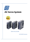
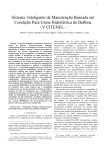
1
ABCM Symposium Series in Mechatronics - Vol. 3 - pp.679-687
c 2008 by ABCM
Copyright °
WEB SHOP FLOOR CONTROLLER FOR A FLEXIBLE
MANUFACTURING CELL
Evandro Leonardo Silva Teixeira
Autotrac Commerce and Telecommunication S/A, Department of Hardware Development (DDH), CEP
70910-901, Brasília, DF.
[email protected]
Alberto José Álvares
University of Brasilia, Department of Mechanical Engineering, Automation and Control Group (GRACO), CEP
70910-900, Brasília, DF.
[email protected]
Abstract. The aims of this work is to present the implementation’s aspects of a Web Shop Floor Controller for a
Flexible Manufacturing Cell. The FMC consist of a Turning Center ROMI Galaxy 15M, a robot manipulator ASEA
IRB6, a micrometer lazer Mitutoyo LSM-6100, an AGV and a pallet to store the blank and finished parts. The
functional model serves as a basic modeling to implement the real system. In this model are shown the internal
modules and their relationship that compound the functional modeling of the web shop floor controller. After that is
present the proposed implementation architecture based on the object oriented technology. The package and
component diagram were built considering the most important implementation aspects related to the program
language (Java technology). In results are shown the Graphical User Interface (GUI) of the Web Shop Floor
Controller implemented. This GUI’s promotes the interaction among the human operator and the FMC workstations.
Keywords:Flexible Manufacturing Cell, ShopFloor Controller, Control Systems, Client-Server Architecture, Java.
1. INTRODUCTION
Facing the new reality imposed by globalization and the concurrence, the companies are working to optimize their
production process. One of the proposed philosophy actually studied (e-manufacturing philosophy) consist into
integrate the manufacturing operations to the functional objectives of the company using the Internet resources and the
associated technology (Lee et at, 2003). This integration promotes the management of information flow among the
company hierarchical level resulting in more visibility on entire production process and promotes better definition of
the business strategy.
With the support offered by the information technology associates with the internet resources available
(instantaneous communication, sharing information, etc), besides the physical and philosophical barriers, the companies
are breaking the challenge of integrate the information flow on a unique network communication. Commercial solutions
as INM (Integrated Networked Manufacturing) and the IA (Integrated Architecture) offered by Cisco (Cisco, 2006) and
Rockwell Automation (Rockwell, 2006) respectively are some approaches that promote the integration of the
administration production systems with the company shop floor.
In this context, this paper describes the main implementation’s aspect of a Web Shop Floor Controller for a Flexible
Manufacturing Cell that uses the World Wide Web resources to promote the remote manufacturing of parts. The
Flexible Manufacturing Cell receives instructions from the Web Shop Floor Controller and convert them on the process
operations necessary to manufacture the parts.
The Web Shop Floor Controller, as a computational system, should support the production planning (on operation
planning horizon), should have functions to verify the availability of the production resources allowing the instruction
loading on the workstations, should control and monitor the production process reacting on abnormal condition that can
hinder the fulfillment of the activities established previously on the production planning.
2.FLEXIBLE MANUFACTURING CELL
The Flexible Manufacturing Cell (FMC) consists of a process unit (Turning Center Romi Galaxy 15M – CNC Fanuc
18i-ta) , a material and handling unit (ASEA IRB6 robot), a inspection unit (micrometer laser Mitutoyo LSM 6100), a
storage unit (pallet), a tool transport unit (AGV) and a control system (in this case, the Web Shop Floor Controller). The
figure 1 shows the FMC communication structure and describes the method used by the human operator to access the
FMC resources.
Hub/Switch
Internet
Hub/Switch
RS232C
r
.b
)
IP nb
P/ .u
C o
r
(T ac
.b r
gr
o.
nb .b
di
.u nb
ra
co .u
ra co
r.g ra
pe r.g
up we
lo
(F TC
O P/
C IP
A
S1
)
I/O 24V
I/O 24V
Turning Center
Micrometer Laser
AGV
I/O 24V
Communication
interface
I/O 24V
Schunk
ASEA IRB6
Figure 1. FMC communication structure.
The Turning Center (Romi Galaxy 15 M) communication is established by an Ethernet interface, using the TCP/IP
protocol, linked to the programming library (FOCAS1). The API FOCAS1 drivers and programming library promotes
the communication and programmable access to PC based on CNC System (GEFanuc, 2006). This programming library
supplies about 300 function call that can be implemented by the customer applications.
The Ethernet/Radio system is used to establish the AGV communication. This system possesses a Proxin
RangeLan2 interface to connect the robot on the computer network and to communicate with the bridge server. This
server connects the robot on the local network using the TCP/IP protocol (Álvares, et at, 2004). This configuration
mode promotes the access to the main network mechanisms and patterns (ftp, telnet, TCP/IP, sockets) and the robot can
be operated as a network workstation.
The micrometer communication is established by means of a RS232C interface. The communication process is
restricted to 23 programmed commands defined by the micrometer manufacturer (Mitutoyo). These commands promote
since the remote programming of geometric parameters (diameter and tolerances) of a part’s feature until the conditions
in which the inspection will be done.
The material and handling communication is limited to 13 digital I/O’s (7 inputs and 6 outputs). This restriction
resulted in design (in partnership with the manufacture of the Turning Center) of a dedicated interface to establish the
indirect communication with the robot based on CNC/PMC/Robot controller architecture (Teixeira, 2006).
3. GENERIC SHOP FLOOR CONTROLLER FUNCIONALITIES
The Shop Floor Controller relates management and control of the shop floor physical activities to the execution of
the production plans (Leitão, 2004). It receives the information from the upper hierarchical levels, process these
information using the heuristic approach previously defined, selects the task that must be dispatched to the shop floor
and monitors the fulfillment of the execution task. The Shop Floor Control functionalities can be subdivided in (Wysk
et at, 1995):
9
9
9
Planning;
Scheduling;
Execution task.
ShopFloor Controller
Planning
Objectives
Scheduling
Production
Orders
Information to
market
Execution tasks
Operation
Reaction to
disturbance
Monitoring
Status
Instructions
Finished
part
Raw
material
ShopFloor Plant
Figure 2. Functional model of a Generic Shop Floor Controller.
The figure 2 shows the function model of a generic Shop Floor Controller. The planning module is responsible to
select the orders that must be processed and the production resource allocated. The scheduling module defines the
sequence (according to the performance criteria selected by the operator) in which the task should be executed. The
execution task relates operation, monitor and reaction to the abnormal conditions dispatching the tasks to the shop floor,
monitoring the fulfillment of the tasks and reaction under disturbance that hinder the task execution.
4. WEB SHOP FLOOR CONTROLLER IMPLEMENTATION
Defined the Shop Floor Controller functional model, the next step consist of to design the implementation
architecture of the real system. The design of the implementation architecture must encompass the main functionality
that the real system should offer (from the human operator to the workstations). Besides to incorporate some specific
aspects of the program language selected (in this case the Java technology), the implementation architecture was built
based on object oriented technology. Therefore, this architecture can be used as a model to implement the Web
ShopFloor Controller (WSFC) using any program language that supports the object oriented technology.
4.1. Implementation architecture – Package and component diagram
The package and the component diagram of the Unified Modeling Language (UML) were used to design and to
document the implementation architecture. The WSFC modules possess their responsibility distributed on packages.
One package is a basic mechanisms used to organize and classify the elements of a group (Booch et at, 2000). Class,
interfaces and components that possess similar functionality were grouped on package.
MgU
initialization
commands
builder
model
view
controller
persistence
interfaces
Figure 3. Web Shop Floor Controller package diagram.
The figure 3 shows the WSFC package diagram. Each package is compounded by an element group that encapsulate
a particular functionality of the real system. The initialization package possesses only one class (the Initialization class).
This class has only one method (the main method) invoked every time that the WSFC is initialized. The main method is
responsible to instance the WSFC Navigator Controller.
The package Controller groups all the Controller class. Any Controller class encapsulates the logical approach of the
system. It can be classified as FrameController or LayerController class. One FrameController class listeners every user
interaction with the GUI’s, formatting and encapsulating user information to be processed while one LayerController
class manage the system navigability and the service changes among the software layers.
BuilderScheduler, BuilderDispatcher and BuilderMonitor are the main class stored on Builder package. These
classes are responsible to build the WSFC modules and their interconnections respectively. The WSFC build process
consist of to instance all the FrameController and LayerController objects that compound the WSFC modules and
connects them by means of relationships. According to Gamma (Gamma et at, 2000), the unique function of a Build
object is to create objects and complex systems. Furthermore, these objects must be destroyed after their execution task
are completed.
The Interface package groups the entire interfaces used on WFSC. One interface is a powerful mechanisms used to
reduce the degree of couple among objects. When a software layer is connected by interfaces, the modification of the
one layer do not expands to the others. Afterward, this mechanism promotes the easiest expansibility and maintenance
of the system.
The Command package groups the entire Command class. The instance of a Command class encapsulates any
request as an object, consequently, the object that invokes the operation do not need to know how the request should be
executed. For example, when the SQLInsertWorkOrder (one Command object) is initialized, it receives one
WorkOrderData object (that encapsulates the WorkOrder attributes such as due date, priority, etc). After that the
execute method is invoked, a String contain the SQL instruction is created and used to insert one new WorkOrder on the
database.
The View package aggregates the entire GUI’s developed for the WSFC. These GUI’s promotes the user interaction
to the workstations. Some customer objects, such as DateChooseButton are built considering the principle to modularize
the information (encapsulates all the common functionalities), besides to prevent the code repetition.
In the Persistence package are the entire classes that establish the communication with the external devices. The
instance of DBConnection, MicrometerConnection TurningCenterConnection, RobotConnection and AGVConnection
class establishes the connection with the database, with the micrometer, with the robot, with the Turning Center and
with the AGV respectively.
Internet
Hub/Switch
Remote
user
TC
(S P/
Q IP
L)
Hub/Switch
MgU
Server
DataBase
view JAR
controller
JAR
controller
JAR
persistence
JAR
MgU Client
model
JAR
TCP/IP
(Socket)
.br
P)
P/I unb
(TC aco.
r
g
.
io
rad
view JAR
persistence
JAR
MgU
Server
model
JAR
...
interfaces
JAR
T
(FO CP/I
CA P
S1
)
2C
23
RS
interfaces
JAR
AGV
Turning center
Micrometer
Web Shop Floor Controller
(Client Module)
Web Shop Floor Controller
(Server Module)
Figure 4. The component diagram of Web Shop Floor Controller.
ShopFloor
The figure 4 shows the component diagram of the WSFC based on the client-server architecture. The GUI’s and the
upper level functionality are available on the client module, while the lower level functionality (direct connection with
the workstations, etc) are available on the server module. The communication between these modules is established by
sockets, using the TCP/IP communication protocol.
The client (any remote user) connects to the FMC server by means of
URL :
http://webfmc.graco.unb.br/mgu/mgu.jnlp. This link points to the JNLP archive, one XML document (Extended
Markup Language) that specify how to the JAR’s archive from the client module should be downloaded to the remote
computer user. When the download of files (specified on the XML document) are finished, the WSFC is ready to be
executed.
Besides to incorporate all the advantages offered by applets (to execute the application via Web without to install it,
restriction policy, etc), the use of the Java Network Launch Protocol (JNLP) technology permits to do the incremental
download of application (JNLP, 2006). It means that every time that the application to be executed on the client
computer, only the modified JAR’s archives from the Web server will be downloaded against.
4.2 Implementation under the distributed architecture
To offer the remote access to the workstations (via Web) maintain the portability that the system should be offer,
was necessary to implement the Web Shop Floor Controller based on distributed architecture (the client-server
architecture). In this architecture, the system was designed in two modules: the client and server module. The figure 5
shows the component diagram of WSFC designed under the client-server architecture.
Web Shop Floor Controller
(Client Module)
Dispatcher
Controller
Scheduler
Controller
Persistence
ControllerInterface
TurningCenter
ControllerInterface
Monitor
Controller
Robot
ControllerInterface
Micrometer
ControllerInterface
Persis tence
Controller
TCP/IP (Socket)
Web Shop Floor Controller
(Server Module)
Persistence
Controller
JDBC API
JNI
javax.comm
cnclib.dll
WebFMC
Figure 5. Component diagram under the client-server architecture.
The client module encapsulates the upper level functionality that do not be access the directly the operational system
resources (maintain the system portability) and communicates with the logical controller of server module. In this
module, the instance of SchedulerController, DispatcherController and MonitorController class encapsulates the upper
level
functionality
(such
as
requestMasterPlanningScheduling(),
sendWorkstationCommands(),
verifyWokstationStates(), etc) and establishes the communication with the workstation’s logical controller by means of
their respective interfaces.
The server module, designed under the multithread environment, implements the upper level functionalities offered
to the client module and establishes the direct communication with the workstation controllers. In this module, the
communication with the Turning Center is established using the JNI technology (Java Native Interface). The Java
Native Interface promotes that the code executed into the JVM (Java Virtual Machine) to interact with another
applications and libraries written in other programming languages, as C, C++, etc (JNI, 2006).
Afterward, by means of this interfaces was possible that the WSFC (written in Java technology) to communicate
with the library developed in C++ (cnclib.dll) that encapsulates some programming functions offered by API FOCAS1
(used on CNC communication).
The Java Communication is the Application Programming Interface (API) used to establish the communication with
the micrometer. This API promotes the serial (RS232 interface) and parallel port (IEE-1284) port access (Java
Communication, 2006). To access the WebFMC database was used the API Java Database Connectivity (JDBC). This
API is a industrial pattern established to connect the Java technology and some databases, using the Structured Query
Language (SQL) (JDBC technology, 2006). It is necessary to maintain the Java portability and permits to change the
database without modify the server module from the WSFC.
5. RESULTS
5.1 Inspection and production planning
The inspection plan joints the information used to plan, to control and to monitor the inspection of the parts. This
plan is compounded by a set of inspection programs previously recorded on the database. Each program possess the
part’s geometry information (diameter and tolerance of each feature that will be inspected), as well as the inspection
conditions (unit system, reference, scale, etc).
The GUI InspectionPlan (figure 6) was implemented to offer the possibility to add, to edit and to delete the
inspection programs of the inspection plan. Each inspection program can be used to group until 10 feature’s geometric
information, consequently, the same production program can be used to inspect several parts without to modify the
current micrometer program, since the inspection conditions used to inspect the parts being the same.
GUI InspectionPlan
GUI ProductionPlan
Figure 6. GUI InspectionPlan and ProductionPlan.
The Master Scheduling Planning (MPS) joints the Works Orders recorded on the database. One Work Order
possesses a set of attributes (priority, due date, process time, etc) that will be used by other WSFC modules. The GUI
ProductionPlan (figure 6) was implemented, as the GUI InspectionPlan, to offer the possibility to add, to edit and to
delete the Work Orders from the database. Each work order possesses an attribute STATUS that defines the Work
Order situation for the system (To produce, In production and Produced). Therefore, to program the production the
operator should selects the Work Orders that will be produced setting the Work Order status attribute as InProduction.
5.2 Scheduling production and dispatching
Defined the production plan, the next step consist of to establish the sequence in which the Work Orders will be
manufacture. The scheduling method adopted in this work is based on priority rules (Starbek, 2003). The figure 7 shows
the GUI GanttGraph used to offer the support necessary to establish the operation sequence of the Work Orders selected
from the Production Plan.
When the operator selects the scheduling manual mode, a JDialog shows the Work Orders planned and the human
operator can scheduler the Work Orders manually. On the other hand, if the automatic mode is selected, the automatic
scheduler algorithm verify the program method (Forward or Backward) and the sequence rule (Priority, Earliest Due
Date, First In First Out or Shortest Process Time) choosed to schedule the Work Orders. The automatic scheduler
algorithm is based on the unified architecture framework collection supplied by Java 2 platform. This architecture
represents and manipulates objects collections allows that these objects could be manipulated independent their
representations (Sun Microsystem, 2006).
After to define the task list (the work order operations sequence), the human operator should have to dispatch the
task list to the workstation. This action is compounded by two phases: to verify the workstation status and to load the
task list on the workstations. The GUI VerifyWorkstationStatus (figure 7) was implemented to promote the operation
interaction necessary to verify the workstation status.
GUI Gantt Graph
GUI VerifyWorkstationStatus
Figure 7. GUI GanttGhaph and VerifyWorkstationStatus.
The WSFC communicates with each workstation to available the possibility to upload the task. While the WSFC is
checking the workstation status, a report (log) of the executed command is printed (on right side to the GUI). If any
fault occurs during the verification process, the human operator could not dispatch the task list to the workstations.
5.3 Production monitor and quality control
The VirtualMonitorFrame (figure 8) promotes the virtual monitoring of the workstations. The tab monitor (at left
side) shows the PMC tags from the Turning Center allocated to the workstation integration. On center are present the
virtual images from the workstations manufacturing a part. On right, a JPanel shows the report (log) of each occurred
event from the shop floor.
The GUI QualitControl (figure 8) promotes the human operation interaction with the quality control process. The
statistical method selected to control the process is the pre-control (Steiner, 1998) . The method’s approach is based on
three steps: to qualify the process, operation and sample frequency. The inspection of a part starts with the positioning
of the manufactured part on the micrometer’s read unit. After to position the part on the micrometer and the inspection
time programmed (DataOutputTimer) expire, the micrometer sends the inspection result to the WFSC (by RS232
interface). The response command has the following format (Mitutoyo, 2003):
Pp, (GO / NG subjugment result ) ± ddd .dddd desviation
Where:
Pp = Program Number;–NG, GO or +NG.
±ddd.ddd = Desviation value (measured value – reference).
(1)
GUI Virtual Monitor
GUI Quality Control
Figure 8. GUI Virtual Monitor and the real inspection
The program number is the geometric information from the feature inspected (diameter and tolerance). If the
judgment criteria was activated, the micrometer process unit evaluates the inspection result and check if the measured
value is inside on the tolerance limits (previously defined). The result can be –NG (if the measurement value is lower
than lower tolerance limit), G0 (if the measured is inside of tolerance limits) and +NG (if the measured value is upper
than upper tolerance limit). The figure 9 shows the virtual monitoring of the real time activity.
Virtual monitoring
Real inspection
Figure 9. Virtual monitoring and real time inspection
6. CONCLUSIONS
The Web Shop Floor controller is a computational system that uses the Internet resources to promote the remote
manufacturing of part. Besides of the portability and the remote access via Internet, the Web Shop Floor Controller
programs, controls and monitors the activity on the shop floor. The first computational version of the WSFC can be
executed from the URL: http://webfmc.graco.unb.br/mgu/mgu.jnlp. Although all the functionally are not implemented
yet, the algorithms created and the other UML diagram supplied are an important documentation for the future changes
can be done (http://webfmc.graco.unb.br/downloads/documentations).
The design and documentation of the implementation architecture using the UML diagrams result in a detailed
description, architecture centre that promotes the interactive and incremental implementation. These diagram was
designed based on object oriented technology, therefore can be applied to any object oriented programming language.
The package and component diagrams serves as a model to the future alterations could be done easiest.
The implementation based on Java technology promotes the WSFC run on the internet without to necessary to
install the application. The client must be possesses only the Java Runtime Environment (JRE) installed that support
Java 2 platform.
The implementation based on client-server architecture, encapsulates entire services that calls the operational system
functions (CNC communication and micrometer communication) on the server module. Therefore, the portability
inherited from Java technology is maintain and the WSFC can be executed on different operational systems (client
module), since the server module being installed on the Windows platform.
7. REFERENCES
Álvares, A. J. and Andriolli, G. F. and Dutra P. R. C. and Sousa, M. M. and Ferreira, J. C. E., 2004, “A navigation and
path planning system for the nomad XR4000 mobile robot with remote web monitoring”, ABCM Symposium Series
in Mechatronics, vol. 1, pp. 18-24.
Rockwell,
2006.
“Integrated
Architecture”.
16
Nov.
2006,
<
http://www.cisco.com/web/strategy/docs/manufacturing_ettf_overview0808.pdf/>
Booch, B. e Rumbaugh, J. e Jacobson, I., 2000, “UML – User guide”, ed. Campus, Rio de Janeiro, Brazil, 472p.
Cisco,
2006.
“Cisco
Ethernet
to
the
Factory”.
16
Nov.
2006,
<
http://www.rockwellautomation.com/solutions/integratedarchitecture/>
Gamma, E., Helm, R., Johnson, R. and Vlissides, J., 2000, “Design Patterns: Elements of Reusable Object-Oriented
Software”, Ed. Bookman, Porto Alegre, Rio Grande do Sul, Brazil, 364p.
GEFanuc , 2006. “Application Development - FOCAS1 (Drivers & Programming Libraries)”. 04 Sep. 2006, <
http://www.geindustrial.com/cwc/products?pnlid=2&id=cnc_mec_39>
Java Communication., 2006, “Java SE - Java Database Connectivity (JDBC)” 30 Nov. 2006, <
http://java.sun.com/javase/technologies/database/index.jsp>
JDBC technology, 2006, “Java Communications.” 21 Jul. 2006, < http://java.sun.com/products/javacomm/>
Sun
Microsystem.,
2006,
“Collections
Framework
Overview.”
25
Nov.
2006,
<
In:
http://java.sun.com/j2se/1.4.2/docs/guide/collections/overview.html>
JNI
.,
2006,
“Java
Native
Interface
Overview”.
15
Jan.
2006,
<
http://java.sun.com/j2se/1.4.2/docs/guide/jni/spec/intro.html#wp725>
JNLP
.,
2006,
“JNLP
Specification
&
API
Documentation”.
15
Jan.
2006,
<
http://java.sun.com/products/javawebstart/download-spec.html>
Lee, J., 2003. “E-manufacturing: fundamental, tools and transformation”. Robotics and Computer Integrated
Manufacturing 19, p. 501-507.
Leitão, P., 2004, “An Agile and Adaptive Holonic Architecture for Manufacturing Control”, PhD Thesis, Faculty of
Engineering, University of Porto, Portugal, 273p.
Mitutoyo, 2003, “Laser Scan Micrometer (Display Unit - LSM 6100)”. User Manual.
Starbek, M. and Kušar, J. and Brezovar, A., 2003, “Optimal Scheduling of Jobs in FMS”, Proceedings of CIRP Journal of Manufacturing Systems vol. 32, nº 5.
Steiner, S. H. 1998, “Pre-control and Some Simple Alternatives.” Quality Engineering 10, pp. 65-74.
Teixeira, E. L. S., 2006, “Development of a Managent Unit for a Flexible Manufacturing Cell integrated to a
CAD/CAPP/CAM System”, Master dissertation, Department of Mechanical Engineer, University of Brasilia, Brazil,
178p.
Wysk, R. A. and Smith, J. S., 1995, “A formal function characterization of shop floor control”, Computer Industry
Engineering, vol. 28, nº 3, pp. 631-643.
8. RESPONSIBILITY NOTICE
The authors are the only responsible for the printed material included in this paper.