1
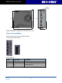
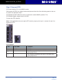
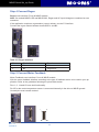
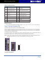
AC Servo System
Frequency
Response
3.0kHz
Quick Set-up Guide
AMP & MOONS’ Automation
MSHD Quick Set_up Guide
Important Notice
All rights reserved. No part of this work may be reproduced or transmitted in any form or by any
means without prior written permission of .
Disclaimer
The information in this manual was accurate and reliable at the time of its release. MOONS’. reserves the right to change the specifications of the product described in this manual without notice
at any time.
Trademarks
All marks in this manual are the property of their respective owners.
Customer Service
is committed to delivering quality customer service and support for all our products. Our goal is to
provide our customers with the information and resources so that they are available, without delay,
if and when they are needed.
In order to serve in the most effective way, we recommend that you contact your local sales representative for order status and delivery information, product information and literature, and application and field technical assistance. If you are unable to contact your local sales representative for
any reason, please use the most relevant of the contact details below:
For technical support, contact:
[email protected]
Part Number
For ordering the MSHD, refer to the following diagram:
MSHD - 006 - 2A
AF
1 - XX
Custom specifications
(If applicable)
Analog Input
1- One Analog input, 16bit
2- Two Analog, 14bit
Series
Rating
Cont/Peak(A)
1D5 1.5/4.5
003 3.0/9.0
4D5 4.5/18.0
006 6.0/18.0
008 8.0/28.0
010 10.0/28.0
013 13.0/28.0
Rev. 1.0
4/10/2012
Interface Options
AP- Analog/Pulse RS-232
AF- Analog/Pulse Rs-232/CANopen®/USB
EC- EtherCAT
AC Power 200V
Single Phase 115VAC(-15%~10%)50/60Hz
Single Phase 230VAC(-15%~10%)50/60Hz
Three Phase 120-240 L-L VAC +10% -15% 50/60 Hz
2
MSHD Quick Set_up Guide
Contents
Safety.........................................................................................................4
Preparation................................................................................................4
Installation Overview..................................................................................5
Step 1 Mount the MSHD............................................................................9
Step 2 Connect Motor..............................................................................10
Step 3 Connect STO................................................................................ 11
Step 4 Connect Regen ...........................................................................12
Step 5 Connect Motor Feedback.............................................................12
Step 6 Connect Controller I/Os................................................................13
Step 7 Connect Machine I/Os .................................................................15
Step 8 Connect AC Input Voltage ...........................................................17
Step 9 Set the Drive Address...................................................................19
Step 10 Connect to PC ...........................................................................19
Step 11 Install ServoStudio Software......................................................20
Step 12 Power Up....................................................................................20
Step 13 Configure the Drive....................................................................21
Drive Status.............................................................................................22
MSHD System Wiring - Pin Assignments................................................28
Contacting MOONS’................................................................................31
3
Rev. 1.0
4/10/2012
MSHD Quick Set_up Guide
Safety
Only qualified persons may perform the installation procedures. You do not need to be an expert
in motion control to install and operate the drive system. However, you must have a basic understanding of electronics, computers, mechanics, and safety practices.
The MSHD utilizes hazardous voltages.
Be sure the drive is properly grounded.
Before you install the MSHD, review the safety instructions in this manual. The manual is available
as a PDF file that can be downloaded from the MOONS’ website.
Failure to follow the safety instructions may result in personal injury or equipment damage.
Preparation
Hardware
The following hardware is required for installation.
• Mating connectors and the associated crimp pins for interfaces P1, P2, P3, and P4 (all models) and P5 (only for MSHD-008, MSHD-010 and MSHD 013).
• Mating connectors for interfaces C2, C3 and C4:
• Connector C2 (Controller I/O):
Plug 3M 10136-3000PE and shell 3M 10336-52F0-008
• Connector C3 (Machine I/O):
Plug 3M 10120-3000PE and shell 3M 10320-52F0-008
• Connector C4 (Motor Feedback):
Plug 3M 10126-3000PE and shell 3M 10326-52F0-008
• Wires for connectors:
• Connector P1: 26–28 AWG for all models.
• Connectors P2, P3, and P4:
18 AWG – for MSHD-1D5 and MSHD-003
16 AWG – for MSHD-4D5 and MSHD-006
14 AWG – for MSHD-008, MSHD-010 and MSHD-013
• Connector P5 (only for MSHD-008, MSHD-010 and MSHD-013): 16 AWG
• Connectors C2 (Controller I/O), C3 (Machine I/O) and C4 (Motor Feedback): 24–28
AWG.
• Crimping tools, if you are not using ready-made cable assemblies:
• Connector P1: Molex crimper 0638190000
• Connectors P2, P3, P4, P5: JST crimper YRF-1070.
If a crimp pin extraction tool is needed, use JST extraction tool EJ JFAJ3.
• M4 ring or spade terminal.
• A small slotted screwdriver for setting the drive address switches.
• For connection to the host computer, use one of the following:
• USB 2.0 A to Mini-B cable (USB interface)
• 4p4c plug and cable (RS232 interface)
Rev. 1.0
4/10/2012
4
MSHD Quick Set_up Guide
Computer System
The following computer system and software are required:
• 2 GHz CPU
• 1 MB RAM
• 1000 MB available on hard drive (after .net 4 is installed)
• USB port for connecting to the drive
• Operating system: Windows XP-SP3, or Windows 7
• ServoStudio, the graphical software interface for configuring and testing the drive. Download
from the MSHD product page on the Servotronix website.
• .Net4 (for details, refer to .NET Framework System Requirements). If .NET 4 is not installed
on the computer, ServoStudio will guide you through the installation, but will not install it automatically.
Installation Overview
Perform the following steps to install and setup a MSHD system. The steps are described in detail
in the following pages (See figure below).
1. Mount the MSHD.
2. Connect the motor to P2.
3. Connect safe torque off (STO) to P1, or use jumpers to bypass.
Refer to Step 3. Connect STO.
4. Connect regen resistor to pins B1+ and B2 on P3, if required.
5. Connect motor feedback to C4.
6. Connect machine I/Os to C3 and/or controller I/Os at C2.
7. Connect AC input voltage.
Note: This interface varies among models.
Refer to Step 8. Connect AC Input Voltage.
8. Set the drive address using the rotary switches.
9. Connect the drive to the PC.
10.Power up the drive and the PC.
11.Install ServoStudio software.
12.Using ServoStudio, configure and test the drive.
5
Rev. 1.0
4/10/2012
MSHD Quick Set_up Guide
MSHD Servo System Wiring
Using single-phase 230 VAC
Daisy Chain
RS232 Connection
optional connection to PC
Mains
Single-Phase
230VAC
Rotary switches
Drive addressing
Circuit Breaker
or Fuses
STO
Safe Torque Off
Connect to *24VDC
power supply OR use
bypass plug
Line Filter
(optional)
Connection to Host Controller
Connection to Additional IOs
5x digital inputs
3x digital outputs
1x fault relay
Secondary feedback
Motor Feedback
Magnetic
Contactor
*Regenerative resistor
(optional)
Voltage reference input
Pulse&Direction input
6x digital inputs
3x digital outputs
1x analog output
Ground
(Protective Earth)
Motor Power
Brake output
Motor brake
(optional)
*Relay
*24VDC power supply
Note: Refer to section EMI Suppression
in MSHD User Manual
*- To be supplied by customer
AC supply for the main power input(L1 L2) and for the logic power input(L1C L2C)
must be from the same AC phase input, as show in the diagram.
MSHD-1D5/MSHD-003 Servo System Wiring, Single-Phase 230 VAC
Rev. 1.0
4/10/2012
6
MSHD Quick Set_up Guide
Daisy Chain
RS232 Connection
optional connection to PC
Mains
Single-Phase
230VAC
Rotary switches
Drive addressing
Circuit Breaker
or Fuses
STO
Safe Torque Off
Connect to *24VDC
power supply OR use
bypass plug
Line Filter
(optional)
Connection to Host Controller
*Regenerative resistor
(optional)
Connection to Additional IOs
5x digital inputs
3x digital outputs
1x fault relay
Secondary feedback
Motor Feedback
Magnetic
Contactor
Voltage reference input
Pulse&Direction input
6x digital inputs
3x digital outputs
1x analog output
Ground
(Protective Earth)
Motor Power
Brake output
Motor brake
(optional)
*Relay
*24VDC power supply
Note: Refer to section EMI Suppression
in MSHD User Manual
*- To be supplied by customer
AC supply for the main power input(L1 L2) and for the logic power input(L1C L2C)
must be from the same AC phase input, as show in the diagram.
MSHD-4D5/MSHD-006 Servo System Wiring, Single-Phase 230 VAC
7
Rev. 1.0
4/10/2012
MSHD Quick Set_up Guide
Mains
Single-Phase
230VAC
Daisy Chain
RS232 Connection
optional connection to PC
Rotary switches
Circuit Breaker
or Fuses
Drive addressing
STO
Line Filter
Safe Torque Off
Connect to *24VDC
power supply OR use
bypass plug
(optional)
Connection to Host Controller
*Regenerative resistor
(optional)
Magnetic
Contactor
Voltage reference input
Pulse&Direction input
6x digital inputs
3x digital outputs
1x analog output
Connection to Additional IOs
Ground
(Protective Earth)
Motor Power
Motor Feedback
5x digital inputs
3x digital outputs
1x fault relay
Secondary feedback
Brake output
Motor brake
(optional)
*Relay
*24VDC power supply
Note: Refer to section EMI Suppression
in MSHD User Manual
*- To be supplied by customer
AC supply for the main power input(L1 L2) and for the logic power input(L1C L2C)
must be from the same AC phase input, as show in the diagram.
MSHD-008/MSHD-010/MSHD-013 Servo System Wiring,
Three-Phase 230 VAC
Rev. 1.0
4/10/2012
8
MSHD Quick Set_up Guide
Step 1 Mount the MSHD
Using the bracket on the back of the MSHD, mount the MSHD on a grounded conductive metal
panel.
2 Holes for
M4 of #8 Screws
164
152.4
173
150
143.7
43.2
MSHD-1D5/MSHD-003 Dimensions (in mm)
Note: MSHD-1D5 does not have fan.
M4 2p1s
(for screws M4 UN #8)
150
173
167.5
164
48.5
MSHD-4D5/MSHD-006 Dimensions (in mm)
9
Rev. 1.0
4/10/2012
MSHD Quick Set_up Guide
Φ4.5 for
Screw M4
or Imp,#8
170
195
182
185
60
MSHD-008/MSHD-10/MSHD-013 Dimensions (in mm)
Step 2 Connect Motor
Motor uses interface P2 on all MSHD models.
Connect the motor interface.
Motor Interface
Pin
1
2
3
4
Rev. 1.0
4/10/2012
Pin Label
PE
U
V
W
Function
Protective ground (motor housing)
Motor Phase U
Motor Phase V
Motor Phase W
10
MSHD Quick Set_up Guide
Step 3 Connect STO
STO uses interface P1 on all MSHD models.
Safe torque off (STO) is a safety function that prevents the drive from delivering power to the motor, which can generate torque.
STO Enable and STO Return must be connected to enable MSHD operation. The
STO Enable signal voltage must be 24 VDC.
Connect the STO interface.
Note: If the application does not require STO control, jumper pin 4 to pin 1, and pin 3 to pin 2, to
bypass the STO.
STO Interface
Pin
1
2
3
4
Pin Label
24V
GND
Function
STO Enable
STO Return
24V Return, provided by the drive for use with emergency stop circuit
24V Supply, provided by the drive for use with emergency stop circuit
11
Rev. 1.0
4/10/2012
MSHD Quick Set_up Guide
Step 4 Connect Regen
Regen uses interface P3 on all MSHD models.
Note: On models MSHD-1D5 and MSHD-003, Regen and AC Input Voltage are combined on one
connector.
If the application requires a regeneration (regen) resistor, use the P3 interface.
Connect the regen resistor between terminals B1+ and B2.
Table 3-5. Regen Interface
Pin
1
2
Pin Label
B1+
B2
Function
DC bus +
Regen bus -
Step 5 Connect Motor Feedback
Motor Feedback uses interface C4 on all MSHD models.
Wire the motor feedback interface according to the type of feedback device to be used in your application. Refer to the guidelines following the pinout table below.
Pins 1, 2, 14 and 15 have dual functionality.
Pin 25 for the motor temperature sensor is connected internally in the drive to MSHD ground.
Unused pins must remain unwired.
Rev. 1.0
4/10/2012
1
14
13
26
12
MSHD Quick Set_up Guide
Motor Feedback Interface
Pin
Function
Pin
Function
1
Incremental encoder A +
or SSI encoder data +
11
5V supply
2
Incremental encoder B +
or SSI encoder clock +
12
Motor temperature sensor
3
Incremental Encoder Z +
13
5V supply
4
Hall U +
14
Incremental encoder A or SSI encoder data -
5
Hall W +
15
Incremental encoder B or SSI encoder clock -
16
Incremental encoder Z -
17
Hall V+
24
Ground
25
Motor temperature sensor
26
Shield
Wiring Guidelines
• For incremental encoder with Halls, use pins 1, 14, 2, 15, 3, 16, 4, 17, 5, 11, 12, 24, 25, 26
Step 6 Connect Controller I/Os
Controller I/Os uses interface C2 on all MSHD models.
Wire the digital and analog inputs and outputs according to the requirements of your application.
Wire the digital and analog inputs and outputs according to the requirements of your application.
Unused pins must remain unwired.
To preserve isolation of the digital I/Os, connect a 24 VDC source to pin 19. Connect the return of
the 24 VDC supply to pin 1, which functions as the ground path for the outputs.
Note: The 24 VDC supply and return can be connected on either the Controller interface (C2) or
the Machine interface (C3), but it is not necessary to connect it on both.
1
19
18
36
Controller I/O Interface
13
Rev. 1.0
4/10/2012
MSHD Quick Set_up Guide
Pin
Function
Description
Pin
Function
Description
1
24 VDC
return
Return of the user-supplied
24 VDC
19
24 VDC
User supplied 24V, for I/O
biasing
2
Digital
output 1
Opto-isolated programmable
digital output. Read using OUT1
20
Digital
input 2
Opto-isolated programmable
digital input. Read using IN2
3
Digital
input 1
Opto-isolated programmable
digital input. Read using IN1
21
4
Equivalent
encoder
output A-
ALow side of the equivalent
encoder output signal (RS422)
22
5
Channel
B- out
Low side of the equivalent
23
encoder output signal B (RS422)
Channel
B+ out
High side of the equivalent
encoder output signal B
(RS422)
6
Channel
Z- out
Low side of the equivalent
encoder output index
(RS422)
24
Channel
Z+ out
High side of the equivalent
encoder output index (RS422)
Reserved for future use
25
Ground
Digital ground
Analog
input 1+
High side of the differential
analog command input
(±10 VDC)
26
Analog
input 1-
Low side of the differential
analog command input
(±10 VDC)
Direction
input+
High side of the direction signal
(RS422), or High side of the
master encoder signal B, or
High side of the down count
signal
Direction
input-
Low side of the direction
signal (RS422), or Low side of
the master encoder signal B,
or Low side of the down count
signal
7
8
9
27
Reserved for future use
Equivalent High side of the equivalent
encoder
encoder output signal A
output A+ (RS422)
10
Ground
Digital ground
28
Pulse
input+
High side of the pulse signal
(RS422), or High side of the
master encoder signal A, or
High side of the up count
signal
11
Pulse
input-
Low side of the pulse signal
(RS422), or Low side of the
master encoder signal A, or
Low side of the up count signal
29
Ground
Digital ground
Reserved for future use
30
12
Reserved for future use
13
Ground
Digital ground
31
Digital
input 3
Opto-isolated programmable
digital input. Read using IN3
14
Digital
input 4
Opto-isolated programmable
digital input. Read using IN4
32
Digital
input 5
Fast opto-isolated
programmable digital input.
Read using IN5
15
Digital
input 6
Fast opto-isolated programmable digital input.
Read using IN6
33
Digital
output 2
Opto-isolated programmable
digital output. Read using
OUT2
16
Digital
output 3
Fast opto-isolated programmable digital output. Read using
OUT3
34
Reserved for future use
35*
Analog
input 2-
Low side of the second
differential analog input
(±10 VDC)
High side of the second
differential analog input
(±10 VDC)
36
Analog
output
Analog output, referenced
to digital ground (0-10
VDC)
17
18*
Rev. 1.0
4/10/2012
Analog
input 2+
14
Reserved for future use
MSHD Quick Set_up Guide
Controller Interface Wiring
Step 7 Connect Machine I/Os
Machine I/Os uses interface C3 on all MSHD models.
Wire the machine inputs and outputs according to the requirements of your application.
Unused pins must remain unwired.
To preserve isolation of the digital I/Os, connect a 24 VDC source to pin 9. Connect the return of
the 24 VDC supply to pin 19, which functions as the ground path for the outputs.
Note: The 24 VDC supply and return can be connected on either the Controllerinterface (C2) or
the Machine interface (C3), but it is not necessary to connect it to both.
1
11
10
20
Machine I/O Interface
15
Rev. 1.0
4/10/2012
MSHD Quick Set_up Guide
Pin
Function
Description
Pin
1
Secondary High side of the secondary enencoder
coder input signal A (RS422), or 11
A+
High side of the pulse signal
Secondary Low side of the secondary encoder input signal A (RS422),
encoder A or Low side of the pulse、signal
2
Secondary High side of the Secondary enencoder
coder input signal B (RS422), or 12
B+
High side of the direction signal
Low side of the secondary enSecondary
coder input signal B (RS422),
encoder
or Low side of the direction
Bsignal
3
Secondary
High side of the secondary enencoder
coder input index (RS422)
Z+
13
Secondary Low side of the secondary enencoder Z- coder input index (RS422)
4
Secondary
5 VDC supply for the secondary
encoder
encoder
5V
14
Secondary Ground of the 5 VDC
encoder
supply for the secondary
ground
encoder.
5
Digital
input 7
Opto-isolated programmable
digital input. Read using IN7
15
Digital
input 8
Opto-isolated programmable
digital input. Read using IN8
6
Digital
input 9
Opto-isolated programmable
digital input. Read using IN9
16
Digital
input 10
Opto-isolated programmable
digital input. Read using IN10
7
Digital
input 11
Fast opto-isolated
programmable digital
input. Read using IN11
17
Digital
output 4
Opto-isolated programmable
digital output. Read using
OUT4
8
Digital
Opto-isolated programmable
18
digital output. Read using OUT5
Digital
output 6
Fast opto-isolated
programmable digital
output. Read using OUT6
9
output 5
User supplied 24V, for I/O
biasing
19
24 VDC
return
Return of the usersupplied
24 VDC
10
Fault relay
1
Terminal 1 of the dry contact
fault relay
20
Fault relay
2
Terminal 2 of the dry
contact fault relay
Machine Interface Wiring
Rev. 1.0
4/10/2012
16
Function
Description
MSHD Quick Set_up Guide
Step 8 Connect AC Input Voltage
Note: The AC Input interfaces and connectors vary among MSHD models.
• MSHD-1D5 and MSHD-003: One connector for bus power and logic power uses interface P3.
• MSHD-006: One connector for bus power and logic power uses interface P4.
• MSHD-013: Two connectors – a connector for bus power uses interface P4, and another connector for logic power uses interface P5.
Make the following connections:
1. Connect L1, L2 and L3 (for bus power).
• If the main voltage is from a single-phase source, connect line and neutral to L1 and L2.
• If the main voltage is from a three-phase source, connect the phases to L1, L2 and L3.
2. Connect the AC input voltage ground wire to the PE terminal, located on the MSHD front panel.
Use an M4 ring or spade terminal.
3. Connect L1C and L2C (for logic power).
• If the main voltage is from a single-phase source, connect line and neutral to L1C
and L2C.
• If the main voltage is from a three-phase source, connect any two phases to L1C
and L2C.
Make sure the main voltage rating matches the drive specification. Applying
incorrect voltage may cause drive failure.
Make sure that the AC supply for the main power input (L1 and L2), and the
logic power input (L1C and L2C) are from the same AC phase input, as shown in
Figure 3-2.
Do not apply power until all hardware connections are complete.
17
Rev. 1.0
4/10/2012
MSHD Quick Set_up Guide
AC Input Voltage Interface
Note: On models MSHD-1D5 and MSHD-003, Regen and AC Input Voltage are combined on one
connector. Since these models support only singlephase AC, they do not have a L3 terminal for
bus power.
MSHD-1D5
MSHD-003
Pin
Pin Label
Function
P3
3
4
5
6
L1
L2
L1C
LC2
AC Phase 1
AC Phase 2
Logic AC Phase 1
Logic AC Neutral
MSHD-4D5
MSHD-006
Pin
Pin Label
Function
P4
1
2
3
4
5
L1
L2
L3
L1C
LC2
AC Phase 1
AC Phase 2
AC Phase 3
Logic AC Phase 1
Logic AC Neutral
MSHD-008
MSHD-010
MSHD-013
Pin
Pin Label
Function
1
2
3
1
2
L1
L2
L3
L1C
LC2
AC Phase 1
AC Phase 2
AC Phase 3
Logic AC Phase 1
Logic AC Neutral
P4
P5
Rev. 1.0
4/10/2012
18
MSHD Quick Set_up Guide
Step 9 Set the Drive Address
Use the two rotary switches to set the drive address for both CAN and serial communication.
For Ethernet-based motion buses, the switch has no functional use for either the drive or the
network. It can be used at the application level to identify specific drives on a network.
Each switch has 10 positions:
• The upper switch positions are set as tens: 10, 20, 30 … 90
• The lower switch positions are set as ones: 0, 1, 2 … 9
Note: If two or more drives are connected to the network, address 0 cannot be used. A singular
drive may have the address 0.
Step 10 Connect to PC
To connect the drive to the host computer, use either one of the following interfaces:
• USB port. The interface is labeled C1 on all MSHD models. Use a USB 2.0 A to Mini-B cable.
19
Rev. 1.0
4/10/2012
MSHD Quick Set_up Guide
• RS232 port. The interface is labeled C7 on all MSHD models.
Use a 4p4c plug.
RS232 Interface – 4P4C
Pin
1
2
3
4
Pin Label
RX
GND ISO
TX
Function
Receive
Ground
Transmit
Unused
Step 11 Install ServoStudio Software
1. Install ServoStudio software on the host computer.
2. When installation is complete, start ServoStudio from the Windows Start menu or the shortcut
on your desktop.
Step 12 Power Up
1. After completing the hardware connections, turn on power to the drive.
Note: If logic and bus AC supplies are separate, it is recommended that logic AC be turned on
before bus AC.
2. The first time the drive is connected to the host computer on the USB port, Windows detects
the device and displays a Found New Hardware wizard.
Browse to and select the Drivers folder. The path will vary, depending on the computer’s operating
Rev. 1.0
4/10/2012
20
MSHD Quick Set_up Guide
system and the location selected for software installation; for example:
• \Program Files (x86)\\ServoStudio\Drivers
• \Program Files\\ServoStudio\Drivers
The wizard will automatically select and install the driver file STX-MSHD.inf from the
folder.
3. Look at the 7-segment display on the MSHD front panel.
Upon initial power up, the status display shows a flashing e, indicating a Parameter
Memory Checksum Failure. This fault will be cleared once the drive is configured and
the parameters are saved in the drive’s non-volatile memory.
The digital display provides various indications of drive operation, such as operation modes, drive
enable status, and fault conditions.
For more information, refer to the section Drive Status 7-Segment Display.
Step 13 Configure the Drive
1. In ServoStudio, select the Setup Wizard option from the navigation menu.
2. Follow the prompts to configure the MSHD for your particular motor and application.
Note: The wizard performs a basic drive configuration. For more advanced configuration options
and procedures, refer to the MSHD User Manual.
21
Rev. 1.0
4/10/2012
MSHD Quick Set_up Guide
Drive Status
The 7-segment display provides various indications of drive status, such as operation modes,
drive enable status, and fault conditions.
The display uses the following conventions:
• Decimal point –Enable/Disable status; if displayed, the drive is enabled.
• Steadily lit digit – Operation mode (OPMODE).
• Steadily lit letter – Warning.
• Sequential display of letters and digits – Fault.
Other Status Indications
• During the motor setup (At1) and current loop tuning (At2) procedures, three characters are
displayed in sequence.
• During the encoder initialization, a digit flashing at half-second intervals indicates the operation mode (OPMODE) currently in effect.
Normal Operation Codes
After the drive is configured and ready for operation, the display shows a steadily lit single digit,
indicating the operation mode.
Display
.
0
1
2
3
4
8
E
Name
OPMODE 0
OPMODE 1
OPMODE 2
OPMODE 3
OPMODE 4
OPMODE 8
Ember Mode
Description
Drive enabled
Serial velocity control
Analog velocity control
Serial current control
Analog current control
Master/slave gearing control
Position control
Drive is in Ember mode; firmware
is being downloaded to the drive.
Warning Codes
Warning conditions are indicated by one steadily lit character.
Display
Warning Name
Description
Action Required
F
Foldback
Drive average current
exceeds rated drive continuous current. Current
foldback is active.
Check the drive-motor sizing. This
warning can occur if the drive is
under-sized (under-powered) for
the application.
t
Over-Temperature
The temperature on the
power board and/or on
the control board has exceeded the preset limit.
Check if the ambient temperature
exceeds the drive specification.
Otherwise contact technical support.
u
Under-Voltage
The bus voltage is below Check that the main AC voltage
the minimum value.
supply is connected to the drive
and is switched on. Verify that the
setting of UVMODE is correct.
Rev. 1.0
4/10/2012
22
MSHD Quick Set_up Guide
Fault Codes
Fault conditions are indicated by one flashing character, or a sequential display of multiple characters.
The following table will help you interpret the fault codes, and respond appropriately.
• Display is the code that appears on the drive’s 7-segment display.
• Fault Name is the text message displayed in ServoStudio.
• A D indicates whether the Active Disable (controlled stop) function can be triggered by the
fault. (NA indicates Not Applicable.)
Display Fault Name
Description
AD
=
Watchdog Fault
Generally occurs due to an unNo
foreseen circumstance. The drive
is inoperable until power is cycled.
Contact technical support.
-1
Not Configured
Drive configuration required.
NA
Set drive parameters and execute CONFIG.
-5
Motor Setup Failed
Motor Setup procedure failed
(MOTORSETUPST will show the
reason)
No
Check phase and motor wiring.
Make sure to choose the correct
feedback type. And follow the
clues given in MOTORSETUPST.
-6
Current Loop Autotune Failed
One of the steps in the Current
No
Loop Autotune process has failed.
Check CLTUNEST for the failed
step.
A4
CAN Supply Fault
A problem with the internal voltage supply for the CANbus.
Yes
The drive probably needs repair.
Contact technical support.
b
Drive Locked
Security code and key do not
match. Fatal fault; drive cannot be
operated.
NA
Contact technical support.
b1
PLL (phase-locked
loop) Synchronization Failed
Controller synchronization signal
is missing or not stable. The fault
is detected only when synchronization is enabled by SYNCSOURCE command.
No
Check if controller provide synchronization signal. Check the
cable connection and wiring.
C1
CAN Heartbeat
Lost
Drive identified a disconnection in Yes
CAN master/drive connection.
Reconnect master/slave connection and power cycle the drive.
e
Parameter Memory
Checksum Failure
The non-volatile memory used to
store drive parameters is empty
or the data is corrupted.
Reconfigure the drive, or download the parameter set, and save
the parameters.
E
Failure Writing to
Flash Memory
An internal problem accessing the NA
flash memory. Fatal fault; drive
cannot be operated.
Contact technical support.
e101
FPGA Config Fail
The code for the FPGA did not
load. Fatal fault; drive cannot be
operated.
NA
Contact technical support.
e105
Self Test Fail
The power-up self test failed. Fa- NA
tal fault; drive cannot be operated.
Contact technical support.
e106
Digital EEPROM
Fault
A problem accessing the EEPROM on the digital board. Fatal
fault; drive cannot be operated.
NA
Contact technical support.
e107
Power EEPROM
Fault
A problem accessing the EEPROM on the power board. Fatal
fault; drive cannot be operated.
NA
Contact technical support.
23
NA
Action Required
Rev. 1.0
4/10/2012
MSHD Quick Set_up Guide
e108
Vbus Measure
Circuit Fail
A failure occurred in the circuit
that measures bus voltage.
Yes
Reset faults. If the fault persists,
the drive probably needs repair.
Contact technical support.
e109
Current-Sensors
Offset Out-ofRange
The calculated offsets for the current sensors are out of range.
No
Reset faults. If the fault persists,
the drive probably needs repair.
Contact technical support.
F1
Drive Foldback
Drive average current exceeds
Yes
rated drive continuous current. It
occurs after the Foldback warning
has occurred.
Check motor-drive sizing. This
warning can occur if the drive is
under-sized (under-powered) for
the application.Check that the
commutation angle is correct
(i.e., commutation is balanced)
F2
Motor Foldback
Motor average current exceeds
Yes
rated motor continuous current. It
occurs after the Foldback warning
has occurred.
Check the drive-motor sizing.
This warning can occur if the
motor is under-sized (under-powered) for the application.
H
Motor Over-Temperature
Either the motor has overheated,
or the drive is not set up correctly
for the motor temperature sensor.
Yes
Check that the drive is configured properly (using THERMODE, THERMTYPE, THERMTHRESH and THERMTIME),
and that the motor temperature
sensor is properly connected to
the drive if needed.If the drive
is configured and wired properly, check whether the motor is
under-sized for the application.
j
Velocity OverSpeed Exceeded
Actual velocity exceeded 1.2
times the velocity limit. The velocity limit is set using VLIM.
Yes
Check that VLIM is set to match
the application requirements. Using velocity loop tuning, check for
excessive overshoot.
j1
Exceeded Maximum Position Error
The position error (PE) has
exceeded the position error limit
(PEMAX)
Yes
Change drive tuning to improve
position tracking, or increase
PEMAX to allow a greater position error.
n
STO Fault
The STO signal is not connected.
No
Check that the STO connector
(P1) is wired correctly.
n1
Regen Over- Current
The preset current limit for regen
current has been exceeded.
Yes
Increase the value of the regen
resistor.
n2
Brake Fault
o
Over-Voltage
The bus voltage exceeded the
maximum value.
No
Check whether a regen resistor
is required for the application.
o15
Plus 15V Out of
Range
The internal +15 V supply is out
of range.
Yes
The drive probably needs repair.
Contact technical support.
o-15
Minus 15V Out of
Range
The internal -15 V supply is out of
range.
Yes
The drive probably needs repair.
Contact technical support.
P
Over-Current
Over current at the drive output
No
has been detected.The drive
allows this fault to occur up to 3
times in succession. After 3 faults,
the drive forces a delay of 1 minute before it can be reenabled.
Rev. 1.0
4/10/2012
Yes
24
Check for a short circuit on the
motor connection.
Check for excessive overshoot in
the current loop.
MSHD Quick Set_up Guide
r10
Sine Feedback
Communication problem between
Communication Fail the drive and the EnDat encoder.
No
Check that the data and clock
signals to the EnDat encoder are
connected properly. The cable
must be shielded.
r14
Sine Encoder
Quadrature Fault
Mismatch between calculated
and actual encoder quadrature
information.
No
Check the feedback device wiring.
Check that the correct encoder
type (MENCTYPE) is selected.
r15
Sin/Cos Calibration
Invalid
The sine/cosine calibration parameters are out of range. This
fault is related to resolver and
sine encoder feedback.
No
Re-execute the sine/cosine calibration process.
r16
Feedback 5V OverCurrent
The current supplied by the drive No
on the 5V primary encoder supply
has exceeded the preset current
limit.
The drive allows this fault to occur up to 3 times in succession.
After 3 faults, the drive forces a
delay of 1 minute before it can be
reenabled.
The MSHD can source a maximum current of 250 mA to the
primary encoder.
Check for a short-circuit at the
encoder.
Check if the encoder is drawing
more than the current limit.
r17
Secondary Feedback Index Break
Secondary encoder index line not
connected.
Yes
Check whether the drive is configured for working with the index
signal on the secondary encoder,
and check if the index signal is
connected.
r18
Secondary Feedback A/B Line
Break
One of the secondary feedback
signals is not connected.
Yes
Check that all signals from the
secondary encoder are properly
connected to the drive.
r19
Secondary Feedback 5V OverCurrent
The preset current limit for current No
supplied by the drive on the 5 V
secondary encoder supply has
been exceeded.
The MSHD can source a maximum current of 250 mA to the
secondary encoder.
Check for a short-circuit at the
encoder.
Check if the encoder is drawing
more than the current limit.
r20
Feedback Communication Error
Communication with the feedback Yes
device did not initialize correctly.
Check that the feedback device
is wired correctly.
Check that the correct encoder
type (MENCTYPE) is selected.
r21
Sanyo Encoder
Operational Fault
Communication with the Sanyo
Denki feedback device did not
initialize correctly.
Check that the feedback device
is wired correctly.
Check that the correct encoder
type (MENCTYPE) is selected.
r23
Phase Find Failed
Commutation initialization has
No
failed. This fault occurs in systems
that do not have commutation
information (e.g., Hall signals) in
the motor feedback device.
Check whether the motor feedback type and the phase-finding
parameters are set correctly for
the application.
r24
Tamagawa Init
Failed
The initialization process with the
Tamagawa feedback device has
failed.
No
Check that the wiring to the encoder is correct.
r25
Pulse & Direction
Input Line Break
One of the Pulse & Direction
signals is not connected.
No
Check that all signals to the P&D
inputs are properly connected to
the drive.
25
No
Rev. 1.0
4/10/2012
MSHD Quick Set_up Guide
r26
Tamagawa Abs
Operational Fault
Several faults are indicated by the No
feedback device and include one
or more of the following: battery
low/error, over-speed, counting
error, multi-turn error
Check the battery voltage and
feedback wiring. Make sure the
motor did not move at a high
velocity during encoder initialization.
r27
Motor Phases Disconnected
One of the motor phases is
disconnected. The current of one
of the motor phases is effectively
zero for more than 160 electrical
degrees while the current command is greater than 100.
Yes
Check the wiring of the motor
phases.
r28
Resolver Initialization Failed
The drive could not detect the
proper gain setting or sampling
point for the sine/cosine signals.
No
Check resolver wiring and gain
value.
r4
A/B Line Break
One of the primary feedback signals is not connected. This fault
occurs in incremental encoder,
resolver and sine encoder feedback types.
No
Check whether all signals from
the primary feedback device are
properly connected to the drive.
r5
Index Line Break
Encoder index line is not connected.
Yes
Check that the drive is configured for working with the index
signal (using MENCTYPE), and
check if the index signal is connected.
r6
Illegal Halls
The drive has detected either 000 Yes
or 111 state on the Hall feedback
signals.
Check that the Hall signals are
all properly connected. While
turning the motor, read the Halls
state (using HALLS) to see
which signal is not connected.
If the feedback type is Tamagawa, check that the feedback
wiring is correct
r8
A/B Out of Range
Feedback analog signal is out
of range. This fault is related to
resolver and sine encoder feedback. The drive checks that the
amplitudes of the sine and cosine
signals are correct, based on the
calculation sin2 + cos2 = 1
No
Check the amplitudes of the sine
and cosine signals.
r9
Encoder Simulation The computed equivalent encodFreq Too High
er output frequency exceeds the
upper limit for this signal, which is
4 MHz.
Yes
Check the parameters used for
setting up the equivalent encoder
output.
If using a sine encoder, check
the ENCOUTRES parameter
settings.
t1
Power Stage OverTemperature
Yes
Check if the ambient temperature exceeds the drive specification. Otherwise contact technical
support.
Rev. 1.0
4/10/2012
The temperature on the power
board has exceeded the preset
limit.
26
MSHD Quick Set_up Guide
t2
Power Module
Over-Temperature
The temperature inside the inteYes
grated power module has exceeded the preset limit.
Check if the ambient temperature exceeds the drive specification. Otherwise contact technical
support.
t3
Control Board
Over-Temperature
The temperature on the control
board has exceeded the preset
limit.
Check if the ambient temperature exceeds the drive specification. Otherwise contact technical
support.
u
Under-Voltage
The bus voltage is below the mini- No
mum value.
27
Yes
Check that the main AC voltage
supply is connected to the drive
and is switched on.
The under-voltage limit can be
read with the UVTHRESH command.
Note: Fault if flashing; warning
only if lit steadily
Rev. 1.0
4/10/2012
MSHD Quick Set_up Guide
MSHD System Wiring - Pin Assignments
Daisy Chain
C8:10 PIN
RS232
C7: 4p4c
1
2
3
4
1
19
18
36
0.1" IDC Female
NELTRON 4401-10SR OR
COXOC 304A-10PSAAA03
(STX PN CONr00000010-67
Rx
GND ISO
TX
STO
Safe Torque OFF
P1: Molex
4
(JMP to #1)
3
(JMP to #2)
2
24V RTN
1
24V STO
Mating Connector type Crimp
Housing PN 436450400
(STX PN CONr1000004-09)
4x Crimp PN 0430300001
(STX PN PINr43030000-00)
Motor
P2: JST J300
1 PE Protective Earth
2 U
U Phase
3 V
V Phase
4 W
W Phase
Mating Connector type Crimp
Housing PN F32FSS-04V-KX
(STX PN CONr10000004-13)
4x Crimp PN SF3F-71GF-P2.0
(STX PN PINrSF3F71GF-00)
1
10
Feedback
C4: MDR 26 Plug
AC Input and
Regeneration
P3: JST J300
B1+
B2
L1
L2
L1C
L2C
DC BUS +
Regen BUS AC Phase 1
AC Phase 2
Logic AC Phase 1
Logic AC Phase 2
Mating Connector type Crimp
Housing PN F32FSS-06V-KX
(STX PN CONr10000006-91)
5x Crimp PN SF3F-71GF-P2.0
(STX PN PINrSF3F71GF-00)
Mating Connector type Spring
PN 06JFAT-SBXGF-I
PE
Protective Ground
Terminal M4
* Optional, check ordering information
** Manufacturing setting
STX- MOONS’
1
14
13
26
28
Machine I/F
C3: MDR 20 Plug
11
20
1
Secondary encoder A+
11
Secondary encoder A-
2
Secondary encoder B+
12
Secondary encoder B-
3
Secondary encoder Z+
13
Secondary encoder Z-
4
Secondary encoder 5V
1 Incremental encoder A+
14 Incremental encoder A2 Incremental encoder B+
15 Incremental encoder B3 Incremental encoder Z+
16 Incremental encoder Z4 Hall U+
17 Hall V+
5 Hall W+
11 5V supply
24 Ground
12 Motor Temperature sensor
25 Motor Temperature sensor
13 5V supply
26 Shield
Mating Connector type Solder
3M solder Plug connector
PN 10126-3000PE
(STX PN CONr0000026-31)
3M solder plug Junction shell
PN 10326-52F0-008
(STX PN HODr00000026-00)
18 OUT 6
9 User supplied 24V
19 Return user supplied 24 VDC
10 Fault Relay 1
20 Fault Relay 2
Mating Connector type Solder
3M solder Plug connector
PN 10120-3000PE
(STX PN CONr0000020-28)
3M solder plug Junction shell
PN 10320-52F0-008
(STX PN HODr00000020-00)
Mating Cable
(STX PN CBLrxM900026-00
x –1,2,3 meter)
Mating Cable
(STX PN CBLrxM900020-00
x –1,2,3 meter)
Pin Assignments on MSHD-1D5/MSHD-003
Rev. 1.0
4/10/2012
1
Return user supplied 24 VDC
19
User supplied 24V
2
OUT 1
20
IN 2
3
IN 1
21
4
Equivalent encoder output A22
Equivalent encoder output A+
5
Equivalent encoder output B23
Equivalent encoder output B+
6
Equivalent encoder output Z24
Equivalent encoder output Z+
7
25
Ground
8
ANIN 1 +
26
ANIN 1 9
Direction input +
27
Direction input 10
Ground
28
Pulse input +
11
Pulse input 29
Ground
12
30
13
Ground
31
IN 3
14
IN 4
32
IN 5
15
IN 6
33
OUT 2
16
OUT 3
34
**AX417
**AX4+
35
*ANIN 2 18
*ANIN 2 +
36
ANOUT
Mating Connector type Solder
3M solder Plug connector
PN 10136-3000PE
(STX PN CONr0000036-01)
3M solder plug Junction shell
PN 10336-52F0-008
(STX PN HODr00000036-00)
Mating Cable
(STX PN CBLrxM900036-00
x –1,2,3 meter)
Mating Connector type Spring
PN 04JFAT-SBXGF-I
1
2
3
4
5
6
Controller I/F
C2: MDR 36 Plug
14
Secondary encoder GND
5
IN 7
15
IN 8
6
IN 9
16
IN 10
7
IN 11
17
OUT 4
8
OUT 5
MSHD Quick Set_up Guide
Daisy Chain
C8:10 PIN
RS232
C7: 4p4c
1
2
3
4
0.1" IDC Female
NELTRON 4401-10SR OR
COXOC 304A-10PSAAA03
(STX PN CONr00000010-67
Rx
GND ISO
TX
1
19
18
36
USB
C1: Mini-B
STO
Safe Torque OFF
P1: Molex
4
(JMP to #1)
3
(JMP to #2)
2
24V RTN
1
24V STO
Mating Connector type Crimp
Housing PN 436450400
(STX PN CONr1000004-09)
4x Crimp PN 0430300001
(STX PN PINr43030000-00)
Motor
P2: JST J300
1 PE Protective Earth
2 U
U Phase
3 V
V Phase
4 W
W Phase
Mating Connector type Crimp
Housing PN F32FSS-04V-KX
(STX PN CONr10000004-13)
4x Crimp PN SF3F-71GF-P2.0
(STX PN PINrSF3F71GF-00)
Mating Connector type Spring
PN 04JFAT-SBXGF-I
(STX PN CONr10000004-19)
1
Return user supplied 24 VDC
19
User supplied 24V
2
OUT 1
20
IN 2
3
IN 1
21
4
Equivalent encoder output A22
Equivalent encoder output A+
5
Equivalent encoder output B23
Equivalent encoder output B+
6
Equivalent encoder output Z24
Equivalent encoder output Z+
7
25
Ground
8
ANIN 1 +
26
ANIN 1 9
Direction input +
27
Direction input 10
Ground
28
Pulse input +
11
Pulse input 29
Ground
12
30
13
Ground
31
IN 3
14
IN 4
32
IN 5
15
IN 6
33
OUT 2
16
OUT 3
34
**AX417
**AX4+
35
*ANIN 2 18
*ANIN 2 +
36
ANOUT
Mating Connector type Solder
3M solder Plug connector
PN 10136-3000PE
(STX PN CONr0000036-01)
3M solder plug Junction shell
PN 10336-52F0-008
(STX PN HODr00000036-00)
Mating Cable
(STX PN CBLrxM900036-00
x –1,2,3 meter)
Regeneration
P3: JST J300
1
1 B1+
DC BUS +
2 B2
Regen BUS Mating Connector type Crimp
Housing PN F32FSS-02V-KX
(STX PN CONr10000002-10)
2x Crimp PN SF3F-71GF-P2.0
(STX PN PINrSF3F71GF-00)
10
Feedback
C4: MDR 26 Plug
Mating Connector type Spring
Not Available
AC Input
P4: JST J300
1 L1
AC Phase 1
2 L2
AC Phase 2
3 L3
AC Phase 3
4 L1C Logic AC Phase 1
5 L2C Logic AC Phase 2
Mating Connector type Crimp
Housing PN F32FSS-05V-KX
(STX PN CONr10000005-03)
5x Crimp PN SF3F-71GF-P2.0
(STX PN PINrSF3F71GF-00)
Mating Connector type Spring
PN 05JFAT-SBXGF-I
(STX PN CONr10000005-04)
Controller I/F
C2: MDR 36 Plug
1
14
13
26
PE
Protective Ground
Terminal M4
* Optional, check ordering information
** Manufacturing setting
STX- MOONS’
1 Incremental encoder A+
14 Incremental encoder A2 Incremental encoder B+
15 Incremental encoder B3 Incremental encoder Z+
16 Incremental encoder Z4 Hall U+
17 Hall V+
5 Hall W+
11 5V supply
24 Ground
12 Motor Temperature sensor
25 Motor Temperature sensor
13 5V supply
26 Shield
Mating Connector type Solder
3M solder Plug connector
PN 10126-3000PE
(STX PN CONr0000026-31)
3M solder plug Junction shell
PN 10326-52F0-008
(STX PN HODr00000026-00)
Mating Cable
(STX PN CBLrxM900026-00
x –1,2,3 meter)
Machine I/F
C3: MDR 20 Plug
11
20
1
Secondary encoder A+
11
Secondary encoder A-
2
Secondary encoder B+
12
Secondary encoder B-
3
Secondary encoder Z+
13
Secondary encoder Z-
4
Secondary encoder 5V
14
Secondary encoder GND
5
IN 7
15
IN 8
6
IN 9
16
IN 10
7
IN 11
17
OUT 4
8
OUT 5
18 OUT 6
9 User supplied 24V
19 Return user supplied 24 VDC
10 Fault Relay 1
20 Fault Relay 2
Mating Connector type Solder
3M solder Plug connector
PN 10120-3000PE
(STX PN CONr0000020-28)
3M solder plug Junction shell
PN 10320-52F0-008
(STX PN HODr00000020-00)
Mating Cable
(STX PN CBLrxM900020-00
x –1,2,3 meter)
Pin Assignments on MSHD-4D5/MSHD-006
29
Rev. 1.0
4/10/2012
MSHD Quick Set_up Guide
RS232
C7: 4p4c
1
2
3
4
Rx
GND ISO
TX
Daisy Chain
C8:10 PIN
1
19
18
36
0.1" IDC Female
NELTRON 4401-10SR OR
COXOC 304A-10PSAAA03
(STX PN CONr00000010-67
STO
Safe Torque OFF
P1: Molex
4
(JMP to #1)
3
(JMP to #2)
2
24V RTN
1
24V STO
Mating Connector type Crimp
Housing PN 436450400
(STX PN CONr1000004-09)
4x Crimp PN 0430300001
(STX PN PINr43030000-00)
Motor
P2: JST J400
1
2
3
4
PE
U
V
W
Protective Earth
U Phase
V Phase
W Phase
Mating Connector type Crimp
Housing PN J43FSS-04V-KX
(STX PN CONr10000004-18)
4x Crimp PN SJ4F-71GF-M3.0
(STX PN CRPrSJ4F71GF-00)
Regeneration
P3: JST J400
1
2
B1+
B2
DC BUS +
Regen BUS 1
10
AC Phase 1
AC Phase 2
AC Phase 3
Mating Connector type Crimp
Housing PN J43FSS-03V-KX
(STX PN CONr10000003-19 )
3x Crimp PN SJ4F-71GF-M3.0
(STX PN CRPrSJ4F71GF-00 )
Logic powerAC Input
P5: JST J300
1
2
L1C
L2C
Logic AC Phase 1
Logic AC Phase 2
Mating Connector type Crimp
Housing PN F32FSS-02V-KX
(STX PN CONr10000002-10)
2x Crimp PN SF3F-71GF-P2.0
(STX PN PINrSF3F71GF-00)
PE
Protective Ground
Terminal M4
1
14
13
26
* Optional, check ordering information
** Manufacturing setting
STX- MOONS’
20
30
1
Secondary encoder A+
11
Secondary encoder A-
2
Secondary encoder B+
12
Secondary encoder B-
3
Secondary encoder Z+
13
Secondary encoder Z-
4
Secondary encoder 5V
1 Incremental encoder A+
14 Incremental encoder A2 Incremental encoder B+
15 Incremental encoder B3 Incremental encoder Z+
16 Incremental encoder Z4 Hall U+
17 Hall V+
5 Hall W+
11 5V supply
24 Ground
12 Motor Temperature sensor
25 Motor Temperature sensor
13 5V supply
26 Shield
Mating Connector type Solder
3M solder Plug connector
PN 10126-3000PE
(STX PN CONr0000026-31)
3M solder plug Junction shell
PN 10326-52F0-008
(STX PN HODr00000026-00)
18 OUT 6
9 User supplied 24V
19 Return user supplied 24 VDC
10 Fault Relay 1
20 Fault Relay 2
Mating Connector type Solder
3M solder Plug connector
PN 10120-3000PE
(STX PN CONr0000020-28)
3M solder plug Junction shell
PN 10320-52F0-008
(STX PN HODr00000020-00)
Mating Cable
(STX PN CBLrxM900026-00
x –1,2,3 meter)
Mating Cable
(STX PN CBLrxM900020-00
x –1,2,3 meter)
Pin Assignments on MSHD-008/MSHD-010/MSHD-013
Rev. 1.0
4/10/2012
Machine I/F
C3: MDR 20 Plug
11
Feedback
C4: MDR 26 Plug
Main AC Input
P4: JST J400
L1
L2
L3
1
Return user supplied 24 VDC
19
User supplied 24V
2
OUT 1
20
IN 2
3
IN 1
21
4
Equivalent encoder output A22
Equivalent encoder output A+
5
Equivalent encoder output B23
Equivalent encoder output B+
6
Equivalent encoder output Z24
Equivalent encoder output Z+
7
25
Ground
8
ANIN 1 +
26
ANIN 1 9
Direction input +
27
Direction input 10
Ground
28
Pulse input +
11
Pulse input 29
Ground
12
30
13
Ground
31
IN 3
14
IN 4
32
IN 5
15
IN 6
33
OUT 2
16
OUT 3
34
**AX417
**AX4+
35
*ANIN 2 18
*ANIN 2 +
36
ANOUT
Mating Connector type Solder
3M solder Plug connector
PN 10136-3000PE
(STX PN CONr0000036-01)
3M solder plug Junction shell
PN 10336-52F0-008
(STX PN HODr00000036-00)
Mating Cable
(STX PN CBLrxM900036-00
x –1,2,3 meter)
Mating Connector type Crimp
Housing PN J42FSC-02V-KX
(STX PN CONr10000002-14)
2x Crimp PN SJ4F-71GF-M3.0
(STX PN CRPrSJ4F71GF-00 )
1
2
3
Controller I/F
C2: MDR 36 Plug
14
Secondary encoder GND
5
IN 7
15
IN 8
6
IN 9
16
IN 10
7
IN 11
17
OUT 4
8
OUT 5
MSHD Quick Set_up Guide
Contacting MOONS’
Service Center
+86-400-820-9661
Headquarters
No. 168 Mingjia Road Industrial Park North Minhang District Shanghai 201107, P.R. China
Tel: +86(0)21-52634688
Fax: +86(0)21-62968682
E-mail: [email protected]
MOONS' Industries (Europe) S.r.l.
Via Torri Bianche n.1 20059 Vimercate(MB) Italy
Tel: +39 039 62 60 521
Fax: +39 039 96 31 409
MOONS' Industries (South-East Asia) Pte Ltd.
33 Ubi Avenue 3 #08-23 Vertex Singapore 408868
Tel: +65 6634 1198
Fax: +65 6634 1138
Shenzhen Branch Office
Room 2209, 22/F, Kerry Center,No. 2008 Renminnan Road Shenzhen 518001 P. R.China
Tel: +86 (0)755 25472080
Fax: +86 (0)755 25472081
Beijing Branch Office
Room 202, Unit 2, 7th Building,Huilongsen International Science & Technology Industry Park,
No.99, Kechuang 14th
Street,Beijing 101111 P. R.China
Tel: +86 (0)10 59755578
Fax: +86 (0)10 59755579
Qingdao Branch Office
Room 10E, No.73 Wangjiao Mansion, mid. Hongkong Road Qingdao 266071 P. R.China
Tel: +86 (0)532 85879625
Fax: +86 (0)532 85879512
Wuhan Branch Office
Room 3001, World Trade Tower, No.686 Jiefang Avenue, Jianghan District, Wuhan 430022 P.R.China
Tel: +86 (0)27-85448742
Fax: +86 (0)27-85448355
Nanjing Branch Office
Room 302, Building A, Tengfei Creation Center,55 Jiangjun Avenue, Jiangning District,Nanjing 211100
P. R.China
Tel: +86 (0)25 52785841
Fax: +86 (0)25 52785485
31
Rev. 1.0
4/10/2012