1
UM10580
NXP Semiconductors
Mini board PCU9669
Table 1.
Jumper settings for 5 V source
Board
Jumper
DC connector
(J1, MCU board)
Slave device board
USB on MCU module
MCU board
JP1
open[1]
open[1]
open[1]
JP2
pin 2-3 short
pin 2-3 short
pin 1-2 short
JP1
short
short
short
short
if necessary[2]
9669 board
9665 board
necessary[2]
JP2
if
JP3
short
short
JP4
open
open
JP1
if
necessary[2]
short
if necessary[2]
JP2
short
short
short
JP3
if necessary[2]
short
if necessary[2]
[1]
The jumper pin JP1 on the MCU board should be always open while the MCU module is supplying 3.3 V.
3.3 V is not available when the LPCXpresso is used without LPC-link (JTAG debugger portion). In this case,
short the JP1 (on the MCU board) to supply the 3.3 V from the regulator on the MCU board.
[2]
Be careful to prevent supply conflict. Also, when supplying to slave boards be sure that there is enough
power capacity for all the slave boards that are attached.
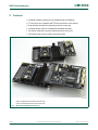
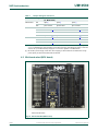
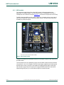
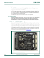
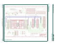
4.2 Mini board mbed (MCU board)
019aac765
MCU board with mbed.
Fig 24. Mini board MCU (MCU board)
UM10580
User manual
All information provided in this document is subject to legal disclaimers.
Rev. 1 — 25 February 2014
© NXP B.V. 2014. All rights reserved.
19 of 57