1
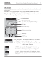
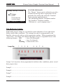
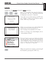
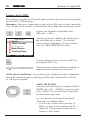
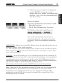
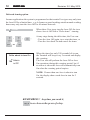
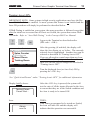
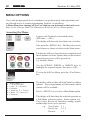
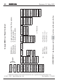
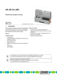
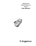
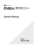
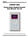
CONCEPT 4000. Prisma Colour Graphic Terminal User Manual. CONCEPT 4000 Prisma Colour Graphic T erminal Terminal User Manual. R ev 2.0 Rev NOTE: This User Manual is intended to be read in conjunction with the Concept 4000 User Manual which describes many additional User operations. 1 CONCEPT 4000. 2 Revision 2.0 May 2012. CONTENTS The Keypad. .......................................................................................... 3 Default LCD Display ............................................................................. 6 Indicator Lamps. ................................................................................... 7 If Used. [ ] [ ] [ ] [ ] [ ] [ ] [ ] [ ] USER ALARM SYSTEM OPERATIONS ........................................ Level Messages. ..................................................................................... Logging On. .......................................................................................... Turning Area/s OFF. ............................................................................. Deferred Arming ................................................................................... Turning Area/s ON................................................................................ Activating a Panic Alarm. ..................................................................... Activating a Duress Alarm.................................................................... Acknowledge an Alarm. ........................................................................ 8 8 9 10 12 13 15 15 16 USER ACCESS CONTROL OPERATIONS.................................... 17 [ ] USER SYSTEM STATUS & CONTROL OPERATIONS .............. View Alarm Review information. ......................................................... View System Information. ..................................................................... Home Auxiliary Control. ....................................................................... [ ] [ ] MENU OPTIONS ................................................................................ 22 Accessing the Menu. ............................................................................. 22 Keypad Functions in the Menu. ............................................................ 23 [ ] 18 18 19 20 CONCEPT 4000 USER MENU FLOWCHART .............................. 24 INNER RANGE recommends that all CONCEPT systems are installed & maintained by FACTORY CERTIFIED TECHNICIANS. For a list of Accredited Dealers in your area refer to the Inner Range Website. http://www.innerrange.com Disclaimer While every effort has been made to ensure the accuracy of this manual, the manufacturer and/ or it’s agents assume no responsibility or liability for any errors or omissions. Due to ongoing development and product improvements, the contents of this manual are subject to change without notice. CONCEPT 4000. Prisma Colour Graphic Terminal User Manual. 3 The Keypad. Operations & programming are performed by using the function keys, fixed keys and scroll wheel. Each time a key is pressed, a short “beep” will be emitted to indicate that the key press was accepted. (The Installer can disable the beeping if necessary) If the Terminal emits a long “beep”, it means that the key press was not accepted or is not allowed. You may only press one key at a time. Function keys Scroll wheel and up, down, left, & right arrow keys OK key ON / OFF keys Alpha-numeric keys END key HELP key FUNCTION KEYS. The operation of these keys will change according to the screen currently in use. e.g. Left Key: Menu / Text Menu / Cancel / Exit Right Key: Log On / Config / Delete / Area Lists / 24Hour / Areas / Timed On <MENU>. Accesses the Menu for information and operations other than Area On/Off, Door Access, etc. A limited Menu will be displayed if you are not logged on. <Cancel>. Allows you to cancel a PIN code entry without logging an attempt. e.g. If you make a mistake and want to start again. 4 CONCEPT 4000. Revision 2.0 May 2012. <Text Menu>. Once in the Menu, allows you to switch between an Iconic menu and a Text menu. Due to limited screen space for display of icons, the text menu usually offers additionl menu options. <Exit>. Exit to the default display. <Log On>. Displays the Logon screen. <Config>. Once in the Menu, allows access to the userconfigurable Prisma Terminal options such as colour schemes, backlight levels and speaker volume, etc. The “Config” function key will only be displayed for Users with permission for the “Users”, “Access” or “Times” Menus. <Delete>. Allows you to delete the last character entered. e.g. If you make a mistake while entering your PIN code. <Area Lists> / <24 Hour> / <Areas>. When in the Area control screen, alternative Area control options will be presented on the right-hand Function key. Note: “24 Hour” allows the Tamper monitoring part of the Area to be turned ON or OFF (Normally restricted to Installer &/or Owner) ARROW KEYS AND SCROLL WHEEL. The SCROLL WHEEL or the <UP> and <DOWN> arrow keys are used to scroll up and down through lists of available items to view, control or program (e.g. Areas, Zones, Review messages, etc), and to adjust numerical values (e.g. Home Auxiliary Timer). The Scroll Wheel can also be used to move the cursor left or right. The <LEFT> arrow key will move the cursor to the left. The <RIGHT> arrow key will move the cursor to the right OR if pressed when not logged on, may display Home Auxiliary control options if enabled. CONCEPT 4000. Prisma Colour Graphic Terminal User Manual. 5 The <OK> key must always be pressed after you have entered your secret PIN code (Unless performing a “Quick Arm or Disarm” operation). You have 10 seconds to press the <OK> key after you have completed entering the code. If PIN codes are used to unlock doors, pressing the <OK> key again will perform the Door unlock operation on the Door associated with the Terminal. On Terminals that are programmed ONLY for Door Access control, the <OK> key may not need to be pressed twice. (In some cases, the <OK> key may be programmed to unlock a door without a PIN code being used. e.g. In low security periods, or when the Terminal is on the inside of an Exit Door.) OFF / ON. Used to turn Off or turn On, the Item named on the Display at the time. e.g. Area, Area List, Home Auxiliary, etc. ALPHA-NUMERIC keys. Used for entering your secret PIN code. You have 10 seconds to enter each digit, and must press the <OK> key when complete. This sequence is required before most panel operations can be performed. These keys can also be used to search for an item to be controlled by selecting the first letter of it’s name. HELP. Can be pressed at any time and displays a “Help message” about the current operation being performed. The <END> key is used when you have finished performing the required operations. NOTE: Keypad keys also have other functions when you are selecting, viewing, controlling or programming items in the menu. Details of the keypad functions when you are in the menu are provided in the “Menu Options” section of this manual. The system may be programmed to limit the operations available at some Terminals. 6 CONCEPT 4000. Revision 2.0 May 2012. Default LCD Display. The Prisma Terminal offers a number of options for the Default display. This is the display that will be shown when there are no User operations being performed, and no Alarms or other messages to be displayed. The Default display can be selected separately for each Terminal in your system. The settings can only be programmed by the Installer, who can also advise you on the appropriate options. If no specific Default Display option has been chosen, the Concept 4000 logo will be displayed. SINGLE AREA STATUS. This option allows the name and current status of a single Area to be displayed. This is useful when the Terminal only provides control of one Area. Library is Off Menu Temp 25.3°C Log On Admin Kitchen Bistro Public Bar Bottle Shop Cellar Cool Room Band Room Menu Log On Monday, 18th Apr 11:25am Library is Off MULTIPLE AREA STATUS. The Multiple Area status screen allows the current status of 8 Areas to be viewed by name. The icon against each Area name indicates the current status; Off (Disarmed), On (Armed), Timed Off (Defer Arming timer running) or Defer Warning (Timer about to expire). See “Turning Areas Off” for details of the Defer Arming feature. TIME & DATE. Allows the current system Time & Date to be displayed. This is useful in systems that generate Time-On-Site reports, providing a display of the actual system Date & Time being logged. Time & Date display is at the bottom of the screen if the Multiple Area Status option is selected. CONCEPT 4000. Prisma Colour Graphic Terminal User Manual. CUSTOM MESSAGE. The “Diaries” feature can be utilized to provide a customized message that is appropriate for the particular Site and/or the particular Terminal. Some common applications are: -The Monitoring Station’s Telephone number. -The Installer’s Telephone number. -“Welcome to <your company name>”. Monday, 18th Apr 11:25am Library is Off Concept Security by Inner Range Menu Temp 25.3°C Log On The Indicator Lamps. Eight multi purpose lamps are provided for quick indication of Area and Alarm Status, and/or other conditions. The settings can only be programmed by the Installer, who can also advise on the appropriate options. When programmed for “Area Array”, the lamps will indicate the status of up to 8 sequential Areas in the following manner: Off = Area Off (Disarmed) On = Area On (Armed) Flashing = Alarm in this Area. Lamp No: 1 2 7 3 4 5 6 7 8 Lamps 5 to 8 may have been programmed to indicate other conditions, please record their purpose here: Lamp 5 .............................................................................................................. Lamp 6 .............................................................................................................. Lamp 7 .............................................................................................................. . Lamp 8 .............................................................................................................. . 8 CONCEPT 4000. Revision 2.0 May 2012. USER OPERATIONS User operations are the basic day-to-day operations performed on the system. These include: Turning Areas ON and OFF. (Arming and Disarming) Acknowledging Alarm messages. Accessing Doors and/or Lifts Viewing “Alarm Review” information and Area Status. Controlling Outputs (Turning Home Auxiliaries ON and OFF) The system has been designed for simple operation, providing straightforward procedures, and display prompts in plain English text. However, if a User is unsure of what to do next, a simple press of the <HELP> key provides additional assistance. Most User operations begin with the same simple procedure. The User must LOGON to the Terminal by entering their secret PIN code followed by the <OK> key. When this is done, the system verifies the User and depending on the operations allowed, the User is then able to select another key to press to perform the operation required. The LOGON procedure is described on the following page. Common operations are then described in detail. Level Messages. System operation is continuously monitored for problems and special conditions. A “Level Message” is displayed on one or more of the Terminal/s if such a condition exists and will remain on the LCD display until the condition is rectified. * You will probably need the Installer to rectify any of the first 4 conditions. MESSAGE DESCRIPTION Had Power Problem* One or more Modules have lost AC power. If accessible, check AC power cord/plug- pack is connected & switched on. Had Battery Problem* One or more Modules have low battery voltage. Had Network Problem* One or more Modules are not communicating with the Control Module. There may be cable damage or a Module problem. Had Comms Problem* There is a problem with one or more Comms Tasks. e.g. Central Station, PC, Printer, etc. Alarm re porting may be compromis e d. Some Inputs latched/isolated See "Acknowledge Latched Alarms" and "View Input States” in the /tampered/unsealed. Concept 4000 User Manual . <MENU>, <1>, <5>. Area about to turn On See “Turning Area/s Off”. Deferred Area Arming Option. Area Name, Enter Code See “Menu Group Options”. [C]ancel Holdup in the Concept 4000 User Manual. CONCEPT 4000. Prisma Colour Graphic Terminal User Manual. 9 LOGON LOGON. Logging on is the first step performed in MOST operations. - Enter your secret PIN Code using the digit keys, then press the <OK> key. Each digit pressed will be displayed as an asterix (*) character. , User code entry Enter your PIN If you make an error while entering your PIN code, press <Delete> to delete the last character entered, or the <END> key to start again. ******** Cancel OK=Accept Delete Good Morning Polly Nomial If there are no messages to be acknowledged, the Display may first greet and identify you. Note: Greeting can be disabled in V3 or later. If there is a message to be acknowledged, refer to “Acknowledge an Alarm”. Area Control Admin Sales Counter Warehouse Board Room Training Room Menu Press On The Area Control screen is now displayed, with the first Area (or Area List) that you are allowed to control highlighted, and a text prompt for the relevant action on that Area, shown at the bottom of the screen. i.e. “Press On” or “Press Off”. Area Lists When your operations are complete, you must Logoff the Terminal by pressing the <END> key. 10 CONCEPT 4000. Revision 2.0 May 2012. Turning Area/s OFF. Once you have Logged on to a Terminal, and can view the Area status, you may perform the Area OFF or ON operations. Remember: You have a limited time to turn an Area OFF once you have entered the Area (Usually 30-90 seconds). Ask the Installer for the Entry time used in your system. - Logon to the Terminal as described earlier. (PIN code + <OK>) , Area Control Admin Sales Counter Warehouse Board Room Training Room Menu Press Off After the greeting (if enabled), the display shows the Area Status etc. as before. The currently selected Area is highlighted. To select another Area see “AREA SELECTION” below. Area Lists Turn the displayed Area (or Area List) OFF by pressing the <OFF> key. Admin The icon and text colour will alter accordingly to indicate that the operation was successful. NOTE: Quick Arm/Disarm. Your system may be configured to allow a nominated Area to be controlled simply by entering your PIN code, then the OFF or ON key. i.e. OK key not required. -AREA SELECTION. You may select other Areas by using the SCROLL WHEEL, the <UP> / <DOWN> Arrow keys and/ or the <DIGIT> keys to select the 1st letter that the Area name begins with. e.g. A system has Areas named “Reception”, “Research” and “Rohans Office”. 1) To select any of these Areas, press the <6 PQR> key until an Area starting with “R” is displayed. (You may need to press the key between 1 and 3 times) CONCEPT 4000. Prisma Colour Graphic Terminal User Manual. 11 DISPLAY MODE. If you have permission to turn ON &/or OFF: - More than one Area. - The 24 Hour (Tamper) part of an Area. The Display mode can be toggled between AREAS, AREA LISTS and 24 HOUR, by pressing the right hand FUNCTION key. Once in the selected mode, Area/Area List selection and control is the same as described previously. Please read additional information below: AREA LISTS. Allows you to turn OFF all the Areas in the selected List, that you are allowed to control, with a single operation. i.e. You can select any Area List in the system. However, only Areas that are in the Area List selected and are also in the Area List in your “User Type”, or your “Extra Area” will be turned Off. 24 HOUR. Allows the Installer, or a User with the appropriate level of authority, to turn the 24Hr part of an Area Off, so that maintenance or changes can be performed on equipment or devices (detectors etc.) in the system. The 24Hr part of an Area continuously monitors the equipment and inputs for faults or deliberate interference and activates “Tamper” alarms when these conditions occur. Note that most Users in the system will NOT have access to this operation. Note: When the 24 Hour monitoring is turned Off in an Area, it will automatically be turned back On again when the Area is turned ON to ensure that Tamper monitoring is not compromised. If the Area was already Off when the 24Hr monitoring was turned Off, the Area must be turned back on again before 24Hr monitoring will be re-enabled. Area On/Off 2) If the Area that you require is not displayed, use the <DOWN> Arrow key to scroll through, and select, another Area starting with that letter. Note: Areas are sorted numerically after the 1st letter. 12 CONCEPT 4000. Revision 2.0 May 2012. Deferred Arming option. In some applications the system is programmed so that certain User types may only turn the Area Off for a limited time. e.g. A cleaner or guard working outside normal working hours may only turn the Area Off for 60 minute intervals. When these User types turn the Area Off, the icon shows Area is Off with a “Defer timer” running. Cellar - , , At any stage during the defer time, the User can: - Turn the Area Off again, to re-start the timer, or - Turn the Area back On and cancel the timer. or Cellar about to turn On Admin is Off When the timer has only 250 seconds left to run, the Terminal will beep every 2 seconds and display this warning. The User can still perform the Area Off or Area On operations during this warning period, but if no action is taken the Area will automatically turn On when the warning period expires. NOTE: If more than one Area is about to turn On, the display shows each Area in turn for 2 seconds. REMEMBER !! Any time you need it, is as close as the press of a key. CONCEPT 4000. Prisma Colour Graphic Terminal User Manual. 13 Turning Area/s ON. If Walk Testing is enabled on your system, the same procedure is followed except that after the initial test to ensure that all Zones are Sealed, the system then enters Walk Test mode. Refer to “Area Walk Testing” in the Concept 4000 User Manual. - Logon to the Terminal as described earlier. (PIN code + <OK>) , Area Control Admin Sales Counter Warehouse Board Room Training Room Menu Press On Area Lists After the greeting (if enabled), the display will show the Area Status etc. as before. The currently selected Area is highlighted. Another Area can be selected as described in “Turning Area/s OFF”. If you are allowed to control more than one Area, or the 24 Hour (Tamper) part of an Area, the DISPLAY MODE can be changed as described in “Turning Area/s OFF”. Turn the displayed Area (or Area List) ON by pressing the <ON> key. See “Quick Arm/Disarm” under “Turning Area/s OFF” for additional information. Display briefly shows: Testing Zones Please Wait.... then: Admin now On After the <ON> key is pressed, the system will test the state of all the inputs allocated to the Area to ensure that they are in the Sealed condition and the Area is ready to be turned ON. THEN: If all Zones programmed to be tested are Sealed, the Area will turn ON and this display will indicate that the operation was successful. Area On/Off IMPORTANT NOTE: Some systems in high security applications may have the PreArm “Walk Test” feature enabled. In most systems this feature is not enabled and the Area ON procedure will simply be performed as described below. CONCEPT 4000. 14 Revision 2.0 May 2012. Exit Delay Time until arming of Admin 27 While the Area now On message is displayed; You can press the <ON> key again to view the Exit delay time counting down. Remember: You have a limited time to exit the Area once you have turned it ON. (Usually 30-90 seconds. Ask the Installer for the time used in your system) When the operation is complete the display will return to the Area status display. The icon and text colour will alter accordingly to indicate that the operation was successful. Admin OR Zone in Alarm Fire Door Reed Switch Isolate Abort , or After pressing the <ON> key, the display may show a message like this. It means that the item displayed is either in an alarm state or faulty, and the Area will not turn ON. e.g. A detector or it’s cabling have been damaged. A door or window has been left open. Try to rectify the problem before trying again. If this is not possible, you may be allowed to ISOLATE the item while the “Zone Problem” message is displayed. Press the <Isolate> key, then <OK> to confirm the Zone Isolation operation, or press <Abort> to cancel the Area On operation. NOTE: Inputs isolated in this way are automatically de-isolated when the Area is turned OFF. Display Counters. In some special applications, after the Area ON message, the display will automatically show the “Read Counters” screen. This allows the User to view the results of any automatic or manual testing of devices that have an event output monitored by the system. Refer to the Concept 4000 User Manual for details. CONCEPT 4000. Prisma Colour Graphic Terminal User Manual. 15 Activating a “Panic” Alarm. IMPORTANT NOTE: Consult your Installer to detemine if the Panic function is enabled and how it will operate in your system. Press the <HELP> key at any LCD Terminal that has the Panic option enabled. The display will show the normal logon help message. Press the <HELP> key again within 60 seconds, Press HELP The display will prompt you to press the <HELP> key again if you want to activate the Panic alarm. again for panic or Press the <HELP> key again within 10 seconds to activate the Panic alarm, OR Press the <END> key to abort if you pressed the Help key a second time accidentally. The display may show an alarm message, or may simply return to the normal display depending on how the Panic alarm is processed. Activating a “Duress” Alarm. Your system may be programmed to allow a Duress alarm to be activated if you are being forced to perform operations at a Terminal against your will. Duress is activated by simply entering a special PIN Code instead of your normal PIN Code, when logging on to the LCD Terminal. Refer to the Concept 4000 User Manual for details. Panic/Duress Your system may be programmed to allow a Panic alarm to be easily activated from any Terminal without needing to Log on. A Panic Alarm is activated by simply pressing the <HELP> key three times in a row. When a Panic alarm is activated, the resulting action will depend on how the optional “Panic” System Inputs are programmed for each of the Terminals in the system. e.g. In some sites, Panic may be required to activate local Sirens and send a report to a Computer in a local Control Room. In other sites Panic may be treated as a “Silent” system alarm with a report sent to a remote monitoring station and no local action at all. CONCEPT 4000. 16 Revision 2.0 May 2012. Acknowledge an Alarm. Alarm messages must be acknowledged by a User with the appropriate authority. These messages provide precise information of the type of alarm, the Area it has occurred in, and the Zone or System Input that generated the alarm. Had Alarm in Kitchen An Alarm message may be displayed on the Terminal indicating which Area the Alarm has occurred in. Admin is On - Logon to the Terminal as described before. (PIN code + <OK>) , ** Area Alarm ** Had Alarm on Heat Rise Detector in Kitchen Accept Later The display will show the specific details of the Alarm. Note the alarm details, then press: - The <Accept> FUNCTION key to acknowledge the message, or - The <Later> FUNCTION key to postpone acknowledgement of the alarm. If there are other Areas that have had an alarm, the next Area Alarm message will be displayed until all Area Alarm messages have been acknowledged or postponed. The display will then show the Area Status display to allow you to continue with your operation. e.g. Turn the Area OFF. Acknowledge (Reset) Latched Alarms. Input alarms are latched Admin is On If this message is displayed certain types of alarms in your system have been programmed to Latch. Latching alarms enables all alarms in an Area to be individually viewed. Refer to the Concept 4000 User Manual for details. CONCEPT 4000. Prisma Colour Graphic Terminal User Manual. 17 Access (Unlock) a Door. Prisma Terminals may be programmed to momentarily Unlock a Door to allow access. - , Logon to the Terminal as described earlier. (PIN + <OK>). Area Status will display as before. Press the <OK> key a second time to Un-lock the Door. (If necessary. See note below) NOTE: For any Terminals or Users designated as “Access Only” (No Area Control or Menus), the “Door now unlocked” message will be displayed after PIN + <OK> is entered, as this is the only operation required to unlock a door in these circumstances. Un-locked The display will verify that the operation was successful or indicate why the operation could not be performed. (Access may be denied if the Area is ON or User’s TimeZone is not valid, etc.) Please Enter After presentation of the Card, the Terminal will display a prompt for the PIN code. Pin Now - , Enter your PIN code followed by the <OK> key. The Door will un-lock and the LCD will return to the normal display. (“Door now unlocked” will not be shown) ACCESS Card + PIN: In some Door access or Lift Floor selection applications, presentation of an Access Card must be followed by entering your PIN code at an associated Prisma Terminal before Access is granted. Alarm Ack. Door now 18 CONCEPT 4000. Revision 2.0 May 2012. SYSTEM STATUS AND CONTROL OPERATIONS View Alarm Review information. Individual Terminals may be programmed to allow Users to review recent Alarm information without needing to Log on to the Terminal. If this option is enabled, simply press the <Menu> FUNCTION key, highlight the “Review” icon using the SCROLL WHEEL, then press the <OK> key. Review The display will show the most recent alarm events recorded in the Review memory. Review Apr22 17:57:09.4 Alarm on Temperature Sensor #3 Apr22 17:57:09.4 Alarm on Temp Apr21 08:07:39.6 Alarm on PIR S Apr07 14:21:28.7 Tamper on Doo Apr01 19:42:51.8 Isolate on PIR N Exit The Top of the display will show the selected alarm review event in full. The Lower part of the display will show the first part of the four most recent alarm review events. The SCROLL WHEEL or <UP> and <DOWN> arrow keys will step to the previous alarm or next alarm respectively. or Press the <Exit> or <END> key to return to the normal display. See “MENU OPTIONS” for details of how to view all types of Review Events. REMEMBER !! Any time you need it, is as close as the press of a key. CONCEPT 4000. Prisma Colour Graphic Terminal User Manual. 19 View System information. This option allows Users to view a range of System Information such as Serial Number, Firmware Version, Hardware Type and Memory options without needing to Log on to the Terminal. The Installer or Monitoring Station may ask you to provide information from this Menu from time to time, particularly if new features or upgrades are being planned. Info To access the System Information, simply press the <Menu> FUNCTION key, highlight the “Info” icon using the SCROLL WHEEL, then press the <OK> key. System Info The display will show the first of three System Information screens. SN:195001 Vers: F08.00 Build: 01 PCB: 2 Ram: 128K-05-08.00 Country: AU Disty: XX Cust: 000 The <UP> and <DOWN> arrow keys will step to the previous screen or next screen respectively. VIEW Press the <END> key to return to the normal display. 20 CONCEPT 4000. Revision 2.0 May 2012. Home Auxiliary Control. Individual Terminals may be programmed to allow Users to control specified Home Auxiliaries without needing to Log on to the Terminal. Home Auxiliaries can be turned On, turned Off or turned On for a timed period in minutes or seconds. Typical applications for Home Auxiliaries include lighting, heating, pool pumps, speaker switching, irrigation, etc. NOTE: Access to some Home Auxiliaries may be limited to particular User Types. These Home Auxiliaries can only be controlled by Users with access to the “Home Auxiliaries” Control Menu. <MENU>, <9>, <1>. After logging on and selecting the Menu option, control operations will be the same as described below. Selecting a Home Auxiliary to View or Control. If this option is enabled, press the <Menu> FUNCTION key, highlight the “Control” icon using the SCROLL WHEEL, then press <OK>. OR, simply press the <RIGHT> arrow key. Control Home Aux Control Garden Lights Outdoor Speakers Pond Fountain Exit OK=Toggle The display shows the current status of up to five Home Auxiliaries in alphabetical order. Timed On Use the SCROLL WHEEL or <UP> and <DOWN> Arrow keys to select a Home Auxiliary to view or control. CONCEPT 4000. Prisma Colour Graphic Terminal User Manual. 21 Controlling the Home Auxiliary. or or Home Aux Control Garden Lights Enter On period for Pond Fountain 0 Hr 00 min 00 sec Cancel OK=Accept When the desired Home Auxiliary is selected (i.e. Highlighted in the list), press: - <ON> to turn the Auxiliary On. - <OFF> to turn the Auxiliary Off. - <OK> to toggle the Auxiliary state. - <Exit> or <END> to return to default display. or <Timed On> FUNCTION key to enter a Home Auxiliary “On time”. If “Timed On” is selected, use the <LEFT> and/or <RIGHT> ARROW keys to position the cursor on the time digit you wish to edit, then use the SCROLL WHEEL or the ALPHA-NUMERIC keys to enter the required value. A period of up to 4 Hours may be entered. Periods of 1 to 255 seconds (4 minutes & 15 seconds) are accurate to +/- 1 second. Periods over 255 seconds are accurate to +/- 1 minute. When the timer period is entered press <OK> to execute the timed action, or <Cancel>. or The display will then return to the Home Auxiliary list. The icon and text will be updated to indicate the new Home Auxiliary state. this Aux. This message will appear if you attempt to control a Home Auxiliary that can only be controlled when you are logged on (e.g. via <Text Menu>, <9>, <1>), or is not allowed in your User Type permissions. CONTROL Can’t control CONCEPT 4000. 22 Revision 2.0 May 2012. MENU OPTIONS Users with an appropriate level of authority can perform many other operations and are allowed access to certain programming facilities via the Menu. A Menu Flowchart showing all the User Options can be found on the back cover. Refer to the Concept 4000 User Manual for details of all User Menu options. Accessing the Menu. - Logon to the Terminal as described earlier. (PIN code + <OK>) The display will show the Area Status etc. as before. , Now press the <MENU> key. The Menu key can be used whenever shown to return to the Main menu Menu Areas Isolate Text Menu Review Users Installer Control Config The display will now show the most commonly used Menu options via icons. Options that you do not have permission to access will be greyed out. e.g. Installer Menu. Use the SCROLL WHEEL or ARROW keys to highlight the required option, then press <OK>. To view the full User Menu, press the <Text Menu> key. * 0 1 3 4 6 9 * Main Menu * * = Area On/Off = Info 2 = Access = Isolate = Te s t i n g 5 = T i m e s = Misc 8 = Service = Control Menu The display will now show all of the Main User Menu options. User programming will determine which options will be available. Press a <DIGIT> key to select a Main Menu option. The display will then show the selected operation or a Sub-Menu selection screen. Some options (e.g. User Codes, Review & Time/Date setting) require another digit or two to be pressed. e.g. User Codes: 2, 1. Door Lists: 2, 3, 2 Review: 1, 1 CONCEPT 4000. Prisma Colour Graphic Terminal User Manual. 23 Keypad Functions in the Menu. The functions of the keys while performing control, programming or viewing operations in the menu are described below. <UP> and <DOWN> ARROWS. Scrolls up and down a list of available items to view, program or control. e.g. Users, Zones, Review messages & Home Auxiliaries. <LEFT ARROW>. Moves cursor left or selects previous question for the same item, if the cursor is at the start of the field. <RIGHT ARROW>. Moves cursor right or Scrolls through the options in multiple choice questions. Clears the screen for entering new text etc. or Selects first option in multiple choice questions. Switches between different modes for selecting an item or answering a question. e.g. Provides option of selecting an item by ID no. (Zone E01:Z03) or by name (OFFICE PIR). or If entering text, changes the last letter entered to lower case. Saves the current screen & moves to the next question or Executes an operation. When programming questions that require a Yes/No answer, the “N” (5) key selects No and the “Y” (9) key selects Yes. The <DIGIT> keys are used to select an item or option by number or ID and for programming text or numerical values where available. (User names, Card numbers, Door List names, etc.) Saves the current screen, exits the menu, and logs the User Off. MENU OPT. Provides relevant help messages on the display whenever required. e.g. Will tell you what to do next if you are unsure. 2 Use r Typ e s 3 Lists 4 Gro up s 7 RF Fo b s 1 Re vie w 2 Lo cate Use r 3 Re ad Analo g 4 Re ad Co unt 6 Re ad Po we r TimeZones: Menu Groups: Door Control: 1 Me nu 2 Do o r 4 Flo o r 5 Lift Car 4 Walk Te st † = Euro p e o nly 2 UK Re se t † 1 Mo d ule Disab le 6 Misce llane o us 4 Answe r Call 2 Te st Re p o rt 1 Re q Se rv 8 Se rvice 8 Amne sty 7 Use r Co unt 6 Eve nt Co unt 4 Lift Co nt 2 Do o r Co nt 1 Ho me Aux 9 Co ntro l is as close as the press of a key. <Text Menu>, 5, 2 <Text Menu>, 2, 4, 1 <Text Menu>, 9, 2 4 Diarie s 3 Ho lid ays 2 Time Zo ne s 1 Time /Date 5 Time = Logon sequence and Main Menu options. = Sub-menu options. = Sub sub-menu options. REMEMBER !! Any time you need it, e.g 1 Use rs 0 EN Re vie w † 3 Iso late Bold borders Normal borders Hairline borders CONCEPT 4000. 5 Inp ut State s 2 Ac c e s s } Logon <OK> <Te xt Me nu> 1 Info rmatio n PIN co d e e ntry Concept 4000 User Menu Flowchart 24 Revision 2.0 May 2012. Comments relating to this manual should be sent to [email protected] © 2011 - 2012. Inner Range Pty. Ltd. Part Number: 635060U