1
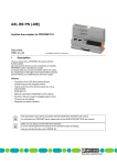
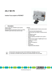
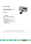
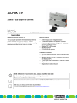
AXL BK S3 (-ME)
Axioline bus coupler for sercos
Data sheet
8200_en_01
1
© PHOENIX CONTACT 2012-05-03
Description
The bus coupler is intended for use within a third-generation Features of Axioline
sercos network and represents the link to the Axioline system.
– Connection of up to 63 other Axioline devices
Up to 63 Axioline devices can be connected to an existing
– Typical cycle time of the Axioline system bus: 10 s, apsercos network with the help of the bus coupler.
proximately
–
Runtime
in the bus coupler is negligible (goes to 0 µs)
Features
– Firmware can be updated
Features of sercos
– Diagnostic and status indicators
–
–
–
–
–
–
–
2 Ethernet-Ports
Transmission speed of 100 Mbps with a minimum sercos
cycle time of 31.25 µs
sercos diagnostic LED
Supports sercos V1.3
FSP-IO (Function Specific Profile-IO) for modular I/O devices
2 connections
Synchronization
This data sheet is only valid in association with the UM EN AXL SYS INST user manual.
You can find further information on sercos in the UM DE SERCOS SYS user manual.
Make sure you always use the latest documentation.
It can be downloaded from the product at www.phoenixcontact.net/catalog.
You will always find the current SDDML-files here.
AXL BK S3 (-ME)
2
Table of contents
1
Description .............................................................................................................................. 1
2
Table of contents ..................................................................................................................... 2
3
Ordering data .......................................................................................................................... 3
4
Technical data ......................................................................................................................... 4
5
Internal circuit diagram ............................................................................................................ 6
6
Connection of sercos and supply............................................................................................. 6
6.1
Connect sercos ................................................................................................................... 6
6.2
Connecting the supply voltage - terminal point assignment............................................................. 6
7
Connection example................................................................................................................ 7
8
Local status and diagnostic indicators ..................................................................................... 8
9
Mapping of I/O modules in sercos ........................................................................................... 9
10
sercos.................................................................................................................................... 10
10.1 sercos profile, classes and function groups .............................................................................. 10
10.2 Diagnostics: bus and user errors ........................................................................................... 11
10.3 Diagnose: periphery and channel error .................................................................................... 12
10.4 sercos address ................................................................................................................. 12
10.5 Password (IDN/S-0-0267) .................................................................................................... 12
11
sercos parameter................................................................................................................... 13
11.1 Overview of sercos parameters ............................................................................................. 13
12
Access to PDI objects............................................................................................................ 16
12.1 Mapping method ............................................................................................................... 16
12.2 Tunnel method .................................................................................................................. 16
13
Reset button .......................................................................................................................... 17
13.1 Restarting the bus coupler ................................................................................................... 17
13.2 Restoring the default settings................................................................................................ 17
14
Startup................................................................................................................................... 17
14.1 Starting the firmware .......................................................................................................... 17
14.2 Basic configuration............................................................................................................. 17
15
Firmware update.................................................................................................................... 18
8200_en_01
PHOENIX CONTACT
2
AXL BK S3 (-ME)
3
Ordering data
Description
Order No.
Pcs. / Pkt.
Axioline bus coupler for sercos (including bus base module and connector) AXL BK S3
2688116
1
Axioline bus coupler for sercos (electronics module as a replacement for
item 2688116 AXL BK S3)
AXL BK S3-ME
2688226
1
Accessories
Type
Order No.
Pcs. / Pkt.
Power plug for Axioline bus couplers (AXL BK ...)
AXL CN L/UL
2700979
1
Zack marker strip for Axioline (device labeling), in 2 x 20.3 mm pitch, unprinted, 25-section, for individual labeling with B-STIFT 0.8, X-PEN, or
CMS-P1-PLOTTER (Marking)
ZB 20,3 AXL UNPRINTED
0829579
25
Zack Marker strip, flat, Strip, white, Unlabeled, Can be labeled with: Plotter, ZBF 10/5,8 AXL UNPRINTED
Mounting type: Snap into flat marker groove, For terminal block width:
10.15 mm, Lettering field: 4 of 10.15 x 5 mm and 1 of 5.8 x 5 mm (Marking)
0829580
50
RJ45 connector, shielded, with bend protection sleeve, 2 pieces, gray for
straight cables, for assembly on site. For connections that are not crossed,
it is recommended that you use the connector set with gray bend protection
sleeve. (Plug/Adapter)
FL PLUG RJ45 GR/2
2744856
1
RJ45 connector, shielded, with bend protection sleeve, 2 pieces, green for
crossed cables, for assembly on site. For connections that are crossed, it
is recommended that the connector set with green bend protection sleeves
is used. (Plug/Adapter)
FL PLUG RJ45 GN/2
2744571
1
CAT5-SF/UTP cable (J-02YS(ST)C HP 2 x 2 x 24 AWG), heavy-duty instal- FL CAT5 HEAVY
lation cable, 2 x 2 x 0.22 mm², solid conductor, shielded, outer sheath: 7.8
mm diameter, inner sheath: 5.75 mm ± 0.15 mm diameter (Cable/conductor)
2744814
1
CAT5-SF/UTP cable (J-LI02YS(ST)C H 2 x 2 x 26 AWG), light-duty, flexible installation cable 2 x 2 x 0.14 mm², stranded, shielded, outer sheath:
5.75 mm ± 0.15 mm diameter (Cable/conductor)
FL CAT5 FLEX
2744830
1
Crimping pliers, for assembling the RJ45 connectors FL PLUG RJ45..., for
assembly on site (Tools)
FL CRIMPTOOL
2744869
1
Programming adapter with USB interface, for programming with the IFSCONF, MACX-MCR-CONF and UPS-CONF software (Cable/conductor)
IFS-USB-PROG-ADAPTER
2811271
1
Software for starting up and parameterizing Axioline stations
STARTUP+
2700636
1
Documentation
Type
Order No.
Pcs. / Pkt.
User manual, English, Axioline: System and installation
UM EN AXL SYS INST
-
-
User manual, English, sercos system manual for I/O devices
UM EN SERCOS SYS
-
-
Application note, English,
access to PDI objects from the modules of an Axioline station via sercos
AH EN SERCOS - PDI
-
-
8200_en_01
Type
PHOENIX CONTACT
3
AXL BK S3 (-ME)
4
Technical data
Dimensions (nominal sizes in mm)
122,4
75
Width
123,6
40
40 mm
Height
124 mm
Depth
75 mm
Note on dimensions
The depth is valid when a TH 35-7.5 DIN rail is used (according to EN 60715).
General data
Color
gray
Weight
174 g
Ambient temperature (operation)
-25 °C ... 60 °C
Ambient temperature (storage/transport)
-40 °C ... 85 °C
Permissible humidity (operation)
5 % ... 95 % (according to DIN EN 61131-2)
Permissible humidity (storage/transport)
5 % ... 95 % (according to DIN EN 61131-2)
Air pressure (operation)
70 kPa ... 106 kPa (up to 3000 m above sea level)
Air pressure (storage/transport)
70 kPa ... 106 kPa (up to 3000 m above sea level)
Degree of protection
IP20
Protection class
III, IEC 61140, EN 61140, VDE 0140-1
Connection data
Connection method
Spring-cage connection with direct plug-in method
Conductor cross section solid / stranded
0.2 mm² ... 1.5 mm²
Conductor cross section [AWG]
24 ... 16
Interface sercos
Connection method
RJ45 female connector, auto negotiation
Number
2
Transmission speed
100 MBit/s (Full duplex)
Transmission physics
Ethernet in RJ45 twisted pair
Transmission length
max. 100 m
Interface Axio bus
Connection method
Connection for bus base module
Transmission speed
100 MBit/s
8200_en_01
PHOENIX CONTACT
4
AXL BK S3 (-ME)
Interface Service (USB adapter)
Connection method
IFS-USB-PROG-ADAPTER
Number
1
System limits of the bus coupler
Amount of process data
1485 Byte (for each data direction)
Number of supported devices
max. 63 (per station)
sercos
Device profile
FSP_IO
Equipment type
sercos slave
Update rate
31.25 µs
Supply of the bus coupler
Supply of communications power UL
24 V DC
Maximum permissible voltage range
19.2 V DC ... 30 V DC (including all tolerances, including ripple)
Current supply at Ubus
2A
NOTE: Electronics may be damaged when overloaded
Provide external fuses for the 24 V UL area. The power supply unit must be able to supply four times the nominal current of the external fuse
to ensure that it blows in the event of an error.
Error messages to the higher level control or computer system
None
Protective circuit
Surge protection, protection against polarity reversal of the supply voltage Yes
Mechanical tests
Vibration resistance in acc. with IEC 60068-2-6
5g
Shock test in acc. with IEC 60068-2-27
25 g, 11 ms period, half-sine shock pulse
Bump endurance test according to EN 60068-2-29
10 g
Conformance with EMC Directive 2004/108/EC
Noise immunity test in accordance with EN 61000-6-2
Electrostatic discharge (ESD) EN 61000-4-2/IEC 61000-4-2
Criterion B; 6 kV contact discharge, 8 kV air discharge
Electromagnetic fields EN 61000-4-3/IEC 61000-4-3
Criterion A; Field intensity: 10 V/m
Fast transients (burst) EN 61000-4-4/IEC 61000-4-4
Criterion B, 2 kV
Transient surge voltage (surge) EN 61000-4-5/IEC 61000-4-5
Criterion B; DC supply lines: ±0.5 kV/±0.5 kV (symmetrical/asymmetrical); fieldbus cable shield: ±1 kV
Conducted interference EN 61000-4-6/IEC 61000-4-6
Criterion A; Test voltage 10 V
Noise emission test according to EN 61000-6-3
Radio interference properties EN 55022
Class B
Approvals
For the latest approvals, please visit www.phoenixcontact.net/catalog.
8200_en_01
PHOENIX CONTACT
5
AXL BK S3 (-ME)
5
Internal circuit diagram
6
Connection of sercos and supply
6.1
Connect sercos
S
SD
Connect sercos to the bus coupler via an 8-pos. RJ45 plug.
M
The sercos connections are set to autocrossing (auto crossover).
RDY
RJ45
D
LINK 1
RJ45
Install sercos in accordance with the specifications in the current "Planning and Installation
Guide" (see www.sercos.com).
ACT 1
LINK 2
FE
ACT 1
Also observe the information in the "sercos
system manual for I/O devices" user manual.
Service
!C
Reset
UL
Axio bus
UBus
3.3 V
UBus
24 V
The bus coupler does not support ring recovery of the sercos
following error rectification.
If the sercos ring was interrupted by an error, proceed as follows to reconnect the ring:
• Rectify the error.
• Ensure that the bus coupler runs through communication
phases CP0 to CP4.
6.2
UL
24 V
Figure 1
Ring recovery
Connecting the supply voltage - terminal point
assignment
Internal wiring of the terminal points
a1
a1
a2
a2
b1
b1
b2
b2
Key:
FE
Service
Reset
Optional functional earth ground connection
Service interface
Reset button
RJ45 interface
RJ45
Microprocessor
µC
Power supply unit
XXX
XXX
LED
8200_en_01
Figure 2
Terminal point assignment
Termi- Color
Assignment
nal
point
Supply voltage input
a1, a2
Red
24 V DC Communications power
supply (internally bridged)
(UL)
b1, b2
Blue
GND
Reference potential of the
supply voltage (internally
bridged)
PHOENIX CONTACT
6
AXL BK S3 (-ME)
7
Connection example
SERCOS III
a1
24 V DC +
(UL)
a2
b1
b2
Figure 3
8200_en_01
Connection of the cables
PHOENIX CONTACT
7
AXL BK S3 (-ME)
8
Local status and diagnostic indicators
S
SD
M
RDY
D
UL
Figure 4
LNK1
ACT1
LNK2
ACT2
Local status and diagnostic indicators
Designation
S
Color
Meaning
Red/Orange/ sercos diagGreen
nostics
SD
Red/Orange/ Sub device
Green
M
Yellow
Maintenance
RDY
Green
Ready
8200_en_01
State
OFF
Orange ON
Flashing orange/green
Flashing orange/green
Description
NRT mode; no sercos communication
CP0
CP1:
250 ms green, 2750 ms orange
CP2:
250 ms green, 250 ms orange,
250 ms green, 2250 ms orange
Flashing orCP3:
ange/green
250 ms green, 250 ms orange,
250 ms green, 250 ms orange,
250 ms green, 1750 ms orange
Green ON
CP4
Green flashing Loop back activated
Flashing red/or- User error; see chapter on "Diagnostics: bus and user erange
rors"
Flashing red/
MST loss
green
Red ON
Communication error
Flashing orIdentification (bit 15 in device control); is used for adange (2 Hz)
dress assignment and configuration errors.
Flashing red
Watchdog error
(2 Hz)
Green ON
Sub device is on the parameterization level (PL)
Orange ON
Sub device is on the operation level (OL)
Red ON
Error in the sub device (C1D)
OFF
Sub device is not active.
OFF
There is no maintenance request of an Axioline device.
ON
There is at least one maintenance request of an Axioline
device (e.g., device temperature at permissible limit)
ON
Device ready to operate
OFF
Device not ready to operate
Flashing
Device booting (for firmware update with boot requests)
PHOENIX CONTACT
8
AXL BK S3 (-ME)
Designation
D
Color
Red/yellow/
green
LNK 1/2
Green
ACT 1/2
Yellow
9
Meaning
Diagnostics
State
Red ON
Yellow ON
Description
Bus error
READY: Device is ready to operate, no data is exchanged
Yellow flashing I/O error in ACTIVE
Green ON
RUN: Data exchange; status and data from the higherlevel system is transmitted
Green flashing ACTIVE: Configuration is active, data exchange with invalid process data
Green/yellow
I/O error in RUN
alternating
Link port 1/2
ON
Connection via Ethernet to a module via port 1/2 established
OFF
No connection established via port 1/2
Activity port 1/2 ON
Transmission or reception of Ethernet telegrams at port
1/2
OFF
No transmission or reception of Ethernet telegrams at
port 1/2
Mapping of I/O modules in sercos
The local bus devices are assigned to the I/O function groups
and structure instances according to the sercos I/O profile.
Function group
A structure instance (slot) can consist if an I/O function group S-0-1501
or several I/O function groups (devices with inputs or outputs). S-0-1502
S-0-1503
The first Axioline device occupies slot 1 (structure inS-0-1504
stance 1), the second occupies slot 2 (structure instance 2)
etc.
S-0-1505
When assigning the inputs and outputs to the container input S-0-1506
data (S-0-1500.0.9) or to the container output data (S-0S-0-1507
1500.0.5), the input and output process data is always
mapped in byte limits in the container according to the sercos S-0-1508
I/O profile.
S-0-1509
The following function groups are defined:
S-0-1512
S-0-1513
S-0-1514
S-0-1515
S-0-1516
Name
I/O function group unknown
I/O function group digital output
Digital input
I/O function group analog output
I/O function group analog input
I/O function group counter
I/O function group complex protocol
I/O function group sub bus master
I/O function group sub bus slave
I/O function group PLC module
I/O function group motor starter
I/O function group PWM (pulse
width modulation)
I/O function group positioning
I/O function group passive
The bus coupler supports IDNs S-0-1500.0.2
and S-0-1500.0.9 in a producer connection
and IDNs S-0-1500.0.1 and S-0-1500.0.5 for
a consumer connection as configurable data.
This information is stored in IDNs S-0-0187 and
S-0-0188.
8200_en_01
PHOENIX CONTACT
9
AXL BK S3 (-ME)
10
sercos
10.1
sercos profile, classes and function groups
The following sercos profile, classes and function groups are
implemented in the module:
sercos device model
(GDP: Generic Device Profile)
- Basis device model (GDP_Basic)
- Diagnostics (FG_Diagnosis)
- Administration (FG_Administration
- Device identification (FG_Identification)
- Identification (GDP_Id)
- Function/Hardware/Firmware/Firmware loader version
(GDP_Rev)
- Password (GDP_PWD)
sercos communication model
(SCP: sercos Communication Profiles)
- Variable configuration (SCP_VarCfg)
- Identification of SCP classes (FG SCP Identification)
- Control of communication phases (FG Control)
- Telegram structure (FG Telegram Setup)
- Parameters for producer-consumer connection (FG
Connection)
- Bus diagnostics (FG Bus-Diagnostics)
- Parameters for the non-realtime channel (FG NRT)
- Timing behavior of the communication (FG Timing)
- Synchronous and isochronous producer and consumer
data (SCP_Sync)
- Diagnostics (SCP_Diag)
- Control of communication phases (FG Control)
- Bus diagnostics (FG Bus-Diagnostics)
- Non-realtime channel (SCP_NRT)
- Parameters for the non-realtime channel (FG NRT)
- Consumer connection monitoring; Watchdog (SCP_WD)
- Parameters for the producer-consumer connection
(FG Connection)
- Support for SCP_SIP and SCP_TFTP
- Cyclic communication (SCP_Cyc)
sercos function model
(FSP: Function Specific Profile I/O)
- I/O function profile (FSP_IO)
8200_en_01
PHOENIX CONTACT
10
AXL BK S3 (-ME)
10.2
Diagnostics: bus and user errors
sercos diagnostic
code (IDN S-00390.0.0) [hex]
Local bus error
C10F.B001
C10F.B002
C10E.B012
Message
Meaning
Remedy
Local bus device is
missing
Incorrect local bus device present
Device not
present
Wrong device
Local bus device peripheral or application
error
Error in a
local bus device
Install the device or check the contacts and replace a defective module, if necessary.
A wrong device was detected at the specified position.
Check the contacts, replace a defective module, if necessary
or adapt the configuration.
See corresponding data sheet.
Device error
C10F.B012
Application not ready
Application
on device not
ready
C10F.B013
Local bus device
power on reset
Local bus devices causes
a restart
Transmission error
C109.B022
Communication error
Multiple
transmission
error
C10F.B023
Data communication
error
I/O communication error
C10F.B024
Management communication error
Strong interference in
local bus
communication
Configuration errors
C10F.B030
Configuration error
General errors
C10F.B042
Firmware error
C10F.B041
Hardware error
8200_en_01
Read out via IDN 1500.0.32 to ascertain which device
and possibly which channel is affected and check the
contact, parameterization and function.
Check the specified channel of the device, the devices connected to the module, the parameters of the specified device
as well as the connected sensors and actuators.
Delay the start after power on or replace the device.
See corresponding data sheet.
The specified device executed a reset due to a fault or insufficient voltage supply. Check the power supply.
Find the cause by checking the power supply to the devices
and check whether they conform to the nominal value of the
permissible AC component.
Check the power supply unit of the bus coupler for overload
(see corresponding data sheet).
Check the system and replace devices, if necessary.
Bus errors occurred. The system has transmission errors.
Check the segment, shielding of the bus cables, grounding/
equipotential bonding, plugs, communications power (for
power drops), FO assembly, as well as the remote bus devices and whether the devices are aligned correctly.
Check the system, shielding of the bus cables, connectors,
grounding/equipotential bonding, voltage supply of the periphery and the voltage supply of the inputs/outputs.
Replace devices if necessary.
Check the system, shielding of the bus cables, connectors,
grounding/equipotential bonding, voltage supply of the periphery and the voltage supply of the inputs/outputs.
Replace devices if necessary.
configuration errors
The configuration is invalid. Replace device or modify configuration.
Firmware
error
Hardware
fault
Replace the device.
Replace the device.
PHOENIX CONTACT
11
AXL BK S3 (-ME)
10.3
Diagnose: periphery and channel error
Periphery and channel error can only occur once for each I/O
module or channel.
In accordance with the sercos specification, errors and messages are mapped in diagnostic IDNs S-0-0390, S-0-0095, S1500.0.32, and S-1500.0.33.
The messages are also entered in IDNs S-0-1303.0.10, S-01303.0.11, and S-0-1303.0.12.
You can also read out module-specific diagnostics via IDN P1-0024.x.0.
10.4
sercos address
There is no switch for setting the sercos address.
Default address 1 is used for manual address assignment.
The bus coupler supports remote address assignment of the
sercos address according to the sercos specification.
The sercos address is saved retentively.
For an automatic address assignment description, please refer to the documentation of your
sercos master.
10.5
Password (IDN/S-0-0267)
In the default setting some module parameters are write-protected with a password.
The default password is PW170875.
The following IDNs are password protected:
IDN
S-0-1020
S-0-1021
S-0-1022
P-0-2000.0.1
8200_en_01
Description
IP address
Subnet mask
Gateway address
Update procedure command
PHOENIX CONTACT
12
AXL BK S3 (-ME)
11
sercos parameter
11.1
Overview of sercos parameters
The following table lists all sercos parameters (S parameters)
with important features that have been implemented into the
bus coupler.
IDN
Name
Default values
Unit
S-0-0014
Interface status
-
-
S-0-0017
IDN list of all operation data
-
-
S-0-0021
IDN list of invalid operation data for CP2
-
-
S-0-0022
IDN list of invalid operation data for CP3
-
-
S-0-0025
IDN list of all procedure commands
-
-
S-0-0095
Diagnostic message
-
-
S-0-0099
Reset class 1 diagnostic (process command)
-
-
S-0-0127
CP3 transition check (process command)
-
-
S-0-0128
CP4 transition check (process command)
-
-
S-0-0187
IDN list of configurable data as producer
S-0-1500.0.2,
S-0-1500.0.9
ID
S-0-0188
IDN list of configurable data as consumer
S-0-1500.0.1,
S-0-1500.0.5
ID
S-0-0267
Password
PW170875
-
S-0-0279
IDN-list of password protected data
-
-
S-0-0390
Diagnostic number
-
-
S-0-1000
SCP type & version
-
S-0-1002
Communication cycle time (tScyc)
-
S-0-1003
Allowed MST losses in CP3/CP4
10
s
-
S-0-1005
Minimum feedback processing time (t5)
250 000
s
S-0-1006
AT0 transmission starting time (t1)
-
s
S-0-1007
Feedback acquisition capture point (t4)
-
s
S-0-1008
Command value valid time (t3)
-
S-0-1009
Device control (C-Dev) offset in MDT
-
-
s
S-0-1010
Length of MDTs
-
S-0-1011
Device status (S-Dev) offset in AT
-
-
S-0-1012
Length of ATs
-
-
S-0-1013
SVC offset in MDT
-
-
S-0-1014
SVC offset in AT
-
-
S-0-1015
Ring delay
-
s
S-0-1016
Slave delay
-
s
S-0-1017
NRT transmission time
650 000
950 000
s
S-0-1019
MAC address
00.A0.45.xx.xx.xx
S-0-1020
IP address
192.168.0.10
-
S-0-1021
Subnet mask
255.255.255.0
-
S-0-1022
Gateway address
192.168.0.1
-
S-0-1023
SYNC jitter
1000
S-0-1024
SYNC delay measuring procedure command (Prozesskommando)
-
-
s
S-0-1026
Version of communication hardware
-
-
S-0-1027.0.1
Requested MTU
-
-
S-0-1027.0.2
Effective MTU
-
-
S-0-1028
Error counter MST-P/S
-
-
S-0-1031
Test pin assignment Port 1 and Port 2
-
-
8200_en_01
PHOENIX CONTACT
13
AXL BK S3 (-ME)
IDN
Name
Default values
Unit
S-0-1035
Error counter Port1 and Port2
-
-
S-0-1040
SERCOS address
1
-
S-0-1041
AT Command value valid time (t9)
-
S-0-1044
Device control
-
-
S-0-1045
Device status
-
-
S-0-1047
Maximum consumer activation time (t11)
-
S-0-1050.x.1
Connection setup
-
s
s
-
S-0-1050.x.2
Connection number
-
-
S-0-1050.x.3
Telegram assignment
-
-
S-0-1050.x.4
Max. length of connection
-
-
S-0-1050.x.5
Current length of connection
-
-
S-0-1050.x.6
Configuration list
-
-
S-0-1050.x.8
Connection control
-
-
S-0-1050.x.10
Producer cycle time
-
S-0-1050.x.11
Allowed data losses
-
s
S-0-1050.x.12
Error counter data losses
-
-
S-0-1050.x.20
IDN allocation of real-time bit
-
-
-
S-0-1050.x.21
Bit allocation of real-time bit
-
-
S-0-1051
Image of connection setups
-
-
S-0-1300.x.1
Component name
xxxx...
S-0-1300.0.2
Vendor name
Phoenix Contact
-
S-0-1300.0.3
Vendor code
200
-
S-0-1300.0.4
Device name
xxxx...
-
S-0-1300.0.5
Device ID
xxxxxxx
-
S-0-1300.0.6
Connected to subdevice
-
-
S-0-1300.0.7
Function revision
-
-
S-0-1300.0.8
Hardware revision
-
-
S-0-1300.0.9
Software revision
-
-
S-0-1300.0.10
Firmware loader revision
-
-
S-0-1300.0.11
Order number
xxxxxxx
S-0-1300.0.12
Serial number
xxx
-
S-0-1300.0.13
Manufactoring date parameter
-
-
S-0-1300.0.20
Operational hours
-
h
S-0-1301
List of GDP classes & version
0101hex
-
S-0-1302.0.1
FSP type & version
00010001hex
-
S-0-1302.0.2
Function groups
S-0-1500.0.0
-
S-0-1302.0.3
Application type
Modular IO station
-
S-0-1303.0.01
Diagnosis trace configuration
-
-
S-0-1303.0.02
Diagnosis trace control
-
-
S-0-1303.0.03
Diagnosis trace state
-
S-0-1303.0.10
Diagnosis trace buffer no1
-
-
S-0-1303.0.11
Diagnosis trace buffer no2
-
-
S-0-1303.0.12
Diagnosis trace buffer no3
-
-
S-0-1305.0.1
sercos current time
-
-
S-0-1500
I/O bus coupler
-
-
S-0-1500.x.1
IO control
-
-
S-0-1500.x.2
IO status
-
-
S-0-1500.x.3
List of module type codes
-
-
S-0-1500.x.5
Container output data
-
-
S-0-1500.x.9
Container input data
-
-
8200_en_01
PHOENIX CONTACT
14
AXL BK S3 (-ME)
IDN
Name
Default values
S-0-1500.x.19
Parameter channel receive
-
Unit
-
S-0-1500.x.20
Parameter channel transmit
-
-
S-0-1500.x.23
Local bus cycle time
-
S-0-1500.x.32
IO diagnostic message
-
-
S-0-1500.x.33
Current IO diagnostic message
-
-
S-0-1501
I/O function group unknown
-
-
S-0-1502
I/O function group digital output
-
-
s
S-0-1503
I/O function group digital input
-
-
S-0-1504
I/O function group analog output
-
-
S-0-1505
I/O function group analog input
-
-
S-0-1506
I/O function group counter
-
-
S-0-1507
I/O function group complex protocol
-
-
S-0-1508
I/O function group sub bus master
-
-
S-0-1509
I/O function group sub bus slave
-
-
S-0-1512
I/O function group PLC module
-
-
S-0-1513
I/O function group motor starter
-
-
S-0-1514
I/O function group PWM (pulse width modulation)
-
-
S-0-1515
I/O function group positioning
-
-
S-0-1516
I/O function group passive
-
-
P-1-x.y.z
sercos SVC/PDI 1:1 mapping (x = PDI-Index, y = module slot, z = Subindex)
-
-
P-0-2000.0.1
Update command (process command)
-
-
You can find further information on sercos parameters in the UM DE SERCOS SYS user
manual.
8200_en_01
PHOENIX CONTACT
15
AXL BK S3 (-ME)
12
Access to PDI objects
12.2
Tunnel method
You can use the tunnel method for all PDI objects.
You can access PDI objects from the modules of a station via
You tunnel the PDI object through the function groups of the
sercos. You have two options here:
FSP_I/O, i.e. through IDNs S-0-1501 to S-0-1516.
- Mapping method
S-0-15xx.y.19
Parameter channel receive
- Simple method
Receiving
the response via the service
- For PDI objects with the index 0001hex ... 1000hex
channel
- Tunnel method
S-0-15xx.y.20
Parameter channel transmit
- More complex method
Transferring data to the parameter
- For all PDI objects
channel via the service channel
y
Module slot
Detailed information on accessing PDI objects
1st module after the bus coupler = 1
from the modules of an Axioline station via ser:
cos can be found in the AH DE SERCOS - PDI
application note.
63rd module after the bus coupler = 63
12.1
Mapping method
You can use the mapping method for PDI objects with the
index 0001hex ... 1000hex (1dec ... 4096dec).
To do so, map the PDI object in the manufacturer-specific parameter P-1-x.y.z
P-1-x.y.z
x
y
z
Example:
8200_en_01
sercos SVC/PDI 1:1 mapping
PDI index (decimal)
maximum: P-1-4096.y.z
Module slot
Bus coupler = 0
1st module after the bus coupler = 1
:
63rd module after the bus coupler = 63
Subindex
P-1-0010.15.0
PHOENIX CONTACT
16
AXL BK S3 (-ME)
13
Reset button
14
Startup
The reset button is on the front of the bus coupler.
14.1
Starting the firmware
The reset button has two functions:
– Restarting the bus coupler
– Restoring the default settings
The firmware is started after you have supplied power to the
bus coupler.
13.1
The bus coupler is ready for operation when the RDY LED
lights up permanently green.
Restarting the bus coupler
The bus coupler is restarted when the button is pressed dur- 14.2 Basic configuration
ing operation.
The bus coupler executes the basic communication after
The outputs of the station are set to the parameterized substi- switching on the bus coupler or after resetting with the reset
tute values.
button and the first entry into the CP2 communication phase.
The process image of the inputs is not re-read.
These means:
–
13.2
Restoring the default settings
The bus coupler is supplied with the following default settings:
–
Default values (default settings)
S-0-1019
00-A0-45-xx-xx-xx
S-0-1020
192.168.0.10
S-0-1021
255.255.255.0
S-0-1022
192.168.0.1
S-0-1040
1
S-0-0267
PW170875
S-0-1302.0.3
Modular IO station
MAC address
IP address
Subnet mask
Gateway address
sercos address
Password
Application type
Holding down the button during the initialization phase restores the default settings.
If you wish to restore the default settings, proceed as follows:
• Disconnect the power to the module.
• Press and hold down the button.
• Switch on the power.
–
–
The corresponding I/O function groups and the structure
elements are generated for all devices detected on the local bus.
Channel number and width correspond to the detected
data widths of the devices.
The input/ output process data of all I/O function groups
are configured via IO_FG.x.2 for mapping in S-01500.0.5 (container output data) or S-0-1500.0.9 (container input data).
The content an lengths of the input/output process data is
mapped 1:1 to sercos.
By switching over the communication phases to CP3 and subsequently in CP4, the sercos master now has the possibility,
to accept this configuration for real-time operation without
change or to make changes and to activate them before
switching to CP3.
The LEDs indicate the initialization phase:
LED
RDY
RDY
RDY
•
State
OFF
Flashing
Green
Meaning
Starting firmware
Initializing firmware
Initialization complete
When the RDY LED lights up green, release the button.
The default settings are restored.
8200_en_01
PHOENIX CONTACT
17
AXL BK S3 (-ME)
15
Firmware update
Firmware update
After the bus coupler restart, the firmware update is perThe firmware update is carried out in accordance with the proformed automatically.
cedure described in the sercos specification. This means that
a TFTP server is implemented on the bus coupler, which can
The firmware update can take several minutes.
receive files from any TFTP client. The file for the update is
saved by the bus coupler in the file system, verified, and, if
Never disconnect the supply voltage during the
found to be valid, transferred to the program code area of the
firmware update process.
memory during the boot phase following a reset (power
down). This process can take a few minutes.
The firmware update is automatically completed with a bus
coupler restart.
Update requirements
The status LEDs signal the current status of the firmware up– In the following, the term "PC" will be used as a general date.
term for a PC and notebook, or similar.
LED states: firmware update is being performed
– To make sure that no settings are lost during updating,
take suitable measures to back up the device settings.
Meaning
– In order to establish a connection to the Axioline bus cou- LED
pler, it may be necessary to deactivate the firewall of your RDY flash- BootP requests are sent and the firmware coning
tainer is loaded via tftp.
PC.
RDY ON / Firmware is saved.
– Current firmware update file is available from the download area of the bus coupler at www.phoenixcontact.net/ M ON
catalog.
Transfer file for firmware update to the bus coupler (us- LED states: update complete
ing Windows XP)
LED
Bus coupler without
• Save the current firmware update file to your PC.
connected modules
• Rename the file c2688226.fw.
S3
OFF
• Connect the bus coupler to the the LAN card of your PC SD
Orange
via an Ethernet cable.
M
OFF
• Switch on the power supply to the bus coupler.
RDY
Green
• Make sure that the IP address of your PC is in the same
D
Orange
ip address space as the bus coupler, which you wish to
update.
• Run the command console of your PC.
• Enter the following command line: tftp -i <ip-address of
the bus coupler> PUT <name of the update file>
Bus coupler with
connected modules
OFF
Orange
OFF
Green
Green flashing
tftp -i <ip address> PUT <file name>
ip address IP address of the bus coupler
file name
Name of the update file
Example:
tftp -i 192.168.0.2 PUT c2688226.fw
tftp -i 192.168.0.2 PUT c2688226.fw
•
Once the firmware file has been successfully transferred,
restart the bus coupler by resetting the voltage or execute
IDN/P-0-2000.0.1.
8200_en_01
PHOENIX CONTACT GmbH & Co. KG • 32823 Blomberg • Germany
www.phoenixcontact.com
18