1
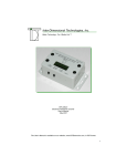
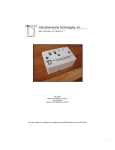
Getting Started
with the
RTC-P3 Pedestrian Counter
and
Transmission & Graphical Traffic-Analysis Software
Better Technology...For A Better Life
Inter-Dimensional Technologies, Inc.
July 2004
Firmware Version 5.1
-1-
1. Install the Hardware
a. Run the Communications Cable(s)
b. Install the RTC-P3 Traffic Counter
i. Connect the RTC-P3 to the PC (optional)
ii. Connect the RTC-P3 to the Door Sensor(s)
iii. Connect the RTC-P3 to the Wall Outlet
c. Install the Door Sensors
i. Install the RTC-S2X Standard Door Sensor (optional)
1. Mount the RTC-S2X Enclosure
2. Find the “Sweet Spot” of the Infrared Beams
3. Mount the Reflector
ii. Install the RTC-S2XL Long-Range Door Sensor (optional)
1. Run the Communications Cable Over the Top of The Entrance
2. Mount one of the Enclosures for the RTC-S2XL
3. Find the “Sweet Spot” of the Infrared Beams
4. Mount the other Enclosure for the RTC-S2XL
d. Continue Setting Up the RTC-P3
2. Test the Hardware
3. Install the Software (optional)
a. Insert Installation CD
b. Begin Software Installation
c. Select Directory for Programs
4. Set up the Software
a. Set up a Shortcut Icon to the Software
b. Select Transmission Option
c. Select Data Directory
Better Technology...For A Better Life
Inter-Dimensional Technologies, Inc.
Installation Overview
-2-
Introduction
The RTC-P3 User’s Manual is approximately 47 pages and the Transmission & Graphical
Traffic-Analysis software User’s Manual is approximately 35 pages. There are sections in
these manuals that give a detailed explanation as to how to install the hardware and software, while also explaining the technology that is used and the options that can be used.
However, this may be too much information for some individuals.
The following overview should be completed in the order shown. Also, you can refer to the
RTC-P3 User’s Manual for typical installation diagrams or more detailed information when
needed.
1. Install the Hardware
a. Run the Communications Cable(s)
The first step in the installation process should be to install the communications cable that connects the RTC-P3 traffic counter to each door sensor.
This is Category 5 cable, which is a very common cable that is used to connect many computer networks.
If there is a long distance from the traffic counter to the door sensor(s), or if
the cable needs to be run in the ceiling or walls, it may be advantageous to
hire a third party to run the cable, such as a network installer, licensed electrician or contractor.
Better Technology...For A Better Life
Inter-Dimensional Technologies, Inc.
This document can be useful for all individuals, regardless of if the individual chooses to read
these other manuals or not. For individuals in the Information Technology field, or others
who feel comfortable with a brief overview of the system, this document may be enough to
complete the installation. For those who choose to read the User’s Manuals, this document
will still be a good place to start, as it will give basic information, without becoming too detailed.
If the cable is to be run inside walls or ceilings, the cable should have plenum shielding to help conform to fire codes. If it is to be run outside the wall
PVC shielding will be sufficient. The cable should be kept as far away from
florescent lighting, relays, motors, power cables and any other devices that
may radiate EMI. If the networking cable must cross a power cable, they
should be crossed at right angles. Do not run the communications cable and
power cable along side each other.
If the cable is going to be run outside the wall, be sure to tie the cable to the
base of the wall with the supplied cable ties.
b. Install the RTC-P3 Traffic Counter
Find a location for the RTC-P3 traffic counter to be placed. It should be
placed near the PC or POS to which it is being connected. We supply a Serial cable that is six feet in length. This is the cable that is used to connect
the traffic counter to the PC. Also, the Serial Communications standard dictates that the two devices cannot be more than 50 feet apart.
i. Connect the RTC-P3 to the PC (optional)
The RTC-P3 does not need to be connected to a PC in order to operate. The only time that the RTC-P3 and the PC interact is when
the traffic data is being transmitted. Therefore, if a PC is not available at the establishment, a laptop can be connected to the RTC-P3
periodically and the traffic data transmitted. In either case, the following should be done when connecting the RTC-P3 to the PC.
-3-
Find the Serial cable that was included with the RTC-P3. It is the
cable with the nine-pin connectors. Connect the cable into the port
on the RTC-P3 labeled, “RS-232.” Connect the other end of the cable into a Serial port on the PC. If the PC does not have an available Serial port, the RTC-P3 can be connected to a USB port with a
Serial-to-USB converter that we resell.
ii.Connect the RTC-P3 to the Door Sensor(s)
In Step 1.a, the communications cable was installed. Now, it’s time
to connect the ends of the cable. Connect one end of the cable to
one of the three door sensor ports, labeled “Door 1,” “Door 2” and
“Door 3.” It does not matter into which port the cable is plugged.
However, it is usually only natural to start at Door 1. This will also
make it more logical when analyzing the data with the software.
iii.
Connect the RTC-P3 to the Wall Outlet
Plug the two-prong connector on the power supply into the wall.
Plug the other end of the cable into the RTC-P3’s “Power” socket.
Do not turn on the traffic counter yet. We will turn it on after we have
the door sensors mounted.
Better Technology...For A Better Life
Inter-Dimensional Technologies, Inc.
For now, leave the other end of the cable unconnected. That will be
done when the door sensors are installed. If there is more than one
door sensor, connect the other cables to the RTC-P3 in the same
fashion.
c. Install the Door Sensors
Background:
The door sensors use infrared (invisible) beams to detect pedestrians passing through the entrance. Both, the RTC-S2X standard door sensor and
RTC-S2XL long-range door sensor use this technology. However, the RTCS2X is a box that is mounted on one side of the entrance and a reflector on
the other side. The RTC-S2XL has a box on each side of the entrance and
does not use a reflector.
The RTC-S2X and RTC-S2XL actually emit two infrared beams. Two beams
are used so that the system can determine whether a pedestrian is entering
or leaving. It can do this because, in the split second that a pedestrian
passes, the system can tell which beam was broken first. If the beam closer
to the exterior of the establishment is broken first, then the system knows
that the pedestrian entered the establishment. If the beam closer to the interior of the establishment is broken first, then the system knows that the pedestrian left the establishment.
The RTC-P3 can accept up to three of these door sensors, in any combination.
Sensor Mounting Height:
There are various schools of thought as to how high off the ground the door
sensors should be mounted. We recommend that they be mounted at approximately thigh-height. If the sensors are mounted too low (knee-height,
for example), the system could lose accuracy because of the angle in which
the lower leg crosses the beams. If the sensors are mounted too high (five
feet, for example), the system may not always count shorter pedestrians (5’
5”, for example).
There is one obscure, but important, point to mention concerning the mounting height of the door sensors. As described earlier in this section, the door
-4-
sensors can determine if a pedestrian is entering or leaving the establishment, based on which beam is broken by the pedestrian first. Many establishments have the very common single- or double-swinging glass doors.
These typically swing outside of the building and have a push bar for the
customer to use when opening the door when exiting with their hands full.
Be sure that you don’t mount the door sensors at the same height as the
push bar. That is because, as the pedestrian is leaving, he will raise his
hand to push the push bar. He may reach over the top of the beams and not
break them, but then, after he pushes the door open, his arm will swing
down, causing the beam closer to the exterior to be broken first. The system
will interpret this as a pedestrian entered the establishment. Therefore, do
not mount the sensor at (or approximately at) the height of the push bars.
i. Install the RTC-S2X Standard Door Sensor (optional)
1. Mount the RTC-S2X Enclosure
Mount the RTC-S2X enclosure on the wall or molding near
the entrance. The two red alignment LED’s and two round
sensors protruding from the side should be pointed such that
they point across the entrance area.
Use a level to ensure that the enclosure is mounted so that it
is level and parallel to the ground. See the installation diagram in the RTC-P3 User’s Manual.
2. Find the “Sweet Spot” of the Infrared Beams
NOTE: There are a number of diagrams in the RTC-P3
User’s Manual pertaining to the sweet spot.
Better Technology...For A Better Life
Inter-Dimensional Technologies, Inc.
Also, if the establishment has a door that physically swings into the building,
this may cause the system to not count properly. There is a menu option
that can fix this. See the “Door Count Type” option in the RTC-P3 User’s
Manual for more details.
The infrared beams that are emitted from the door sensors
actually spread out as they get further away from the door
sensor. This is to help with alignment of the RTC-S2X with
the reflector.
There is usually an area of approximately five inches in diameter when the beams reach the other side of the entrance
area. It is best to orient the reflector in the center of this
area. This is what we call the “sweet spot.” The reason this
should be done is to ensure that, if the reflector is bumped,
the door sensor will stay aligned with the reflector. However, if the reflector is oriented such that it is on the edge of
one of the infrared beam, it can be bumped out of alignment
rather easily.
Therefore, it is imperative to orient the reflector in the middle
of the sweet spot. The next thing to do is to turn the power
on to the RTC-P3. (The RTC-P3 will be prompting the user
for additional information; however, we will address these
prompts later.) Turning on the power to the RTC-P3 will
now supply power to the RTC-S2X door sensor via the communications cable, and therefore, turn on the red alignment
LED’s.
-5-
When an alignment LED is turned on, it means that the sensor immediately below that LED is not aligned with the reflector. Therefore, if both LED’s are turned on, then neither
sensor is aligned with the reflector.
Now, hold the reflector in your hand and move it up, down,
left and right, while observing when the red alignment LED’s
turn off and on. Continue to move the reflector until the
sweet spot is found. Again, the sweet spot will be the area
where the reflector can be moved without the alignment
LED’s turning on.
When a pedestrian passes through the beams, the red alignment LED’s will flash quickly. This is normal.
ii.Install the RTC-S2XL Long-Range Door Sensor (optional)
Better Technology...For A Better Life
Inter-Dimensional Technologies, Inc.
3. Mount the Reflector
Once the sweet spot is found, mount the reflector and
bracket on the wall at the correct vertical position. Also,
slide the reflector along the slot of the bracket to adjust the
horizontal position of the reflector. After the reflector is
mounted, the red alignment LED’s should turn off.
1. Install the Communications Cable Over the Top of The
Entrance
The RTC-S2XL has two boxes, the “master” (RTC-S2XLM)
and the “slave” (RTC-S2XLS). Although they are two separate enclosures, they act as one unit. Therefore, a communications cable must connect the two enclosures. Typically,
it is run up the entrance, across the top of the entrance and
then down the other side. It can usually be hidden away
fairly well by securing the cable along the molding of the entrance with the supplied cable ties. This cable can obviously
be mounted in the wall, if desired.
If this cable is longer than needed, it will look sloppy. Therefore, measure the amount of cable that will be needed.
First, it must be determined at what height the enclosures
will be mounted. The length of cable will be the distance
from the enclosure up to the top of the entrance, plus the
distance across the entrance, plus the distance back down
to the other enclosure.
It’s best to install this cable before attempting to mount and
align the RTC-S2XL enclosures.
2. Mount one of the Enclosures for the RTC-S2XL
Mount one of the enclosures for the RTC-S2XL on the wall
or molding near the entrance. The red alignment LED and
two round sensors protruding from the side should be
pointed such that they point across the entrance area.
Use a level to ensure that the enclosure is mounted so that it
is level and parallel to the ground.
Connect the cable that was run over the top of the entrance
to the enclosure. If the master enclosure is the one currently
-6-
being mounted, that cable should be put in the “RTCS2XLS” port. You can also connect the cable that was run
back to the RTC-P3 to the “RTC-P3” port. If the slave enclosure is the one currently being mounted, the cable that is run
over the top of the entrance should be put in the “RTCS2XLM” port.
There is usually an area of approximately five inches in diameter when the beams reach the other side of the entrance
area. It is best to orient each enclosure such that it is in the
center of this area of the other enclosure. This is what we
call the “sweet spot.” The reason this should be done is to
ensure that, if one of the enclosures is bumped, they will
keep their alignment. However, if one of the enclosures is
oriented such that it is on the edge of one of the infrared
beam, it can be bumped out of alignment rather easily.
Therefore, it is imperative to orient each enclosure in the
middle of the sweet spot. The next thing to do is to turn the
power on to the RTC-P3. (The RTC-P3 will be prompting
the user for additional information; however, we will address
these prompts later.) Turning on the power to the RTC-P3
will now supply power to the RTC-S2XL door sensor via the
communications cable, and therefore, turn on the red alignment LED’s.
Better Technology...For A Better Life
Inter-Dimensional Technologies, Inc.
3. Find the “Sweet Spot” of the Infrared Beams
The infrared beams that are emitted from the door sensors
actually spread out as they get further away from the door
sensor. This is to help with alignment of the infrared beams
that are emitted from the two RTC-S2XL’s enclosures.
When an alignment LED is turned on, it means that the
beam immediately below the LED is not aligned with the
other enclosure. Therefore, if both LED’s are turned on,
then both enclosures are not aligned.
Next, connect the cable that was run over the top of the entrance to the enclosure. If the master enclosure is the one
currently being mounted, that cable should be put in the
“RTC-S2XLS” port. You can also connect the cable that
was run back to the RTC-P3 to the “RTC-P3” port. If the
slave enclosure is the one currently being mounted, the cable that is run over the top of the entrance should be put in
the “RTC-S2XLM” port.
Now, hold the enclosure that is not mounted yet, in your
hand and move it up, down, left and right, while observing
when the red alignment LED’s turn off and on. Continue to
move this enclosure until the sweet spot is found. Again, the
sweet spot will be the area where the unmounted enclosure
can be moved without the alignment LED’s turning on.
4. Mount the other Enclosure for the RTC-S2XL
Once the sweet spot is found, mount the unmounted enclosure on the wall at the correct vertical position. Also, slide
the enclosures along the slots of the brackets to adjust the
horizontal position. After both enclosures are mounted, the
-7-
red alignment LED’s should turn off.
When a pedestrian passes through the beams, the red alignment LED’s will flash quickly. This is normal.
5. Continue Setting Up the RTC-P3
Earlier in this document, it was stated that the RTC-P3 will
prompt the user for more information when it was turned on.
Now, we will answer these prompts. First, the display contrast should be adjusted so that the text can be viewed easily. See the “Adjust Contrast” option in the Menu Options
section of the RTC-P3 User’s Manual.
At this point in time, the installation of the hardware is complete. However, although the door sensors’ infrared beams
are aligned correctly, there should still be some basic testing
of the door sensor installations. That will be discussed next.
2. Test the Hardware
In the case of the RTC-S2X standard door sensor, if the beams hit the reflector at a
right angle, they should reflect back to the RTC-S2X perfectly. In the case of the
RTCS2XL long-range door sensor, if the beams from the enclosures hit the other at
right angles, they are optimally aligned.
Better Technology...For A Better Life
Inter-Dimensional Technologies, Inc.
Next, the date, day-of-week and time must be set. See the
“Set Date/Time” option in the Menu Options section of the
RTC-P3 User’s Manual. Please note that the time is in 24hour military format.
However, if the beams are not at right angles, subtle problems can arise. In the case
of the RTC-S2X, if the beams do not hit the reflector at a right angle, they will not reflect back to the RTC-S2X perfectly. Then why don’t the red alignment LED’s become lit? If the reflector is not perpendicular to the beams, both beams will reflect
back to one side of the RTC-S2X slightly. One of the beams may reflect back to both
sensors in the door sensor enclosure. When this beam is broken, both sensors will
blink simultaneously, or near simultaneously. This will cause the system to interpret
every pedestrian as always entering or always leaving, depending upon which side
of the RTC-S2X the beams are being reflect back to.
Therefore, we should test to make sure our beams are aligned at right angles. First,
you should understand what the beeps mean when a pedestrian passes through an
entrance. The beep that is heard when a pedestrian enters should be longer than
the beep that is heard when a pedestrian leaves. Therefore, the best way to check
the door sensors is to sweep your arm through the path of the beams, as though you
are simulating a pedestrian entering the establishment. Observe the length of the
beep. Next, sweep your hand through the path of the beams, as though you are
simulating a pedestrian leaving the establishment. Once again, observe the beep. It
should be a shorter beep than when simulating the pedestrian entering. This test
should be done a few inches from the door sensor, then in the middle of the entrance, and finally, a few inches away from the reflector. This is because you may
get varying results in different areas of the entrance, especially if the entrance is
more than a few feet wide. Please note, that you may get a few erroneous hits near
the reflector. This can be caused by the reflection of the beams off of the reflector. If
these erroneous hits seem to be affecting the traffic drastically, the reflector can be
moved further away from the RTC-S2X.
3. Install the Software (optional)
The software that we supply with the RTC-P3 performs two functions. It communi-8-
cates with the RTC-P3 and also allows the user to view and print the traffic data.
Our software does not need to be used with the RTC-P3; however, we recommend
that you use it. Our software does not need to be used because we use industry
standards. First, the RTC-P3 communicates via standard Serial communications.
This means that virtually any communications application can be used. Second, the
data is transmitted in a standard comma-delimited format. Virtually any software application can import a comma-delimited ASCII format, such as Microsoft Excel, or a
custom database application.
a. Insert Installation CD
Insert the installation CD into the CD drive.
c. Select Directory for Programs
A window will appear where the user will select the drive and directory where
the software will be installed. We recommend that the software be installed
in c:\idt; however, it can be placed anywhere the user desires, including network drives.
IMPORTANT NOTE: The installation program will not support any
subdirectories that contain spaces in the name, for example,
“Program Files.”
There are four buttons in the window.
The <Cancel> button will cancel the entire installation, the program will end
and there will be no programs written to the drive.
Better Technology...For A Better Life
Inter-Dimensional Technologies, Inc.
b. Begin Software Installation
Click “Start” and then click “Run.” A window will appear. Enter the CD drive
letter followed by \install. For example, if the CD drive is e:, then the user
would enter, e:\install. The user can also click the <Browse> button to select
the file. After the file name is set, click the <OK> button. The installation
process will begin.
The <Install> button will copy the files to the selected directory and the installation process will be completed within a few seconds. If the installation is
successful, a window will appear stating, “Installation Complete.”
The <Prev Dir> button will take the user backwards one directory.
The <Make Dir> button will allow the user to create a subdirectory in the currently-selected directory. A window will appear where the user can enter the
name of the subdirectory.
Once the directory is selected, click the <Install> button and the programs
will be copied. The software is now installed.
4. Set up the Software
Although the software was installed in the previous step, a program group or shortcut
to the program is not created. Therefore, it is recommended that a shortcut be created and placed on the desktop. Otherwise, the main program would have to be
found using Windows Explore, which allows the user to traverse through the hard
drive and its files and directories.
Below is a short summary of the various options that can be used when creating the
various shortcuts. If you are not familiar with how to create a shortcut, please refer
to the RTC-P3 Graphing/Transmission Software User’s Manual. The manual gives
step-by-step instructions with sample windows to help guide you through the proc-9-
ess.
b. Select Transmission Option (optional)
Although the user will have access to all of the software options, there m ay
be times where the manager or owner may not want the employees to have
access to all of the options. Many times, the employee on duty will transmit
the data, but the manager or owner will display and print the traffic data. In
this case, a shortcut can be created that, when double-clicked, will initiate
the transmit process directly, rather than having to select it from the main
menu. A window will open and display the traffic data that is being transmitted, and then it will close. Therefore, the user only has to double-click the
icon and the transmit process will take place and be completed in a few seconds.
To create this shortcut icon, create the same shortcut icon that was described in Step 7.a. However, we will add some text at the end of the target
field. As stated above, the target is field is c:\idt\trx.exe; however, in order to
bypass the main menu and start the transmit process directly, add the text, autotransmit to the field. Therefore, the target field will be c:\idt\trx.exe –
autotransmit. Be sure that there is a space before the hyphen a nd that there
is no space after the hyphen.
Better Technology...For A Better Life
Inter-Dimensional Technologies, Inc.
a. Set up a Shortcut Icon to the Software (optional)
Create a shortcut to the trx.exe file that is in the directory in which the software was installed. Let’s assume, for these examples, that the installation
directory is c:\idt. The target field in the shortcut properties will be c:\idt\trx.
exe. Double-clicking on this shortcut icon will start the software and display
the main menu. This menu gives the user access to all of the options, which
include the Transmit option, the Graph option and the software settings.
c. Select Data Directory (optional)
By default, the traffic data files will be placed in c:\idt. However, there is a
way to set an alternative data directory. The data in this directory will be
read when displaying and printing. The program will also write the data to
this directory when receiving data from the RTC-P3 when transmitting.
First, create a shortcut as described in Step7.a. The target field is c:\idt\trx.
exe. However, in order to read and write the data to a different directory,
add the text, -datadir=x:\newdir, where x: is the drive letter and newdir is the
directory name. So, an example of the target field is c:\idt\trx.exe –datadir=c:
\idt\data.
This is particularly useful when data is received from various locations and
analyzed on a single PC, such as at a corporate office. There should be a
shortcut icon created for each location, but with a unique data directory for
each. Then, when one of the shortcut icons is selected, the main menu will
appear and the data that is displayed or printed will be from the directory that
is specified in the target field of that shortcut.
See the software’s user’s manual for further information.
- 10 -
Contact Information
Mailing Address: Inter-Dimensional Technologies, Inc.
P.O. Box 392
Hop Bottom, PA 18824-0392
Shipping Address: Inter-Dimensional Technologies, Inc.
322 Greenwood Street
Hop Bottom, PA 18824
Voice/Fax: 570.289.0989
Better Technology...For A Better Life
Inter-Dimensional Technologies, Inc.
E-Mail Address: [email protected]
Website Address: www.IDTElectronics.com
- 11 -