1
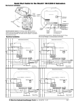
Shark® 100S/200S Quickstart
Shark® 100S/200S Meter Quickstart Guide
WARNING! During normal operation of the meter
dangerous voltages flow through many parts of the meter,
including Terminals and any connected CTs and PTs, all I/O
modules and their circuits. All Primary and Secondary
circuits can, at times, produce lethal voltages and currents. Avoid
contact with any current-carrying surfaces. Before performing ANY
work on the Shark® 100S/200S meter, make sure the meter is
powered down and ALL circuits are de-energized.
AVERTISSEMENT! Pendant le fonctionnement normal du compteur
Shark® 100S/200S des tensions dangereuses suivant de nombreuses
pièces, notamment, les bornes et tous les transformateurs de courant
branchés, les transformateurs de tension, toutes les sorties, les entrées
et leurs circuits. Tous les circuits secondaires et primaires peuvent
parfois produire des tensions de létal et des courants. Évitez le contact
avec les surfaces sous tensions. Avant de faire un travail dans le
compteur, assurez-vous d'éteindre l'alimentation et de mettre
tous les circuits branchés hors tension.
Front Cover
Support fitted
into its base
IMPORTANT! All wiring is done with the cover open, as shown above. The front cover support fits into its base.
Make sure the support is up before closing the front cover.
NOTE: Jumper 2 (JP2) must be set for
either RS485 or Ethernet communication (see figures on the left for location
of JP2 and settings). Put the jumper on
Wireless Ethernet Connection
positions 2 and 3 for LAN (Ethernet)
communication, or on 1 and 2 for
RS485 communication.
Current
Inputs
Electronic Circuits
Ethernet, RJ45
Jack
Location of JP2
JP2
RS485 Output
(Do not put the
Voltage on these
terminals!)
Ia Ia Ib Ib Ic Ic
(+) (-) (+) (-) (+) (-)
Va Vb Vc Vn L1 L2 PE
Enlargement of JP2,
Showing Settings
RS485
KYZ Pulse
Output
Voltage
Inputs
Power Supply
Inputs (Inputs
are unipolar)
L2 is for Neutral
Access Holes for
Wiring
Detail of JP2 Board and
LAN/485 Setting
Select wiring diagram to meet your application. See User Manual for additional wiring diagrams.
N
LINE
C B
N
A
LINE
C B
A
Electronic Circuits
CT
Shorting
Block
Ia+ Ia-
Ib+ Ib-
Ic+
Electronic Circuits
CT
Shorting
Block
Ic-
Ia+ Ia-
Earth Ground
Ic-
CN2
CN1
Va
Vb
Vc
Vref
L1
L2
PE
Va
Vc
Vref
L1
L2
3A
FUSE
N(-)
L(+)
N(-)
L(+)
Electro Industries/GaugeTech
Electro Industries/GaugeTech
The Leader In Power Monitoring and Smart Grid Solutions
The Leader In Power Monitoring and Smart Grid Solutions
GND
Vref
L1
3A
WYE Direct, 3
Phase, 4 Wire
PE
L2
Vc
FUSES
3 x 0.1A
FUSE
Power
Supply
Connection
Vb
Vb
Va
GND
L2
Vref
L1
Vc
Vb
Va
FUSES
3 x 0.1A
C B A
LOAD
Ic+
Earth Ground
CN1
N
Ib+ Ib-
CN2
Power
Supply
Connection
Earth Ground
N
C B A
LOAD
Doc#
E145723
V.1.13
WYE with PTs, 3
Phase, 4 Wire
QS - 1
Shark® 100S/200S Quickstart
LINE
C B
LINE
C B
A
A
Electronic Circuits
Electronic Circuits
CT
Shorting
Block
Ia+ Ia-
Ib+ Ib-
Ic+
CT
Shorting
Block
Ic-
CN2
Earth Ground
Ia+ Ia-
Ib+ Ib-
Ic+
Ic-
CN2
Earth Ground
CN1
CN1
Va
Vb
Vc
Vref
L1
L2
Vc
Vref
L1
L2
L1
L2
3A
FUSE
3A
N(-)
Earth Ground
L(+)
N(-)
L(+)
DELTA Direct, 3
Phase, 3 Wire
PE
GND
Vc
Vb
FUSES
2 x 0.1A
FUSE
Power
Supply
Connection
Vb
Va
GND
L1
L2
Vc
Vb
Va
FUSES
3 x 0.1A
Va
PE
Power
Supply
Connection
DELTA with PTs, 3
Phase, 3 Wire
C B A
LOAD
C B A
LOAD
Program Settings Using the Faceplate Buttons: (MENU, ENTER, DOWN ARROW, RIGHT
ARROW) See the figure below for the location of the faceplate buttons.
MENU
MAX
ENTER
VOLTS L-N
MIN
VOLTS L-N
LM1
AMPS
LM2
A
%THD
PRG
IrDA
120%90%60%30%-
0000
0.659
%LOAD
W/VAR/PF
VA/Hz
Wh
VARh
B
VAh
C
Wh Pulse
KILO
MEGA
Access Configuration Mode:
MENU
1.Push the MENU button - you will see the display on the right; rSt will be
blinking.
ENTER
-
A
-
B
-
C
2.Press the DOWN ARROW once. CFG (Configuration) moves to the
top of the display.
MENU
3.Press the ENTER button. You will see the Configuration menu, shown
on the right.
Electro Industries/GaugeTech
Electro Industries/GaugeTech
The Leader In Power Monitoring and Smart Grid Solutions
The Leader In Power Monitoring and Smart Grid Solutions
Doc#
E145723
ENTER
-
A
-
B
-
C
V.1.13
QS - 2
Shark® 100S/200S Quickstart
4.Press the DOWN ARROW and then press the ENTER button. You will see the CT
MENU
ENTER
numerator setting screen (Ct-n). The current CT numerator is shown in the second
-
A
line. To change the setting, press the DOWN ARROW until the value you want is
-
B
-
C
displayed. Then press the RIGHT ARROW to move to the next digit. Repeat until
the setting is done.
5.Press the ENTER button to go to the CT denominator screen (CT-d). This setting is
display only - it can’t be changed.
6.Press the ENTER button to go to the CT Scaling setting screen (CT-S). The current
MENU
ENTER
-
A
-
B
-
C
Scaling is shown in the second line. Press the DOWN ARROW to choose another
value. You can choose 1, 10, or 100.
MENU
7.Press the ENTER button to go to the PT numerator setting screen (Pt-n).The current
PT numerator is shown in the second line. To change the setting, press the DOWN
ARROW until the value you want is displayed. Then press the RIGHT ARROW to
ENTER
-
A
-
B
-
C
move to the next digit. Repeat until the setting is done.
MENU
8.Press the ENTER button to go to the PT-denominator screen (Pt-d). The current
ENTER
-
A
PT denominator is shown in the second line. To change the setting, press the DOWN -
B
ARROW until the value you want is displayed. Then press the RIGHT ARROW to
-
C
move to the next digit. Repeat until the setting is done.
9.Press the ENTER button to go to the PT Scaling setting screen (PT-S). The current
MENU
ENTER
-
A
value. You can choose 1, 10, 100, or 1000.
-
B
NOTE: See example CT and PT Settings on the next page.
-
C
Scaling is shown in the second line. Press the DOWN ARROW to choose another
MENU
ENTER
10.Press the ENTER button to go to the Connection setting screen (Cnct). The current -
A
setting is shown in the second line. Press the DOWN ARROW to choose another
-
B
-
C
value. You can choose 3 EL (element) WYE, 2 Ct del (Delta), or 2.5 EL WYE.
11.Press the ENTER button to go to the meter Address setting screen (Adr). The
meter’s current address is shown in the second line. To change the setting, press
the DOWN ARROW until the value you want is displayed. Then press the RIGHT
ARROW to move to the next digit. Repeat until the setting is done. Valid addresses are from 001 through 247. If you are using the Ethernet option, do NOT
MENU
ENTER
-
A
-
B
-
C
change anything on this screen.
Electro Industries/GaugeTech
Electro Industries/GaugeTech
The Leader In Power Monitoring and Smart Grid Solutions
The Leader In Power Monitoring and Smart Grid Solutions
Doc#
E145723
V.1.13
QS - 3
Shark® 100S/200S Quickstart
12.Press the ENTER button to go to the meter Baud Rate setting screen (bAUd). The
meter’s current Baud Rate is shown in the second line. Press the DOWN ARROW
to choose another Baud Rate. You can choose 9600 (choose this for RS485
connection), 19.2 (19200), 38.4 (38400) or 57.6 (57600). If you are using the
Ethernet option, do NOT change anything on this screen.
MENU
-
A
-
B
-
C
13.Press the ENTER button to go to the meter Protocol setting screen (Prot). The
meter’s current Protocol is shown in the second and third lines. Press the DOWN
ARROW to choose another communication Protocol. You can choose Mod rtU
(Modbus RTU; choose this for RS485 connection), Mod ASCI (Modbus ASCII), or
dnp (DNP 3.0). If you are using the Ethernet option, do NOT change
ENTER
MENU
ENTER
-
A
-
B
-
C
anything on this screen.
14.Press the ENTER button to go to the Scroll setting screen (SCrL). The current
setting is shown in the second line. Press the DOWN ARROW to choose another
setting. You can choose YES (the meter readings will scroll on the display) or no
(the meter readings will not scroll on the display).
15.Press the MENU button twice. You will see the Store Settings screen (Stor ALL?)
The default setting is YES. To save the settings you’ve made, press the ENTER
button. You will see the confirmation screen (Stor ALL done) and then the meter
resets.
MENU
ENTER
-
A
-
B
-
C
MENU
ENTER
-
A
-
B
-
C
NOTE: If you do not want to save your settings, press the RIGHT ARROW. YES
changes to no. Press the ENTER button.
MENU
Example CT Settings:
200/5 Amps:
set the Ct-n value as 200, Ct-S value as 1.
800/5Amps:
set the Ct-n value as 800, Ct-S value as 1.
2000/5 Amps:
set the Ct-n value as 2000, Ct-S value as 1
10,000/5 Amps:
set the Ct-n value as 1000, Ct-S value as 10.
ENTER
-
A
-
B
-
C
Example PT Settings:
14400/120 Volts:
set the Pt-n value as 1440, Pt-d value as 120, Pt-S value as 10.
138000/69 Volts:
set the Pt-n value as 1380, Pt-d value as 69, Pt-S value as 100.
345000/115 Volts: set the Pt-n value as 3450, Pt-d value as 115, Pt-S value as 100.
345000/69 Volts:
set the Pt-n value as 345, Pt-d value as 69, Pt-S value as 1000.
NOTE: For additional wiring options and programming information, refer to the Shark® 100S or 200S
Meter User Manual and the Communicator EXT 3.0 User Manual on the enclosed CD.
Electro Industries/GaugeTech
Electro Industries/GaugeTech
The Leader In Power Monitoring and Smart Grid Solutions
The Leader In Power Monitoring and Smart Grid Solutions
Doc#
E145723
V.1.13
QS - 4