1
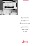
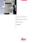
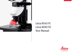
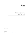
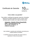
Leica
FluoCombi III™
User manual
Dear User,
Thank you for your confidence in our products. We trust you will enjoy them
and we wish you great success with the high-quality and high-performance
products from Leica Microsystems.
In developing our instruments, we place great value on simple, selfexplanatory operation. Nevertheless, please take the time to read the operating instructions so that you know the advantages and possibilities offered
by your stereomicroscope and can use them most efficiently. Should you
ever have any questions, please consult your local Leica representative.
We are gladly at your service. Customer service is a big thing with us. Not
only before the sale, but afterwards as well. You will find the address of
your nearest local representative, as well as valuable information about
Leica Microsystems products and services, from Leica Microsystems on
our web site at www.leica-microsystems.com.
Leica Microsystems (Switzerland) Ltd.
Stereo & Macroscope Systems
www.stereomicroscopy.com
Leica FluoCombi III™ – User manual
2
Overviews
8
3
5
6
7
4
9
1
Fig. 1 Leica FluoCombi IIITM, 5× planapo HR objective rotated into the beam path
Operating and function elements
1
2
3
4
5
3
Fine focusing with mount thread for a 5× or 20× HR objective (requires an adapter)
Clamping screw for locking the fine focusing
Mechanism for parcentric swinging to the stereo or micro mode
Slot for filter slide for dichroic mirror of your choice
Mount for UV protection screen
Leica FluoCombi III™ – Overviews
8
5
3
6
7
2
1
9
Fig. 2 Leica FluoCombi IIITM, 1× planapo objective rotated into the beam path
6
7
8
9
Clamping screw for fastening the UV protection screen
Clamping screw for locking the UV protection screen in the desired tilt position
Clamping screw for fastening the optics carrier in the microscope carrier of the FluoCombi III™
Clamping screw for fastening the focusing stop
Leica FluoCombi III™ – Overviews
4
Contents
Page
Overviews . . . . . . . . . . . . . . . . . . . . . . . . . . . . . . . . . .
Operating and function elements . . . . . . . . . . . . 3, 4
1. General notes . . . . . . . . . . . . . . . . . . . . . . . . . . 6
1.1 The user manual . . . . . . . . . . . . . . . . . . . . . . . . 6
1.1.1 Diagrams . . . . . . . . . . . . . . . . . . . . . . . . . . . . . . 6
1.2 Description . . . . . . . . . . . . . . . . . . . . . . . . . . . . 6
2. Assembly
2.1 Expansion diagram . . . . . . . . . . . . . . . . . . . . . . 7
2.2 Standard delivery . . . . . . . . . . . . . . . . . . . . . . . 8
2.2.1 Additional components . . . . . . . . . . . . . . . . . . 8
2.3 Assembly sequence . . . . . . . . . . . . . . . . . . . . . 9
2.4 Column with focusing drive
and base of stand . . . . . . . . . . . . . . . . . . . . . . 10
2.5 Focusing stop . . . . . . . . . . . . . . . . . . . . . . . . . 10
2.6 Transport anchorage . . . . . . . . . . . . . . . . . . . 11
2.7 FluoCombi III™ and focusing drive . . . . . . . 11
2.8 Optics carrier . . . . . . . . . . . . . . . . . . . . . . . . . 12
2.9 Objectives . . . . . . . . . . . . . . . . . . . . . . . . . . . . 13
2.10 UV protection screen . . . . . . . . . . . . . . . . . . . 14
2.11 Dichroic mirrors . . . . . . . . . . . . . . . . . . . . . . . 14
2.12 Illumination . . . . . . . . . . . . . . . . . . . . . . . . . . . .14
3. Operation
3.1 Parfocality . . . . . . . . . . . . . . . . . . . . . . . . . . . . 15
3.2 Magnification . . . . . . . . . . . . . . . . . . . . . . . . . 17
4.
4.1
4.2
4.3
4.4
Appendix
Weights . . . . . . . . . . . . . . . . . . . . . . . . . . . . . . 18
Dimensions . . . . . . . . . . . . . . . . . . . . . . . . . . .19
Optical data . . . . . . . . . . . . . . . . . . . . . . . . . . .22
Technical data . . . . . . . . . . . . . . . . . . . . . . . . .24
Leica FluoCombi III™ – User manual
5
1. General notes
1.1 The user manual
1.1.1 Diagrams
Leica FluoCombi III™ is an accessory for the
Leica MZ16 F, MZ16 FA fluorescence stereomicroscopes. Together with your Leica FluoCombi III™,
you receive an interactive CD-ROM with the user
manual for all products from Leica Microsystems
(Switzerland) in the current EU languages. User
manuals and updates are also available for you
to download and print from our web site at
www.stereomicroscopy.com. The following
user manuals are important for your
Leica FluoCombi III™:
Pages 3 and 4 contain figures showing the
Leica FluoCombi III™ with the function elements.
Numbers in parentheses within the descriptions
refer to the number of the figure and the items in
the figure.
Example (1.4): Figure 1 is located on page 3, and
the item 4 is the insert for dichroic mirrors.
– M2-166-2 Leica FluoCombi III™: It describes the
specific functions of the FluoCombi III™
– M2-160-4 for MZ16 FA and M2-160-5 for MZ16 F
describe the functions of the motorized and
the manual version
– M2-216-1 describes the lamp housing and
its functions
– M2-105-0 Leica M Stereomicroscopes: It
contains all the detailed information about the
use of the stereomicroscope, the optical data
with stereo objectives, and the safety and care
instructions
– M1-267-1 Leica motor focus system: describes
the motorized focusing
Read the user manuals listed
above before the startup procedure.
In particular, please follow the safety
instructions.
To maintain the unit in its original condition and to
ensure safe operation, the user must follow the
instructions and warnings contained in these user
manuals.
6
1.2 Description
Leica FluoCombi III™ is an accessory for the Leica
MZ16 F, MZ16 FA fluorescence stereomicroscopes
and allows for quickly switching between a stereo
objective and an HR (High Resolution) micro
objective. In stereo mode, the 1× plan and planapo
objectives offer generous viewing fields, large
working distances and an excellent depth of field
for manipulating and dissecting.
Micro mode allows for exactly identifying the
finest fluorescent features at a microscopic resolution of 1500 pairs of lines/mm. The zoom is also
effective in micro mode so that the magnification
measures 460× using the 5× HR objective. Using
16× eyepieces results in a maximum magnification
of 736×. The comfortable binocular observation is
ensured in stereo and micro mode.
MZ16 F and MZ16 FA are high-performance stereomicroscopes for fluorescence applications. The
patented, separate TripleBeam™ light path for
fluorescence illumination and the patented
FLUOIII™ filter system provide highest-quality
fluorescence images. Every existing instrument
can be fitted with the Leica FluoCombi III™ in a
few simple steps.
Leica FluoCombi III™ – General notes
2. Assembly
2.1 Expansion diagram
10 447 160
10 445 301
10 445 302
10 445 303
106z
11 504 066
11 504 069
10 446 271
10 446 229
10 445 822
MZ16 F
10 447 064
MZ16 FA
10 447 063
Filter
10 447 284
10 447 285
10 447 286
10 447 287
10 447 288
10 447 289
FluoCombi IIITM
10 447 324
Motor focus
10 447 041 500mm
10 447 290
10 447 291
10 447 292
10 447 293
10 447 294
10 447 295
10 447 338
10 445 819
10 447 157
Plan/Planapo
10 447 085 20x HR
Optem / Mitutoyo
10 447 243
5x HR
10 447 185 500mm
10 445 631
10 445 363
10 445 387
10 445 367 HL
10 446 352 HL RCTM
Leica FluoCombi III™ – Assembly
7
2.2 Leica FluoCombi III™ standard delivery
– Leica FluoCombi III™ with microscope carrier
(Fig. 3) for the MZ16 F and MZ16 FA optics carrier, mechanism for swinging into the stereo or
micro mode, fine focusing with mount thread
for an HR objective and for a 1× plan or planapo
objective
– UV protection screen (7.11)
– Focusing stop with stops (7.3)
– Column adapter (7.2a)
Fig. 3 Leica FluoCombi IIITM
2.2.1 Additional components
– HR planapo objective 5×/0.5 LWD (Fig. 4),
FAA 19mm or
– Adapter (5.1) for Mitutoyo/Optem objectives and
screw-in adapter (5.2) as well as the
corresponding objective
– Fluorescence stereomicroscope (7.5) with third
TripleBeam™ beam path, FLUOIII™ filter system, rapid filter changer and Leica lamp housing for mercury high-pressure lamps as well as
binocular tube, eyepieces, stand and focusing
drive
– 1× Plan or planapo objective (7.9)
– Dichroic mirror of your choice (Fig. 6)
Assembly and setup of Leica MZ16 F, MZ16 FA
fluorescence stereomicroscope and the fluorescence illumination are described in the respective
operating instructions (see p. 6).
Fig. 4 HR planapo objective 5×/0.5 LWD
1
2
Fig. 5 Adapter (1) for Mitutoyo/Optem objectives
and screw-in adapter (2)
Binocular tube, eyepieces, stands, mercury vapor
lamp, etc. are described in the operating instructions M2-105-0, M2-160-5, M2-160-4, M2-216-1.
Fig. 6 Dichroic mirror
8
Leica FluoCombi III™ – Assembly
13
7
6
12
5
4
2
11
8
3
9
2a
14
10
1
Fig. 7 Leica MZ16 F with Leica FluoCombi III™
2.3 Assembly sequence
1 Base of stand
2 Focusing drive with column (manual or
motorized) and column adapter (2a)
3 Focusing stop
4 Leica FluoCombi III™
5 Optics carrier
6 Binocular or video/photo tube and eyepieces
7 Lamp housing with high-pressure lamp and
stray-light protection
8 Supply unit
9 Plan or planapo objective 1×
10 HR planapo objective 5× (or adapter and
Mitutoyo/Optem objective)
11 UV protection screen
12 Filter sets upon demand in the filter
changer and analogous with a dichroic filter
in the FluoCombi III™
13 Photo equipment (if available)
14 Gliding stage or thermal stage (if available)
Leica FluoCombi III™ – Assembly
9
2.4 Column with focusing drive ➜ base of
stand
First, attach the column adapter between stand
column and base. It is used to ensure that the
center of the objective lies exactly over the center
of the stage.
Fasten the column adapter (8.1) with the
3 hexagon-head screws on the column.
Fasten the column with the column adapter on
the stand base according to the operating
instructions M2-105-0.
2
3
2.5 Focusing stop
1
The focusing stop is used for safety
purposes and must always be correctly set with
respect to the micro objective.
Fasten the focusing stop (8.2) to the column
with the clamping screw (8.3).
Fig. 8
1 Column adapter
2 Focusing stop
3 Clamping screw for fastening
the focusing stop
Set the focusing stop at a height so that
the micro objective can never hit the stand or
table surface or the object during focusing and
swinging. Working distance 5× HR objective:
19mm, 20× HR objective 13mm.
With a correctly set focusing stop, the two
stops prevent focusing too low, either manually or
motorized.
1
If the focusing stop is set too low
– the objective could be damaged.
– the object could be crushed or damaged.
– if the lowest focus position is approached too
quickly using the motor focus, the fingers of the
operator could be pinched between objective
and object.
Fig. 9 Leica FluoCombi III™ from below
1 Transport safety screws
10
Leica FluoCombi III™ – Assembly
1
2.6 Transport anchorage
2.7 FluoCombi III™ ➜ focusing drive
Remove transport locking screws (9.1) on both
sides of the FluoCombi III™ and screw them into
the respective threads for storing for transport at
a later time.
• The swinging mechanism is now released.
The Leica FluoCombi III™ must never be
unscrewed. All mechanical and optical components are exactly adjusted at the factory.
Always secure the FluoCombi III™ during
transport with these two transport safety screws.
Otherwise, the mechanism could be damaged
and maladjusted.
To attach the FluoCombi III™ on the focusing
drive, the mount thread for the stereo objective
must be turned to the observer. Only in this position is the thread accessible for mounting the
FluoCombi III™.
Turn the thread for the stereo objective (10.1) to
the observer by using the swinging mechanism.
Only in this position is the thread accessible for
mounting the FluoCombi III™ on the focusing
drive.
3
Fit in and hold FluoCombi III™ (10.2) in the two
plugs (at the back of the yoke, not visible in the
figure) on the focusing drive.
Insert the hexagon-head screw (10.3) through
the bore and tighten it on the focusing drive.
2
1
Fig. 10 Leica FluoCombi III™ from the front
1 Mount for stereo objective
2 Leica FluoCombi III™
3 Hexagon-head screw for fastening the
FluoCombi III™ on the focusing drive
Leica FluoCombi III™ – Assembly
11
2
1
3
7
6
4
5
Fig. 11 Leica FluoCombi III™ with Leica MZ16 F
1 Clamping screw for fastening
the optics carrier
2 MZ16 F, MZ16 FA optics carrier
3 Thread for plan or planapo objective 1×
12
4
5
6
7
Plan or planapo objective 1×
Thread for HR objective
Fine focusing
Clamping screw for fixing the fine focusing
Leica FluoCombi III™ – Assembly
2.8 FluoCombi III™ ➜ optics carrier
The optics carrier may not be laterally
rotated in the microscope carrier of the
FluoCombi III™ since the 3rd beam path of the
stereomicroscope and the FluoCombi III™ are
adjusted to each other.
Loosen the clamping screw (11.1) and remove
the dust cover in the microscope carrier of the
FluoCombi III™.
Carefully insert the optics carrier (11.2) in the
microscope carrier and align it so that the
optics carrier is flush with the microscope
carrier.
Tighten the clamping screw (11.1).
Turn the thread for the micro objective (11.5) to
the observer.
Hold the fine focusing (11.6) or lock it with the
clamping screw (11.7).
Tighten the 5× HR objective counterclockwise
in the thread mount.
OR
Tighten the adapter (13.1) for Mitutoyo/Optem
objectives and in the thread (6.5) using the
screw-in adapter (13.2).
Tighten the corresponding objective at the
adapter (13.1).
The assembly of the remaining components is
similar to the binocular tube, eyepieces, etc., see
M2-105-0, and the fluorescence illumination, see
M2-160-0.
2.9 Objectives
FluoCombi III™ is adjusted so that the focused
position remains sharp (parfocal) and centered
(parcentric) with every zoom position if used
with a 1× plan or planapo objective and a 5× or
20× HR objective in the stereo and micro mode.
Fig. 12 HR planapo objective 5×
1
Hold the objectives during assembly and disassembly so that they do not fall onto the stage plate.
Remove specimens from the stage plate.
2
Turn the thread for the stereo objective (11.3) to
the observer by using the swinging mechanism.
Tighten the 1× plan or planapo objective (11.4)
counterclockwise in the thread mount.
Fig. 13
1 Adapter for Mitutoyo/Optem objectives
2 Screw-in adapter
Leica FluoCombi III™ – Assembly
13
2.10 UV protection screen
2.11 Dichroic mirrors
Never work without UV protection
screen!
Fasten the holder with UV protection screen
(14.1) at the mount (14.2) using the clamping
screw (14.3).
Loosen the clamping screw (14.4).
Tilt the UV protection screen (14.1) so that the
operator cannot look directly onto the light spot.
Tighten the clamping screw (14.4).
2
3
4
5
Use dichroic mirrors (2-color-coated) in the FluoCombi III™ analogous to the filter sets used in the
filter changer of the stereomicroscope. The mount
of the dichroic mirror is magnetically fixed in the
mount to ensure a correct alignment.
Insert the mount with the dichroic mirror (Fig. 6) in
the slot for the filter slide (14.5) so that the guide
pin points down and the marking can be read on
the outside.
Dichroic mirror
marking
GFP
GFP Plus
GFP Plant
UV
Blue
Green
Texas Red
CFP
YFP
DsRED
GFP1
GFP2
GFP3
UV
B
G
TXR
CFP
YFP
DSR
1
2.12 Illumination
Please adjust the Hg lamp precisely
according to the M2-160-0 operating instructions
so that you can achieve a homogenous light spot
and good fluorescence even in micro mode.
Fig. 14 UV protection screen
1 UV protection screen with holder
2 Mount for UV protection screen
3 Clamping screw for fastening the
UV protection screen
4 Clamping screw for locking the
UV protection screen in the desired tilt
5 Slot with dichroic mirror
14
Leica FluoCombi III™ – Assembly
3. Operation
3.1 Setting the parfocality
If a 1× plan or planapo objective and a 5× or
20× HR objective is used, the focused position in
stereo and micro mode remains sharp (parfocal)
and centered (parcentric) with every zoom position. For this reason, it is important to adjust the
parfocality precisely as described.
• We recommend performing the diopter setting
in transmitted or incident light. If the fluorescence illumination is activated, block the light
using the light stop and rotate the dummy filter
carrier into the beam path.
• Use a very fine, flat object that can still be
focused with precision at the highest magnification.
• Zooming, focusing and adjusting interpupillary
distance, eyecups, diopter settings, working
distance, illumination see M2-105-0 or M2-160-4
(MZ16 FA) and M2-160-5 (MZ16 F) operating
instructions.
The following settings must be performed by every
user only once.
Leica FluoCombi III™ – Operation
15
3.1.1. Stereo mode
Ensure that the focusing stop (15.4) is set
so that the micro objective can never hit the stand
or table surface or the object during focusing and
swinging (see Chapter 2.5).
Swing the 1× plan or planapo objective (15.1) to
the observer.
Set the eye lenses at both eyepieces to diopter
setting «0».
Select the lowest zoom setting.
Set the working distance (15.2) with the coarse
focusing drive: 60mm for 1× plan, 55mm for
1× planapo.
Observe a flat test object and focus with fine
focusing drive.
Select the highest zoom setting.
Optimize the image sharpness.
Rotate the eye lenses counterclockwise in the
direction of «+» until the stop (+5 diopter setting).
Do not look into the eyepieces during the procedure.
Select the lowest zoom setting.
Look into the eyepieces and close one eye
each. Observe the test object with one eye and
slowly rotate the eye lense at the respective
eyepiece clockwise in the direction of «–» until
the view of the test object is sharp.
Repeat the same for the other eye.
Checking the parfocality:
4
1
Select the highest zoom setting.
Observe the test object with both eyes and
adjust the focus, if necessary.
Check the image sharpness from the lowest to
the highest zoom position.
• The image sharpness must remain constant
(parfocal). If this is not the case, repeat the
procedure.
2
3
Fig. 15 Planapo objective 1× rotated into the
beam path
1 Planapo objective 1×
2 Working distance
3 HR planapo objective 5×
4 Focusing stop
16
Leica FluoCombi III™ – Operation
3.1.2. Micro mode
3.2 Magnification, field of view
Swing the HR objective (16.1) to the observer.
Select the lowest zoom setting.
Sharply focus the object with fine focusing
(16.2).
Working distance with 5× HR objective: 19mm
and with 20× HR objective 13mm.
Refocus little by little and continuously up to the
highest zoom position.
Lock the fine focusing with the clamping screw,
if needed, to avoid unintentional adjustment
changes.
The magnification changer is effective in stereo
and micro mode. Magnification factors of the
micro objectives with Leica:
• HR objective 5×: 4×
• HR objective 20×: 8×
The table with the optical data is located
on page 22.
The focused position now remains sharp (parfocal) and centered (parcentric) in stereo and micro
mode for every zoom position.
1
2
3
Fig. 16 HR planapo objective 5× rotated into the
beam path
1 HR planapo objective 5×
2 Fine focusing
3 Planapo objective 1×
Leica FluoCombi III™ – Operation
17
4. Appendix
4.1 Weights
FluoCombi III™
HR planapo objective 5×
HR objective 10×
HR objective 20×
Planapo objective 1×
Plan objective 1×
3.220kg
0.5kg
0.2kg
0.2kg
0.74kg
0.78kg
Leica MZ16 F optics carrier
Leica MZ16 FA optics carrier
Optics carrier
3.420kg
3.14kg
3.82kg
ErgoTube™ 10°–50°
Trinocular video/photo tube 100%
Wide-field eyepieces for persons
wearing glasses 10×/21B
GFP filter set
UV filter set
Lamp housing 106Z for 50 W
Lamp housing 106Z for 100 W
Hg lamp 50 W
Hg lamp 100 W
Stray-light protection
1.7kg
1.595kg
18
0.158kg
0.04kg
0.06kg
2.26kg
2.4kg
0.1kg
0.08kg
0.58kg
Leica FluoCombi III™ – Operation
4.2 Dimensions
HR planapo objective 5×
Leica FluoCombi III™ – Appendix
19
Leica FluoCombi IIITM
Dimensions in mm
20
Leica FluoCombi III™ – Appendix
201.8
105.84
100
30
10
32.5
1
10.5
33
35
Ø5.5
6 +0.03
0
M42 Ph3P1
M42 Ph3P1
131
90
Ø76 H7
M65×1.5
30
Dimensions in mm
Leica FluoCombi III™ – Appendix
21
4.3 Optical data
Leica MZ16 F and MZ16 FA
Objective
Planapo 5×/0.5 (10447243)
Factor
4×
Iris diaphragm open
Working distance 19.8mm
Eyepiece
Zoom
position
0.71
1
1.6
2
2.5
3.2
4
5
6.3
8
10
11.5
22
10×/21B
Total
magnification
28.4×
40×
64×
80×
100×
128×
160×
200×
252×
320×
400×
460×
Field of view
diameter
(mm)
Numerical
aperture
Resolution
(lp/mm)
Visible
structure width
(µm)
1.6
1.6
1.6
1.6
1.6
1.6
1.31
1.05
0.83
0.66
0.53
0.46
0.084
0.11
0.17
0.2
0.24
0.3
0.34
0.4
0.45
0.49
0.5
0.5
252
336
504
612
732
888
1032
1200
1344
1488
1500
1500
3.97
2.98
1.98
1.63
1.37
1.13
0.97
0.83
0.74
0.67
0.67
0.67
Leica FluoCombi III™ – Appendix
Eyepiece 16×/14B
Zoom
position
Total
magnification
Field of view
diameter
(mm)
Numerical
aperture
Resolution
(lp/mm)
Visible
structure width
(µm)
0.71
45.4×
1.6
0.08
252
3.97
1
64×
1.6
0.11
336
2.98
1.6
102×
1.6
0.17
504
1.98
2
2.5
128×
160×
1.6
1.4
0.20
0.24
612
732
1.63
1.37
3.2
205×
1.1
0.3
888
1.13
4
5
6.3
8
10
11.5
256×
320×
403×
512×
640×
736×
0.87
0.7
0.56
0.44
0.35
0.3
0.34
0.4
0.45
0.49
0.5
0.5
1032
1200
1344
1488
1500
1500
0.97
0.83
0.74
0.67
0.67
0.67
Leica FluoCombi III™ – Appendix
23
4.4 Technical data
Leica FluoCombi III™
Type
Optics
Mechanics
Parfocal / parcentric
Fine focusing
Dichroic mirrors
Accessories with quick changer for Leica fluorescence stereomicroscopes
MZ16 FA, MZ16 F, for a stereomicroscope objective (3D-view) and an
HR objective (microscopic resolution)
Multiple-coated high-performance optics, lead-free, maximum resolution
with micro objective; beam splitter for binocular observation
360° rotation and lateral movement, TripleBeamTM, fine focusing,
safety focus stop
– Objective change between 1× plan or planapo and 5× HR objectives
at constant image sharpness
– adjustable fine focusing for micro objective
integrated
GFP, GFP+, GFP Plant, UV, Blue, Green, CFP, YFP, Texas Red, DsRed, CY5, CY7,
magnetically fixed
Micro objectives
HR planapo 5×
with MZ16 F / MZ16 FA
– Numerical aperture: 0.5
– Resolution: 1500 Lp/mm
– Finest visible structure width 0.3µm
– Working distance: 19mm
– Magnification factor: 4×
– Magnification: 460× with 10× eyepieces
– 736× with 16× eyepieces
Adapter
For Mitutoyo/Optem objectives
Fluorescence stereomicroscopes
Designation
– Leica MZ16 F with 16:1 zoom
– Leica MZ16 FA, motorized, with 16:1 zoom
Microscope type
Stereomicroscopes with patented TripleBeam® third beam path and
patented FLUOIII® fluorescence filter system, lead-free glass
Rapid filter changer
horizontal FLUOIII® quick changer for 4 filter sets
Fluorescence filters
– Excitation and suppression filter sets: GFP, GFP+, GFP Plant, UV, Blue,
Green, CFP, YFP, TXR, DSR, Cy3™, Cy5™
– Slot for filter slide for neutral density filters
Illumination
– TripleBeam®: 3rd beam path for fluorescence light
– 100-W or 50-W high-pressure lamp, chromatically corrected collector,
focusable, lamp mount can be centered
Extensive
UV protection screen, UV barrier filter, stray-light protection for lamp housing
UV protection
and dummy filter carrier for empty filter positions
Stereo objective
1× planapo or plan: 0.125 NA, 2.7µm resolution
2× planapo: 0.25 NA, 1.3µm resolution, 750 Lp/mm
Working distance
60mm (1× plan), 55mm (1× planapo), 15mm ( 2× planapo)
(stereo)
Eyepieces
Ergonomic wide-field eyepieces for eyeglass wearers 10×/21, 16×/14 with
high field number, distortion-free, lead-free glass
24
Leica FluoCombi III™ – Appendix
Accessories
Ergonomics
Stands
Specialty stages
Accessories
– Apochromatic ErgoTube® with variable viewing angle 10°–50°
– ErgoWedge® 5°–25°
– Trinocular tube
– Motor focusing system with 0.7µ resolution
– Gliding stage
– High-performance transmitted-light base HL RC™
– Transmitted-light bases bright field/dark field
– Incident-light bases
– Anti-vibration platform
– 500mm focusing drive, coarse/fine with 1µ resolution
– Gliding stage
– Thermocontrol System Leica MATS
– FireWire digital camera systems for fluorescence
– Analog and video cameras
– Image processing and analysis software (IM1000, FW4000, QWin)
– Measurement graticules
Leica FluoCombi III™ – Appendix
25
Leica Microsystems – the brand
for outstanding products
Leica, the leading brand for microscopes and scientific instruments, developed from
five brand names, all with a long tradition: Wild, Leitz, Reichert, Jung and Cambridge
Instruments. Yet Leica symbolizes innovation as well as tradition.
Leica Microsystems – an international company
with a strong network of customer services
Australia:
Austria:
Canada:
China:
Denmark:
France:
Gladesville, NSW
Vienna
Richmond Hill/Ontario
Hong Kong
Herlev
Rueil-Malmaison
Cédex
Bensheim
Milan
Tokyo
Seoul
Rijswijk
Lisbon
Germany:
Italy:
Japan:
Korea:
Netherlands:
Portugal:
Singapore:
Spain:
Barcelona
Sweden:
Sollentuna
Switzerland:
Glattbrugg
United Kingdom: Milton Keynes
USA:
Bannockburn/Illinois
Tel.
Tel.
Tel.
Tel.
Tel.
+1 800 625 286
+43 1 486 80 50 0
+1 905 762 20 00
+8522 564 6699
+45 44 5401 01
Fax
Fax
Fax
Fax
Fax
+61 2 9817 8358
+43 1 486 80 50 30
+1 905 762 89 37
+8522 564 4163
+45 44 5401 11
Tel.
Tel.
Tel.
Tel.
Tel.
Tel.
Tel.
Tel.
Tel.
Tel.
Tel.
Tel.
Tel.
+33 1 4732 8585
+49 6251 1360
+39 02 57 486 1
+81 3 543 596 09
+82 2 514 6543
+31 70 41 32 130
+35 1 213 814 766
+65 6 77 97 823
+34 93 494 9530
+46 8 625 45 45
+41 44 809 34 34
+44 1908 246 246
+1 800 248 0123
Fax
Fax
Fax
Fax
Fax
Fax
Fax
Fax
Fax
Fax
Fax
Fax
Fax
+33 1 4732 8586
+49 6251 136 155
+39 02 5740 3273
+81 3 543 596 15
+82 2 514 6548
+31 70 41 32 109
+35 1 213 854 668
+65 6 77 30 628
+34 93 494 9532
+46 8 625 45 10
+41 44 809 34 44
+44 1908 609 992
+1 847 405 0164
and representatives of Leica Microsystems
in more than 100 countries.
In accordance with the ISO 9001 certificate, Leica Microsystems (Switzerland) Ltd,
Business Unit Stereo & Macroscope Systems has at its disposal a management system
that meets the requirements of the international standard for quality management. In
addition, production meets the requirements of the international standard ISO 14001 for
environmental management.
Leica Microsystems (Switzerland) Ltd
Stereo & Macroscope Systems
CH-9435 Heerbrugg
Telephone +41 71 726 33 33
Fax +41 71 726 33 99
www.leica-microsystems.com
www.stereomicroscopy.com
The companies of the Leica Microsystems
Group operate internationally in four business
segments, where we rank with the market
leaders.
●
Microscopy Systems
Our expertise in microscopy is the basis for all
our solutions for visualization, measurement
and analysis of microstructures in life sciences
and industry. With confocal laser technology
and image analysis systems, we provide threedimensional viewing facilities and offer new
solutions for cytogenetics, pathology and materials sciences.
●
Specimen Preparation
We provide comprehensive systems and services for clinical histo- and cytopathology
applications, biomedical research and industrial quality assurance. Our product range
includes instruments, systems and consumables for tissue infiltration and embedding,
microtomes and cryostats as well as automated stainers and coverslippers.
●
Medical Equipment
Innovative technologies in our surgical microscopes offer new therapeutic approaches in
microsurgery.
●
Semiconductor Equipment
Our automated, leading-edge measurement and
inspection systems and our E-beam lithography
systems make us the first choice supplier for
semiconductor manufacturers all over the world.
Illustrations, descriptions and technical data are not binding and may be changed without notice.
M2-166-2en • © Leica Microsystems (Switzerland) Ltd. • CH-9435 Heerbrugg, 2004 • Printed in Switzerland – en – XI.2004 – RDV
Leica Microsystems’ mission is to be the world’s first-choice provider of innovative
solutions to our customers’ needs for vision, measurement, lithography and analysis
of microstructures.