1
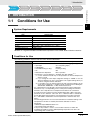
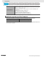
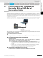
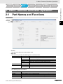
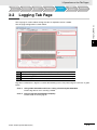
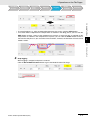
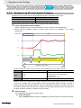
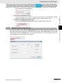
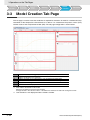
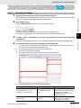
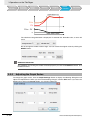
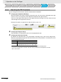
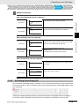
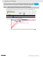
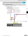
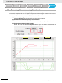
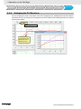
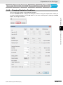
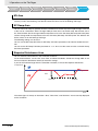
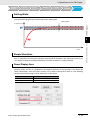
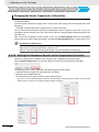
1 Introduction 2 Basic Thermac Simulator Operation Thermac Simulator 3 Operations on the Tab Pages 4 Operation Manual Appendix I Index H190-E1-01 CONTENTS Introduction Overview.................................................................................................................... 3 Features..................................................................................................................... 3 IMPORTANT............................................................................................................... 4 Software License Agreement .................................................................................. 4 Section 1. Definitions .....................................................................................................................................4 Section 2. Permitted Uses .............................................................................................................................4 Section 3. Prohibited Uses ............................................................................................................................5 Section 4. No Warranty and Disclaimer .........................................................................................................5 Section 5. Damage Limitation ........................................................................................................................5 Section 6. Intellectual Property Ownership Rights ........................................................................................6 Section 7. Modifying the Software .................................................................................................................6 Section 8. Confidential Information ................................................................................................................6 Section 9. Expiration and Termination of this Agreement .............................................................................6 Section 10. Indemnification ...........................................................................................................................6 Section 11. Miscellaneous .............................................................................................................................7 Section 12. Governing Law and Settlement of Disputes ...............................................................................7 Precautions for Safe Use ......................................................................................... 8 Precautions for Correct Use .................................................................................... 8 Revision History ....................................................................................................... 9 Related Manuals ..................................................................................................... 10 Section 1 Introduction 1-1 Conditions for Use................................................................................................................... 1-1 1-2 Connecting to the Temperature Controller with a USB-Serial Conversion Cable ............. 1-3 Section 2 Basic Thermac Simulator Operation 2-1 Part Names and Functions ..................................................................................................... 2-1 2-2 Files .......................................................................................................................................... 2-2 2-3 Basic Operations ..................................................................................................................... 2-3 Section 3 3-1 Operations on the Tab Pages Settings Tab Page.................................................................................................................... 3-1 3-1-1 3-1-2 3-1-3 3-2 Using a New Controller............................................................................................................... 3-2 Using a Previously Set Controller ............................................................................................... 3-3 Using a Log File from Another Company.................................................................................... 3-3 Logging Tab Page .................................................................................................................... 3-5 3-2-1 3-2-2 Collecting Log Data .................................................................................................................... 3-6 Reading a Log File from Another Company ............................................................................... 3-8 Thermac Simulator Operation Manual (H190) 1 3-2-3 3-3 Model Creation Tab Page ...................................................................................................... 3-10 3-3-1 3-3-2 3-4 Creating the Model.................................................................................................................... 3-11 Adjusting the Graph Scales....................................................................................................... 3-12 PID Simulation ....................................................................................................................... 3-13 3-4-1 3-4-2 3-4-3 3-4-4 3-4-5 3-4-6 3-4-7 3-4-8 3-4-9 3-4-10 Section 4 Adjusting the Graph Scales......................................................................................................... 3-9 Adjusting the PID Constants ..................................................................................................... 3-14 Executing Autotuning (AT)......................................................................................................... 3-15 Adjusting the Rising Portion of the PV Waveform ..................................................................... 3-16 Changing the Set Point ............................................................................................................. 3-17 Comparing Waveforms during Adjustment................................................................................ 3-18 Checking Waveform Information ............................................................................................... 3-19 Adjusting the Graph Scales....................................................................................................... 3-19 Enlarging the PV Waveform ...................................................................................................... 3-20 Changing Simulation Conditions ............................................................................................... 3-21 Writing the Simulation Results to the Temperature Controller .................................................. 3-24 Appendix Phase Changes during Log Data Collection ............................................................................... 4-1 Index 2 Thermac Simulator Operation Manual (H190) Overview Introduction Overview The Thermac Simulator is a software application that simulates temperature control for E5C-series Temperature Controllers. Features Adjusting parameters for a Temperature Controller can require extensive time because the equipment has to be operated and the control results have to be checked. The Thermac Simulator, however, allows you to simulate equipment temperatures on a computer, so that adjustment results can be checked immediately without operating the equipment. With just the Thermac Simulator, you can perform everything from parameter settings and log data collection through the actual simulations. Functions are also provided to allow you to easily adjust the parameters, such as automatic optimal differential time (D) adjustment and simulation results comparison before and after adjustment. Thermac Simulator Operation Manual (H190) 3 IMPORTANT IMPORTANT By installing this Software, User is deemed to agree to be bound by the following Software License Agreement. If User does not agree the following Software License Agreement, User cannot download and use Software and have to immediately stop installing or downloading Software. Software License Agreement This is a binding agreement between User and OMRON Corporation, a corporation organized and existing under the laws of Japan with its place of business at Shiokoji Horikawa, Shimogyo-ku, Kyoto, Japan (“OMRON”) on the terms and conditions to use Software. Section 1. Definitions “Software” means the computer program and related documentation for temperature controllers typed E5C series contained in this package, including, without limitation, revision software, updates and other derivative works thereto. “User” means a corporation, company, partnership and other entity for the use of which its employee, staff, member, agent or other third party downloads or obtains Software. “Intellectual Property Rights” means any patent, copyright, trade secret, trademark or other intellectual property rights (including, without limitation, applications thereof) in any idea, design, concept, method, technique, invention, discovery, improvement, technical information, software (in whatsoever form or media) and related algorithms, flow charts, logic diagrams and specifications, mask works, graphics or other works of authorship. “Affiliated Companies” means any company, corporation or entity that is controlled by a party and/or any company, corporation or entity that controls a party and/or any company, corporation or entity that is controlled by one of the before mentioned companies, corporations or entities. However, any such company, corporation or entity shall be deemed to be an Affiliated Companies only as long as control exists. For these purposes, a company, corporation or entity shall be treated as being controlled by another company, corporation or entity if that other company, corporation or entity has fifty percent (50%) or more of the votes in such entity, and/or is able to direct its affairs and/or to control the composition of its board of directors or equivalent body. Section 2. Permitted Uses Subject to the terms and conditions in this Agreement, OMRON grants User a non-exclusive, non-transferable and royalty-free license to use Software on computers owned by User for the purpose of simulating parameter for temperature controllers of OMRON or its Affiliated Company. 4 Thermac Simulator Operation Manual (H190) Software License Agreement Section 3. Prohibited Uses Without the prior written consent of OMRON, User shall not: (a) publish, disclose, market, sublicense, upload, rent, lease or distribute Software; (b) modify, translate, adapt, reverse engineer, de-compile or disassemble Software; (c) assign Software to a third party; or, (d) use, reproduce or otherwise utilize Software, in whole or in part, other than as expressly permitted by this Agreement. Section 4. No Warranty and Disclaimer OMRON LICENSES SOFTWARE TO USER “AS IS” BASIS WITH ALL FAULTS, AND WITHOUT WARRANTY OF ANY KIND. USER ACKNOWLEDGES AND AGREES THAT USER SHALL USE SOFTWARE SOLELY ON ITS OWN RESPONSIBILITY, AND AT ITS SOLE COST AND RISK. OMRON DOES NOT MAKE, AND HEREBY DISCLAIM, ANY EXPRESS OR IMPLIED WARRANTIES INCLUDING, BUT NOT LIMITED TO, TITLE AND NONINFRINGEMENT OF THIRD PARTY’S RIGHTS, THE WARRANTY OF DESIGN, ANY IMPLIED WARRANTY OF MERCHANTABILITY OR FITNESS FOR A PARTICULAR PURPOSE. OMRON DOES NOT WARRANT THAT SOFTWARE AND ITS OUTPUT WILL MEET USER’S REQUIREMENTS THAT ITS OPERATION WILL BE UNINTERRUPTED OR ERROR-FREE, THAT ITS DEFECTS WILL BE CORRECTED, OR THAT IT WILL BE COMPATIBLE WITH ANY OR FUTURE OMRON PRODUCTS. NO ORAL OR WRITTEN INFORMATION OR ADVICE GIVEN BY OMRON, ITS AFFILIATED COMPANIES OR ANY OF THEIR RESPECTIVE DIRECTORS, OFFICERS, EMPLOYEES OR AGENTS SHALL CREATE A WARRANTY OR IN ANY WAY INCREASE THE SCOPE OF OMRON’S OBLIGATIONS UNDER THIS AGREEMENT. USER HEREBY WAIVE ANY AND ALL CLAIMS THAT USER MAY HAVE AGAINST OMRON, ITS AFFILIATED COMPANIES OR ANY OF THEIR RESPECTIVE DIRECTORS, OFFICERS, EMPLOYEES OR AGENTS ARISING OUT OF SOFTWARE AND/OR THIS AGREEMENT. Section 5. Damage Limitation SOFTWARE IS PROVIDED AS A CONVENIENCE AND ACCOMMODATION TO USER. TO THE EXTENT NOT PROHIBITED BY LAW, IN NO EVENT SHALL OMRON, ITS AFFILIATED COMPANIES OR ANY OF THEIR RESPECTIVE DIRECTORS, OFFICERS, EMPLOYEES, OR AGENTS, BE LIABLE TO USER OR ANY THIRD PARTY FOR ANY CAUSE OR CLAIM WHATSOEVER, INCLUDING PERSONAL INJURY, OR ANY INCIDENTAL, SPECIAL, INDIRECT, CONSEQUENTIAL OR PUNITIVE DAMAGES WHATSOEVER, INCLUDING, WITHOUT LIMITATION, DAMAGES FOR LOSS OF PROFITS, LOSS OF DATA, BUSINESS INTERRUPTION OR ANY OTHER COMMERCIAL DAMAGES OR LOSSES, ARISING OUT OF OR RELATED TO THIS AGREEMENT OR THE SOFTWARE, ITS OUTPUT, SECURITY SOLUTION OR SERVICES, HOWEVER CAUSED, WHETHER UNDER A THEORY OF CONTRACT, WARRANTY, TORT, NEGLIGENCE, PRODUCT LIABILITY, OR OTHERWISE, EVEN IF OMRON HAS BEEN ADVISED OF THE POSSIBILITY OF SUCH DAMAGES, AND NOTWITHSTANDING THE FAILURE OF ESSENTIAL PURPOSE OF ANY REMEDY. IN ANY EVENT, THE MAXIMUM LIABILITY OF ANY OF THE FOREGOING PARTIES FOR ALL CLAIMS OF EVERY KIND (INCLUDING THOSE ARISING IN TORT) ARISING OUT OF THE SOFTWARE AND/OR THIS AGREEMENT SHALL NOT EXCEED FIFTY U.S. DOLLARS (US$50.00). Thermac Simulator Operation Manual (H190) 5 Software License Agreement Section 6. Intellectual Property Ownership Rights Title and ownership of all Intellectual Property Rights in Software will at all times remain with OMRON or the third party who has licensed Software to OMRON, as the case may be. The rights granted to User by OMRON under such Intellectual Property Rights are only for the purposes set forth expressly in this Agreement. User shall not remove any copyright, patent, trade secret, proprietary and/or other legal notices contained on or in the Software, including any associated software, programming, or documentation. User shall not use any information or data disclosed by OMRON in connection with this Agreement to contest the validity of any Intellectual Property Rights of OMRON. Any such use of OMRON’s information and data shall constitute a material, non-curable breach of this Agreement. User shall not use Software and any Confidential Information disclosed by OMRON to User in connection with this Agreement to contest the validity of any Intellectual Property Rights of OMRON, including Software. Any such use of OMRON’s information and data shall constitute a material, non-curable breach of this Agreement. Section 7. Modifying the Software (1) OMRON may extend, enhance, or otherwise modify Software at any time without notice, but OMRON has no obligation to provide User with any updates or changes. (2) OMRON has no obligation to provide any support or engineering assistance of any sort to User. Section 8. Confidential Information User shall treat any information contained in the Software (“Confidential Information”) as confidential and shall not disclose it to any third party. This obligation shall survive after the termination of this Agreement. Section 9. Expiration and Termination of this Agreement This Agreement shall come into effect on the day first above written and remain valid for one (1) year thereafter. Unless either party notifies the other party of its intention not to renew this Agreement at least thirty (30) days prior to the expiration of then current term, this Agreement shall be automatically renewed and remain valid for a successive period of one (1) year thereafter each. If User breaches this Agreement, OMRON may terminate this Agreement upon notice to User. When this Agreement is expired or terminated, User shall promptly return or destroy the Software, Confidential Information and all copies thereof. The rights and obligations under Section 4, 5, 6, 8, 9, 10, 11 and 12 shall survive expiration or termination of this Agreement and bind the parties and their legal representatives, successors and assigns thereafter. Section 10. Indemnification User agrees to indemnify, defend and hold harmless OMRON, its Affiliated Companies and any of their directors, officers, employees or agents (collectively, the “OMRON Indemnitees”) from actual or alleged claims, losses, liabilities, damages, expenses and costs, including reasonable attorneys fees and expert costs, incurred by any OMRON Indemnitees as a result of (a) a breach of this Agreement by User, (b) User’s violation of applicable law, or (c) the negligence or other wrongful conduct of User. 6 Thermac Simulator Operation Manual (H190) Software License Agreement Section 11. Miscellaneous Neither this Agreement nor any part or portion hereof shall be assigned, sub-licensed or otherwise transferred by User. OMRON may assign this Agreement, without the User’s consent, to any Affiliated Companies or other third parties. Should any provision of this Agreement be held to be void, invalid, unenforceable or illegal by a court, the validity and enforceability of the other provisions of this Agreement shall not be affected thereby. Failure of a party to enforce any provision of this Agreement shall not constitute or be construed as a waiver of such provision or of the right to enforce such provision. Section 12. Governing Law and Settlement of Disputes The formation, validity, construction and the performance of this Agreement, and all amendments and supplements hereto, shall be governed and interpreted by and in accordance with the laws of Japan without reference to conflict of law rules. Any and all disputes, controversies or differences which may arise between the parties hereto out of or in relation to or in connection with this Agreement shall be finally and exclusively settled by the competent court of Kyoto, Japan. (C) Copyright OMRON CORPORATION 2004-2014 All Rights Reserved Thermac Simulator Operation Manual (H190) 7 Precautions for Safe Use Precautions for Safe Use • In addition to this manual, also refer to the Instruction Manual and User’s Manual for the Temperature Controller. • Check the destination Temperature Controller before you transfer the parameters to it. • Occasionally there are large deviations in the simulation waveforms. When you perform actual temperature control, always implement measures to ensure safety for unexpected temperature increases. Precautions for Correct Use • Use the Thermac Simulator only on the specified operating system. The Thermac Simulator may malfunction on other operating systems. • Do not use the Thermac Simulator near motors, power lines, or other sources of electrical noise. Noise may enter on communications cables, possibly causing malfunctions. • Do not run any other software applications while you are using the Thermac Simulator. Doing so may cause log data sampling to be skipped during communications with the Temperature Controller or other communications errors may occur. 8 Thermac Simulator Operation Manual (H190) Revision History Revision History A manual revision code appears as a suffix to the catalog number on the front cover of the manual. Cat. No. H190-E1-01 Revision code Revision code 01 Date July 2014 Thermac Simulator Operation Manual (H190) Revised content Original production 9 Related Manuals Related Manuals Refer to the E5C Digital Temperature Controller User’s Manual (Cat. No. H174) for information on the Temperature Controller and to the Instruction Manual that comes with the Temperature Controller for information on the USB-Serial Conversion Cable. 10 Thermac Simulator Operation Manual (H190) 1 Introduction Conditions for Use Connecting the Computer and Controller Basic Thermac Simulator Operation Settings Logging Model Creation Simulation 1-1 Conditions for Use 1 Introduction 1-1 Conditions for Use 1 System Requirements The following system requirements must be met to use the Thermac Simulator. Item OS Processor RAM Hard disk space CD-ROM drive Monitor Communications port Specification Microsoft Windows 7, 32-bit edition 1 GHz min., 32-bit (x86) or better processor 1 GB min. 16 GB or more available space 1 drive min. XGA (1,024 × 768), 16-bit high color or better 1 USB port min. Windows is a registered trademark of Microsoft Corporation in the United States and other countries. Conditions for Use The following conditions must be met to use the Thermac Simulator. Applicable Controllers E5C-series Temperature Controllers except for Position-proportional and Programmable Models 1. The Thermac Simulator cannot be used with any of the following settings. • • • • • Temperature Controller settings 2. 3. 4. 5. Thermac Simulator Operation Manual (H190) Input Type: PIDON/OFF: Standard/Heating-Cooling: ST: Direct/Reverse Operation: 25 to 29 (analog input)*1 ON/OFF Heating-Cooling ON Direct operation • Event Input 1 to 6 Assignments: Anything other than “NONE”*2, *3 *1 Correct simulation results may not be possible if an Infrared Temperature Sensor is used. *2 If you change the event input assignment settings to “NONE” to use the Thermac Simulator, be sure to return them to the original settings when you are done using the Thermac Simulator. *3 If a work bit is set as an internal event in the logic operation settings, set the event input assignment to anything except Communications Writing Enable/Disable, RUN/STOP, or 100% AT Execute/Cancel. For a Temperature Controller with a position-proportional output, temperature fluctuations may occur depending on the control period setting. The Thermac Simulator cannot reproduce those temperature fluctuations in a simulation. A model cannot be created correctly if the MV Upper Limit or MV Lower Limit parameter is set to between 5.0% and 0.1% or between 100.1% and 105.0%. Set the MV Upper Limit parameter of the Temperature Controller to between 0.1% and 100.0% and the MV Lower Limit parameter to between 0.0% and 99.9%. The following parameters are not used in simulations. The default settings of the Temperature Controller are used by the Thermac Simulator for these parameters. • Minimum Output ON/OFF Band: 1.0% • MV Change Rate Limit: 0.0%/s It may not be possible to create a correct model for devices for which the manipulated variable increases gradually during temperature rise due to SP ramp settings with a small slope. 1-1 1 Introduction Conditions for Use Connecting the Computer and Controller Controlled Devices Basic Thermac Simulator Operation Settings Logging Model Creation Simulation For the following controlled devices, there will be a large temperature deviation between a simulation and the actual Temperature Controller. Therefore the Thermac Simulator cannot be used for them. • Heaters for which there is a large change in the resistance depending on the temperature • Devices for which boiling or melting occurs • Cooling devices that use direct operation • Devices for which there is high thermal interference • Devices that reach the set point in 10 s or less • Devices that have a set point near room temperature Applicable Log Files from Other Companies The Thermac Simulator can read log files created by the following software applications. Temperature Controllers SDC15/25/26 (Azbil Corporation) RB00 (RKC Instrument Inc.) Application SLP-C35 Smart Loader Package PROTEM2 Company names and product names in this document are the trademarks or registered trademarks of their respective companies. 1-2 Thermac Simulator Operation Manual (H190) 1 Introduction 1-2 Basic Thermac Simulator Operation Connecting the Computer and Controller Settings Logging Model Creation Simulation Connecting to the Temperature Controller with a USB-Serial Conversion Cable To collect log data from the Temperature Controller, connect the Temperature Controller to the computer with an E58-CIFQ2 USB-Serial Conversion Cable. The E58-CIFQ2-E is required to connect to the Setup Tool port on the front panel of the E5EC, E5AC, or E5DC, or to connect to the Setup Tool port on the bottom panel of the E5GC. For details on connecting the Temperature Controller to the computer with an E58-CIFQ2 USB-Serial Conversion Cable, refer to the E5C Digital Temperature Controllers User’s Manual (Cat. No. H174). USB E5C Serial port E58-CIFQ2 USB-Serial Conversion Cable You must install a driver for the cable in the computer. If you are using the CX-Thermo, then the driver installation procedure is not required. Use the following procedure to install the driver. 1 2 Connect a USB port on the computer with a Setup Tool port on the Temperature Controller using the Cable. Install the driver that comes with the Thermac Simulator. • Installation Procedure When the Cable is connected to the computer, the OS detects the product as a new device. When it is detected, install the driver using the Installation Wizard. Note 1 We recommend that you install the driver for each USB port on the computer at the start. The Temperature Controller assigns a COM port number to each USB port on the computer. If the same USB port is used, you will be able to use the same COM port number even if you use a different Cable. 2 Installation of the driver will not be completed if the installation is canceled before it is completed. Normal communications will not be possible unless the driver is installed completely. If the driver is not installed completely, uninstall it, and then install it correctly. 3 Communications Condition Settings for the Setup Tool A COM port number is automatically assigned to the USB-Serial Conversion Cable. Thermac Simulator Operation Manual (H190) 1-3 1-2 Connecting to the Temperature Controller with a USB-Serial Conditions for Use 1 1 Introduction 1-4 Thermac Simulator Operation Manual (H190) 2 Basic Thermac Simulator Operation Conditions for Use Basic Thermac Simulator Operation Connecting the Computer and Controller Settings Logging Model Creation Simulation 2-1 Part Names and Functions 2 Basic Thermac Simulator Operation 2-1 Part Names and Functions Title bar Menu bar Tabs 2 • Title Bar The title bar displays the current project name. • Menu Bar The menu bar provides the following menus and menu items. Menu File Communications Help Item Description New Open Save Save As Exit Port Settings Manual Version Information Creates a new project. Opens an existing project. Overwrites the current project. Saves the current project under a different name. Exits the Thermac Simulator. Used to select the serial port that is connected to the cable. Displays the manual. Displays version information. • Tabs The following tabs are provided. Tab Settings Logging Model Creation Simulation Function Used to set the Temperature Controller parameters required to log data. Used to log data to use in creating a model. Used to create a model of the controlled device from log data. Used to perform temperature waveform simulations based on a model. Thermac Simulator Operation Manual (H190) 2-1 2 Basic Thermac Simulator Operation Conditions for Use 2-2 Connecting the Computer and Controller Basic Thermac Simulator Operation Settings Logging Model Creation Simulation Files The Thermac Simulator creates the following files. These files are saved in the following folder by default: C:\Users\user_name\Documents\Thermac Simulator. File name (default) PJ1.tcs PJ1_Log_data.csv PJ1_Sim_data.csv Description Project file CSV file of log data collected on the Logging Tab Page CSV file of the simulation results calculated from the Simulation Tab Page. Precautions for Correct Use A “system” folder is automatically created in the following directory when you start the Thermac Simulator. C:\Users\user_name\Documents\Thermac Simulator\ The system uses this “system” folder. Do not delete it. 2-2 Thermac Simulator Operation Manual (H190) 2 Basic Thermac Simulator Operation Conditions for Use 2-3 Connecting the Computer and Controller Basic Thermac Simulator Operation Settings Logging Model Creation Simulation Basic Operations Step Tab page Settings Logging Model Creation Simulation Case 1 Using a New Controller Case 2 Using a Previously Set Controller Case 3 Using a Log File from Another Company Enter set values and write them. Read set values. Enter set values. 3-1 Read a log file from another company. 3-5 Collect log data. Reference page Create a model. Perform a simulation. 2 3-10 3-13 Write the set values. Confirm parameter settings on the actual equipment. 1 Start the Thermac Simulator. Use the following procedure to start the Thermac Simulator. • Starting from the Windows Start Menu. (1) Select Programs OMRON Thermac Simulator Thermac Simulator from the Windows Start Menu. The Thermac Simulator will start. (2) Create or select a project. • Creating a New Project Select File New. A project will be created and operation will be enabled. • Selecting an Existing Project Select File Open and then select a project. • Starting from a Project File Double-click a project file (extension: tcs). The Thermac Simulator will be started. 2 3 4 Perform operations on the tab pages. Perform operations in order on the tab pages: Settings, Logging, Model Creation, and Simulation. You cannot move to the next tab page until you complete the operations for each tab page. To return to previous tabs and make changes, save the project first and then repeat the operations on all tab pages starting from the tab page where the change is required. If you do not repeat the settings, disagreements will occur between the settings on different tab pages. Refer to the description of each tab page for details. Save the project. Select File Save As or File Save. Exit the Thermac Simulator. Select File Exit. Thermac Simulator Operation Manual (H190) 2-3 Basic Operations There are the following three cases for operating the Thermac Simulator. 2-3 2 Basic Thermac Simulator Operation 2-4 Thermac Simulator Operation Manual (H190) 3 Operations on the Tab Pages Conditions for Use Connecting the Computer and Controller Basic Thermac Simulator Operation Settings Logging Model Creation Simulation 3 Operations on the Tab Pages 3-1 Settings Tab Page 3-1 Settings Tab Page This tab page is used to make the settings that are required for simulation. 3 The setting procedure depends on how you will use the Thermac Simulator. There are the following three cases. The setting procedure for each case is given below. Case 1: Using a New Controller All settings are entered and the entered values are written to a Temperature Controller that has not yet been used. Case 2: Using a Previously Set Controller The settings are read from a Temperature Controller that has already been used. Case 3: Using a Log File from Another Company The settings are entered. Because there is already a log file, a Temperature Controller is not used. Thermac Simulator Operation Manual (H190) 3-1 3 Operations on the Tab Pages Conditions for Use 3-1-1 Connecting the Computer and Controller Basic Thermac Simulator Operation Settings Logging Model Creation Simulation Using a New Controller Use the following procedure to set the parameters. 1 2 3 4 5 6 7 3-2 Connect the Temperature Controller to the computer with a USB-Serial Conversion Cable. Start the Thermac Simulator and create a new file. Set the Input Type and Temperature Unit parameters. If the PID constants were decided in advance, set the PID constants (i.e., the Proportional Band, Integral Time, and Derivative Time parameters). Leave the Integral/Derivative Time Unit and Alpha parameters at their default values. If the setting of the Integral/Derivative Time Unit parameter is changed, the PID constants will be initialized. If you need to change this parameter, do so before you set the PID constants. Change the settings of the other parameters as required. The displayed values will be written for the PIDON/OFF, ST, and Event Input 1 to 6 Assignment parameters. If you change the setting of the Input Type parameter, the setting ranges for the SP Ramp Set Value and SP Ramp Fall Value parameters will also change. If you need to change the Input Type parameter, set it first. The following settings can be used. You can set the SP Ramp Set Value or SP Ramp Fall Value parameter to 0 or 0.0 to disable the function. You can set the SP Ramp Fall Value parameter to 1 or 0.1 to use the same set value as the SP Ramp Set Value parameter. Click the Write Settings Button to write the set values to the Temperature Controller. A confirmation message will be displayed. Click the OK Button. If an error occurs, a message will be displayed. Follow the instructions given in the message. Check the model shown in the Model Box. After the set values are written to the Temperature Controller, the model of the Temperature Controller will be displayed in the Model Box. Click the Finish Button to go to the Logging Tab Page. Thermac Simulator Operation Manual (H190) 3 Operations on the Tab Pages Conditions for Use 3-1-2 Connecting the Computer and Controller Basic Thermac Simulator Operation Settings Logging Model Creation Simulation Using a Previously Set Controller Use the following procedure to set the parameters. Connect the Temperature Controller to the computer with a USB-Serial Conversion Cable. 3-1 Settings Tab Page 1 2 3 Start the Thermac Simulator and create a new file. Click the Read Settings Button to read the set values from the Temperature Controller. A confirmation message will be displayed. Click the OK Button. If an error occurs, a message will be displayed. Follow the instructions given in the message. 3 The Thermac Simulator cannot be used with any of the following settings. Change these settings temporarily if doing so will not adversely affect the control system. Parameter name Input Type PID·ON/OFF Standard or Heating/Cooling ST Direct/Reverse Operation Event Input 1 or 6 Assignments 4 3-1-3 Setting 25 to 29 (analog input) ON/OFF Heating/Cooling ON Direct Any setting except for “NONE” Check the model shown in the Model Box. After the set values are read from the Temperature Controller, the model of the Temperature Controller will be displayed in the Model Box. Click the Finish Button to go to the Logging Tab Page. Using a Log File from Another Company Confirm that the Temperature Controller from which the log file was taken has the following settings or model. The Thermac Simulator cannot be used if these conditions are not met. SDC15/25/26 (Azbil Corporation) Parameter PV Input Range Type Control Method Heat/Cool Control Control Action (Direct/Reverse) Thermac Simulator Operation Manual (H190) Setting 1 to 68: Temperature 1: Fixed PID 0: Disabled 0: Heat control (reverse) 3-3 3-1-2 Using a Previously Set Controller Precautions for Correct Use 3 Operations on the Tab Pages Conditions for Use Connecting the Computer and Controller Basic Thermac Simulator Operation Settings Logging Model Creation Simulation RB00 (RKC Instrument Inc.) Model code: RB00FA... The in the model code is replaced by a number. The A is replaced by a letter. Use the following procedure to set the parameters. 1 2 3 Start the Thermac Simulator and create a new file. Use the following correlation table to set the parameters. Always set the Input Type parameter, Temperature Unit parameter, and PID constants (Proportional Band, Integral Time, and Derivative Time parameters). Set other parameters as required. If you change the setting of the Input Type parameter, the setting ranges for the SP Ramp Set Value and SP Ramp Fall Value parameters will also change. If you need to change the Input Type parameter, set it first. The following settings can be used. You can set the SP Ramp Set Value or SP Ramp Fall Value parameter to 0 or 0.0 to disable the function. You can set the SP Ramp Fall Value parameter to 1 or 0.1 to use the same set value as the SP Ramp Set Value parameter. Click the Finish Button to go to the Logging Tab Page. Set the parameters according to the following correlation table. Leave any parameters that are not being used at the default settings. Parameter Input Type Integral Time Derivative Time Alpha MV Upper Limit MV Lower Limit SP Ramp Time Unit SDC15/25/26 (Azbil Corporation) Set the PV Range Type parameter to a close value. Temperature Unit Default (Use the default setting.) Proportional Band (converted to temperature units) Integral Time Derivative Time Default (Use the default setting.) MV High Limit MV Low Limit SP Ramp Unit SP Ramp Set Value SP Ramp Fall Value SP Ramp-Up SP Ramp-Down Temperature Unit Integral/Derivative Time Unit Proportional Band 3-4 RB00 (RKC Instrument Inc.) Set the Input Range parameter to a close value. Default (Use the default setting.) Proportional Band (Heat-Side) Integral Time Derivative Time Output Limiter High Output Limiter Low Setting Change Rate Limiter Unit Time Setting Change Rate Limiter Up Setting Change Rate Limiter Down Thermac Simulator Operation Manual (H190) 3 Operations on the Tab Pages Conditions for Use 3-2 Connecting the Computer and Controller Basic Thermac Simulator Operation Settings Logging Model Creation Simulation Logging Tab Page This tap page is used to collect the log data that is required to create a model. The tab page configuration is shown below. 3-2 Logging Tab Page C A 3 D B A B C D Displays the process value (PV), set point (SP), and manipulated variable (MV). Used to set the logging conditions. Used to set the graph scales. Also, used to move to the Model Creation Tab Page. Used to read log data from another company. Log data is collected or a log file is read for the following cases. The processing for each case is given below. Case 1: Using a New Controller and Case 2: Using a Previously Set Controller Used to log data to use in creating a model. Case 3: Using a Log File from Another Company Used to read an existing log file. Thermac Simulator Operation Manual (H190) 3-5 3 Operations on the Tab Pages Connecting the Computer and Controller Conditions for Use 3-2-1 Basic Thermac Simulator Operation Settings Logging Model Creation Simulation Collecting Log Data Use the following procedure to collect the log data. 1 2 Make the settings for autotuning (AT). Select or clear the AT Check Box according the cases given in the following table. Case Using a New Controller AT Check Box Select the check box (execute AT). Using a Previously Set Controller Clear the selection (do not execute AT). Set the set points. Set the set points according to the following table. Phase AT Idling Temp. rise 3 4 3-6 Remarks • If autotuning cannot be performed due to the characteristics of the controlled device, clear the selection of the check box. • If you changed the PID constants on the Settings Tab Page, clear the selection of the check box. To execute autotuning again, select the check box. Setting Set this set point if you selected the AT Check Box. Set the same value as for temperature rise. However, if the temperature fluctuation range during autotuning is a problem, set the value according to the allowable fluctuation range. (SP for temperature rise Normal temperature) × 10% + Normal temperature Example: SP for temperature rise = 100°C and Normal temperature = 20°C (100 20) × 0.1 + 20 = 28 Set the set point at which the temperature is to be controlled. Set the operation to perform after the completion of logging. To continue control operation even after logging has been completed, clear the selection of the Stop control Check Box. If you select this check box, operation will be stopped. Click the START Button to start logging. A confirmation message will be displayed. Click the OK Button. There are four phases to logging: AT, idling, temperature rise, and end. Refer to 4 Appendix (page 4-1) for the conditions to move between the phases. The logging time is 60,000 s (approx. 17 hours) maximum. If the maximum value is exceeded, logging will stop according to the setting of the Stop control Check Box. Thermac Simulator Operation Manual (H190) 3 Operations on the Tab Pages Conditions for Use Connecting the Computer and Controller Basic Thermac Simulator Operation Settings Logging Model Creation Simulation 3-2 Logging Tab Page • To cancel logging, e.g., when unexpected temperature rise occurs, click the STOP Button. • If too much time is required for the temperature to stabilize in the idling phase, you can click the SKIP Button to force a move to the temperature rise phase. If too much time is required for the temperature to stabilize in the temperature rise phase, you can click the STOP Button to force a move to the end phase. If you use either of these buttons, however, the deviation will increase for model creation. 3 3-2-1 Collecting Log Data 5 Stop logging. When logging is stopped, end phase is entered. Click the Go to Model Creation Button to go to the Model Creation Tab Page. Thermac Simulator Operation Manual (H190) 3-7 3 Operations on the Tab Pages Connecting the Computer and Controller Conditions for Use 3-2-2 Basic Thermac Simulator Operation Settings Logging Model Creation Simulation Reading a Log File from Another Company A log file that was created with one of the following software applications can be read. Temperature Controllers SDC15/25/26 (Azbil Corporation) RB00 (RKC Instrument Inc.) Application SLP-C35 Smart Loader Package PROTEM2 Use the following procedure to create and read a log file from another company. 1 Create a log file from another company. Create a log file that has the type of waveform as the one shown in the following figure. Before log data collection, remain in STOP status until the PV stabilizes at the normal temperature. RUN/STOP STOP RUN SP PV MV Standby time = Integral time Temp. rise time 6 times the temp. rise time Log data collection time Collect log data according to the information in the following table and create a log file. Application Data SLP-C35 Smart Loader Package 1: PV 2: MV 3: SP Time Period 1 s (High-speed trend: Not used.) PROTEM2 Measured Value (PV) Monitor Manipulated Output Value (MV1) Monitor (Heat-Side): MV Set Value 1 (SV1): SV1 1 s (Cycle time: 1 s) However, if you use a log file from another company, the PV will change stepwise when control starts from a stopped state. This will tend to cause more deviation when the model is created in comparison with using log data collection. For some Temperature Controllers, the MV may be less than 0.0% in STOP status. If this occurs, a model cannot be created correctly. Overwrite all MVs that are lower than 0.0% with 0.0% and then create the model. 2 Read the log file. Use the following procedure to read the log file. (1) Select the log file. Click the Browse Button to display a dialog box to select the log file, and select the log file. 3-8 Thermac Simulator Operation Manual (H190) 3 Operations on the Tab Pages Conditions for Use Connecting the Computer and Controller Basic Thermac Simulator Operation Settings Logging Model Creation Simulation The selected name will be displayed. (3) Move to the Model Creation Tab Page. Click the Go to Model Creation Button to go to the Model Creation Tab Page. 3-2-3 3 Adjusting the Graph Scales 3-9 3-2-3 Adjusting the Graph Scales To change the graph scales, click the Graph Settings Button to display the following dialog box and adjust the required items. When you are finished making changes, click the OK Button. If you close the dialog box by clicking the Cancel Button, any changes will be lost. You cannot change the time axis scale or logging interval while logging is in progress. Thermac Simulator Operation Manual (H190) 3-2 Logging Tab Page (2) Check the waveform for the file. The log waveforms for the process value (PV), set point (SP), and manipulated variable (MV) will be displayed. To change to a different log file, select the log file again. 3 Operations on the Tab Pages Conditions for Use 3-3 Connecting the Computer and Controller Basic Thermac Simulator Operation Settings Model Creation Logging Simulation Model Creation Tab Page This tab page is used to create the model that is required for simulation. A model is a mathematical representation of the temperature characteristics of a device. It is created from the process values (PVs) and the values of the manipulated variable (MV). The tab page configuration is shown below. D E A F B C 3 - 10 A Displays the waveform of logged process values (PVs) and the PVm waveform.*1 B C D E Displays the deviation as a waveform.*1, *2 Displays the waveform of logged values of the manipulated variable (MV). Used to create the model. Also used to move to the Simulation Tab Page. Displays error messages. F This waveform is not displayed until the model is created.*1, *2 *1 PVm: Values calculated from the model Deviation: The difference between PV and PVm Average Deviation: The absolute values of the differences between PV and PVm averaged over time. *2 This waveform is not displayed until the model is created. Thermac Simulator Operation Manual (H190) 3 Operations on the Tab Pages Conditions for Use 3-3-1 Connecting the Computer and Controller Basic Thermac Simulator Operation Settings Logging Model Creation Simulation Creating the Model 1 Start model creation. Click the Model Creation Button to start creation of the model. A progress bar will be displayed to show the progress of model creation. The longer the logging time was, the more time will be required for model creation. 3 3 If model creation is completed successfully, the Simulation Tab Page will be displayed automatically. Refer to 3-4 PID Simulation (page 3-13) for operating procedures on the Simulation Tab Page. If the model could not be created, the following will be displayed. A The PVm values calculated from the model will be added and the model creation range (i.e., the area that is not grayed out) will be displayed. B The deviations between PV and PVm will be displayed. E An error message will be displayed. F The model creation range and average deviation will be displayed. A D E F B C Use the following information to troubleshoot the problem. Error message If the average deviation is allowable, go to the simulation. If it is not allowable, log the data again. Cause The average deviation exceeded the allowable value. An unstable model was created. Log the data again. Correct log data was not collected. Thermac Simulator Operation Manual (H190) Correction If the deviation shown in the applicable area in the following figure is minimal, click the Go to Simulation Button to move to the Simulation Tab Page. Check the log waveform to see if it is wrong. Refer to 3-2 Logging Tab Page (page 3-5) for details. 3 - 11 3-3-1 Creating the Model 4 3-3 Model Creation Tab Page 2 Check the log waveform that will be used to create the model. The waveforms of the logged process values (PVs) and values of the manipulated variable (MV) that were selected on the Logging Tab Page are displayed. 3 Operations on the Tab Pages Conditions for Use Connecting the Computer and Controller Basic Thermac Simulator Operation Settings Logging Model Creation Simulation Applicable area PVm PV PVm - PV 0 The absolute average deviation is displayed. If it exceeds the allowable value, an error will occur. Do not change the model creation range. You can restore the original values by clicking the RESET Button. Additional Information The conditions for creating the model will be displayed if you click the Conditions Button. Use the default values. 3-3-2 Adjusting the Graph Scales To change the graph scales, click the Graph Settings Button to display the following dialog box and adjust the required items. When you are finished making changes, click the OK Button. If you close the dialog box by clicking the Cancel Button, any changes will be lost. 3 - 12 Thermac Simulator Operation Manual (H190) 3 Operations on the Tab Pages Conditions for Use 3-4 Connecting the Computer and Controller Basic Thermac Simulator Operation Settings Logging Model Creation Simulation PID Simulation The Simulation Tab Page is used to simulate a PV waveform. The tab page configuration is shown below. 3-4 PID Simulation A C D 3 E B Displays the process value (PV), set point (SP), and manipulated variable (MV). Used to change the PID constants and alpha value. The simulation waveform is updated whenever a value is changed. Used to set the graph scales and simulation conditions. Also used to write the adjusted set values to the Temperature Controller. Displays error messages and other messages during operation. Displays information on the simulation waveform and used to change the set point (SP). Can also be used to record the waveform and to compare a recorded waveform with the waveform that is currently being adjusted. Thermac Simulator Operation Manual (H190) 3 - 13 3 Operations on the Tab Pages Conditions for Use 3-4-1 Connecting the Computer and Controller Basic Thermac Simulator Operation Settings Model Creation Logging Simulation Adjusting the PID Constants You can change the PID constants and then simulate the PV waveform. 1 Changing the Proportional Band (P) Move the slider bar to the left or right to change the value. The new value is displayed to the right of the bar. You can also input the value directly in the box on the right of the bar. You can set the upper limit of the bar in the upper limit box to the right of the bar. Enter the third and forth digits of the upper limit of the bar. Example: To specify an upper limit of 199.9 for the bar, enter “19”. Upper limit New value Enables setting the differential time by itself. 2 3 Changing the Integral Time (I) The procedure is essentially the same as for the proportional band. Changing the Derivative Time (D) By default, the derivative time is set automatically according to the value of the integral time. Select the check box to change the derivative time by itself. The procedure is essentially the same as for the proportional band. Parameter P I and D Setting range 0.1 to 999.9 Integral/derivative time unit = 1 s: 0 to 9,999 Integral/derivative time unit = 0.1 s: 0.0 to 999.9 * If the integral time is 0, the manual reset value is processed with the following values. Previously set Temperature Controller: Set value of the parameter from Temperature Controller Other cases: 50.0% 3 - 14 Thermac Simulator Operation Manual (H190) 3 Operations on the Tab Pages Conditions for Use Connecting the Computer and Controller Basic Thermac Simulator Operation Settings Logging Model Creation Simulation Additional Information The following tables describe the trends in the PV waveforms for changes in the PID constants. When the Proportional Band (P) Is Adjusted The curve rises gradually, and a long stabilization time is created, but overshooting is prevented. Set value Overshooting and hunting occur, but the set value is quickly reached and the temperature stabilizes. Increased Decreased 3-4 PID Simulation Set value 3 Set value It takes a long time to reach the set point. It takes time to achieve a stable state, but overshooting, undershooting, and hunting are reduced. Set value Overshooting and undershooting occur. Hunting occurs. The Temperature Controller starts up faster. Increased Decreased When the Derivative Time (D) Is Adjusted Set value Increased Set value Overshooting, undershooting, and stabilization times are reduced, but fine hunting occurs on changes in the curve itself. Overshooting and undershooting increase, and it takes time to return to the set point. Decreased 3-4-2 Executing Autotuning (AT) You can perform autotuning during a simulation. This is useful when autotuning cannot be performed for the actual system or when it is difficult to set the PID constants properly. Click the AT Button to execute autotuning. A message is displayed during autotuning and the PID constants are updated when it is completed. An error message is displayed in the message area if autotuning is canceled or an error occurs. Thermac Simulator Operation Manual (H190) 3 - 15 3-4-2 Executing Autotuning (AT) When the Integral Time (I) Is Adjusted 3 Operations on the Tab Pages Conditions for Use 3-4-3 Basic Thermac Simulator Operation Connecting the Computer and Controller Settings Model Creation Logging Simulation Adjusting the Rising Portion of the PV Waveform You may be able to improve the rising portion of the PV waveform by adjusting alpha. Select the check box to change alpha. The procedure is essentially the same as for the proportional band. Enables adjusting alpha. Alpha Decreasing the value Increasing the value Effect The rising time is reduced. However, overshooting will become larger. Overshooting will be suppressed. However, the rising time will increase. Decreasing the value of alpha Temperature SP PV Increasing the value of alpha Time 3 - 16 Thermac Simulator Operation Manual (H190) 3 Operations on the Tab Pages Conditions for Use 3-4-4 Connecting the Computer and Controller Basic Thermac Simulator Operation Settings Logging Model Creation Simulation Changing the Set Point You can change the set point and then perform a simulation. You can also set the original set point (the starting SP) and the timing for changing the set point. (1) Changing the Set Point The following text boxes are used to change the set point. 3-4 PID Simulation (2) Changing the Starting SP Set the starting SP and the SP change time as required. 3 3-4-4 Changing the Set Point Temperature SP PV Starting SP Time SP Change Time Parameter Setting range Starting SP Same as temperature range of the input type SP * SP Change Time 0 to 60,000 *If you use a log file from another company, the last PV in the log data is used as the SP. Thermac Simulator Operation Manual (H190) 3 - 17 3 Operations on the Tab Pages Conditions for Use 3-4-5 Connecting the Computer and Controller Basic Thermac Simulator Operation Settings Logging Model Creation Simulation Comparing Waveforms during Adjustment You can save a waveform temporarily during adjustment and then compare it with the waveform after adjustment is completed. You can also perform comparisons with the original waveform from the start of simulation. The procedure and waveform display examples are given below. (1) Temporarily Saving a Waveform Click the Record Button to temporarily save the present waveform. (2) Comparison with the Temporarily Saved Waveform Select the check box below the Record Button to display the temporarily saved waveform. (3) Comparison with the Original Waveform Select the check box below the Original label to display the original waveform from the start of simulation. Present 3 - 18 Record Original Thermac Simulator Operation Manual (H190) 3 Operations on the Tab Pages Connecting the Computer and Controller Conditions for Use 3-4-6 Basic Thermac Simulator Operation Settings Logging Model Creation Simulation Checking Waveform Information You can check the settling time and overshoot with the following text boxes. You can also check the same information for the recorded and original waveforms. 3-4 PID Simulation 3 3-4-7 Description The settling time is the time required for the PV to stabilize within the settling width of the SP. Refer to the 3-4-9 Changing Simulation Conditions (page 3-21) for information on the settling width. Calculated MV The calculated value of the MV in the MV waveform is given. You can also specify converting the value to the power consumption. Refer to the 3-4-9 Changing Simulation Conditions (page 3-21) for information on power consumption. Overshoot The amount by which the PV overshoots the SP in the rising portion of the PV waveform is displayed. Adjusting the Graph Scales To change the graph scales, click the Graph Settings Button to display the following dialog box and adjust the required items. When you are finished making changes, click the OK Button. If you close the dialog box by clicking the Cancel Button, any changes will be lost. Additional Information Simulation is performed for the maximum value of the time axis. If you change the time axis, the values in the Setting Time, Calculated MV (or power consumption), and Overshoot Boxes may change. Thermac Simulator Operation Manual (H190) 3 - 19 3-4-6 Checking Waveform Information Item Settling Time 3 Operations on the Tab Pages Conditions for Use 3-4-8 Connecting the Computer and Controller Basic Thermac Simulator Operation Settings Logging Model Creation Simulation Enlarging the PV Waveform You can enlarge part of the PV waveform. Click the enlargement icon, hold down the left mouse button, and select the area to enlarge. The enlarged part of the waveform will be displayed when you release the left mouse button. Click PV SP MV Hold down the left mouse button and drag the mouse to specify the area. 3 - 20 Thermac Simulator Operation Manual (H190) 3 Operations on the Tab Pages Conditions for Use 3-4-9 Connecting the Computer and Controller Basic Thermac Simulator Operation Settings Logging Model Creation Simulation Changing Simulation Conditions You can change the settings on the following dialog box. Click the Conditions Button to display this dialog box, and then change the required items. When you are finished making changes, click the OK Button. If you close the dialog box by clicking the Cancel Button, any changes will be lost. 3-4 PID Simulation 3 3-4-9 Changing Simulation Conditions Thermac Simulator Operation Manual (H190) 3 - 21 3 Operations on the Tab Pages Conditions for Use Connecting the Computer and Controller Basic Thermac Simulator Operation Settings Logging Model Creation Simulation MV Area Use this area to set limits for the MV. Using limits may slow down the rising portion of the PV waveform and may result in overshooting. The defaults will be the values set on the Settings Tab Page. SP Ramp Area You can set an SP ramp to gradually increase and decrease the SP to prevent rapid changes in the PV at the start of a simulation. Set the change width per time unit to set the SP ramp. Set the time unit in the Time Unit Box. Set the change width for temperature rise in the Set Value (SP Ramp Set Value) Box and the change width for temperature fall in the Fall Value (SP Ramp Fall Value) Box. The defaults will be the values set on the Settings Tab Page. The following settings can be used. You can set the SP Ramp Set Value or SP Ramp Fall Value parameter to 0 or 0.0 to disable the function. You can set the SP Ramp Fall Value parameter to 1 or 0.1 to use the same set value as the SP Ramp Set Value parameter. Stepwise Disturbance Area You can simulate a disturbance in the simulation waveform. To set the disturbance, set the Size, Start Time, and End Time Boxes. Check the change width in the PV caused by the disturbance before you make the settings. If you set the end time longer than the simulation waveform, it will act like stepwise disturbance. Temperature SP Size PV Start time End time Time The above figure is merely an illustration. “Size,” “Start time,” and “End time” are not actually displayed on the waveform. 3 - 22 Thermac Simulator Operation Manual (H190) 3 Operations on the Tab Pages Conditions for Use Connecting the Computer and Controller Basic Thermac Simulator Operation Settings Logging Model Creation Simulation Settling Width You can set the settling width that is used to calculate the settling time. Refer to 3-4-6 Checking Waveform Information (page 3-19) for information on the settling time. Settling width Temperature 3-4 PID Simulation SP 3 PV Simple Simulation You can use a simple simulation if too much time is required for a normal simulation. The simulation time is reduced by increasing the calculation period used for simulation. This will result in lower accuracy. Select Enabled for the Simple Simulation parameter to perform a simple simulation. Power Display Area You can display an approximation of the power consumption based on the heater capacity used in temperature control. Use this as a guideline for checking the efficiency of saving energy. If you display the power consumption, enter the heater capacity in the Heater Capacity Box. Refer to 3-4-6 Checking Waveform Information (page 3-19) for information on the display. Heater Capacity 0 Any setting except for 0 Thermac Simulator Operation Manual (H190) Display The calculated MV is displayed. The power consumption is displayed. 3 - 23 3-4-9 Changing Simulation Conditions Time 3 Operations on the Tab Pages Conditions for Use Connecting the Computer and Controller Basic Thermac Simulator Operation Settings Logging Model Creation Simulation Changing the Heater Capacity for a Simulation You can change the heater capacity and then perform a simulation. Enter values for the Heater Capacity and Factor Boxes. If you do not know the heater capacity, enter 1 for the factor. (The correct power consumption will not be displayed.) Example: To reduce the heater capacity by half, set the factor to 0.5. You can confirm the new heater capacity by multiplying the heater capacity by the factor. If you have changed the heater capacity in this way, “The heater capacity is being changed” will be displayed in the message area. Also, if you have changed the heater capacity in this way, the Write Settings Button will be disabled and you will not be able to write the settings. To enable the Write Settings Button, set the factor to 1.0. Precautions for Correct Use Even if you execute autotuning with the heater capacity factor set to a value other than 1.0, the PID constants will be calculated with a factor of 1.0. Refer to 3-4-2 Executing Autotuning (AT) (page 3-15) for information on autotuning. 3-4-10 Writing the Simulation Results to the Temperature Controller Connect the Temperature Controller to the computer with a USB-Serial Conversion Cable. Click the Write Settings Button to write the adjusted set values to the Temperature Controller. The following present values, indicated in the following figure, will be written. • Proportional band, integral time, derivative time, and alpha • MV upper limit and MV lower limit • SP ramp time unit, SP ramp set value, and SP ramp fall value* * 3 - 24 The value of the Set Value parameter is written for the SP Ramp Set Value parameter and the value of the Fall Value parameter is written for the the SP Ramp Fall Value parameter. Thermac Simulator Operation Manual (H190) 4 Appendix 4 Appendix Phase Changes during Log Data Collection The conditions for moving between the idling, temperature rise, and end phases that are described in 3-2-1 Collecting Log Data (page 3-6) are as follows: • Condition for Moving from Autotuning to Idling The idling phase is entered when autotuning is completed normally or after autotuning has been performed for 20,000 s. • Condition for Moving from Idling to Temperature Rise The temperature rise phase is entered if the PV does not exceed the settling width during the standby time, as shown in the following figure. Idling Temp. rise PV 4 SP Standby time = Integral time (I) • Condition for Moving from Temperature Rise to End The end phase is entered when seven times the temperature rise time plus the standby time has elapsed, as shown in the following figure. Temperature rise End SP 63% of the SP change width PV Standby time = Integral time (I) Thermac Simulator Operation Manual (H190) Temp. rise time 6 times the temperature rise time 4-1 Phase Changes during Log Data Collection Settling width: SP ±1°C/°F min. 4 Appendix 4-2 Thermac Simulator Operation Manual (H190) Index A allowable value ............................................................ 3-12 applicable controllers .................................................... 1-1 autotuning ..................................................................... 4-1 average deviation ............................................... 3-10, 3-12 PVm ............................................................................ 3-10 R Record Button ............................................................. 3-18 S C Calculated MV ............................................................. 3-19 Conditions Button ........................................................ 3-21 controlled devices ......................................................... 1-2 D deviation ...................................................................... 3-10 E end phases ................................................................... 4-1 error message ............................................................. 3-11 F Factor .......................................................................... 3-24 Fall Value .................................................................... 3-22 set point ...................................................................... 3-17 Set Value ..................................................................... 3-22 Settling Time ............................................................... 3-19 settling time ................................................................. 3-23 settling width ............................................................... 3-23 simple simulation ........................................................ 3-23 SP change time ........................................................... 3-17 SP ramp ...................................................................... 3-22 starting SP .................................................................. 3-17 stepwise disturbance .................................................. 3-22 system requirements ..................................................... 1-1 T Temperature Controller settings .................................... 1-1 temperature rise ............................................................ 4-1 Time Unit ..................................................................... 3-22 G graph scales ................................................ 3-9, 3-12, 3-19 H Heater Capacity ................................................. 3-23, 3-24 I idling .............................................................................. 4-1 M model .......................................................................... 3-10 multiplying the heater capacity by the factor ............... 3-24 MV ............................................................................... 3-22 O Original label ............................................................... 3-18 Overshoot ................................................................... 3-19 P power consumption ..................................................... 3-23 Thermac Simulator Operation Manual (H190) Index-1 Index-2 Thermac Simulator Operation Manual (H190) OMRON Corporation Industrial Automation Company Authorized Distributor: Tokyo, JAPAN Contact: www.ia.omron.com Regional Headquarters OMRON EUROPE B.V. Wegalaan 67-69-2132 JD Hoofddorp The Netherlands Tel: (31)2356-81-300/Fax: (31)2356-81-388 OMRON ELECTRONICS LLC One Commerce Drive Schaumburg, IL 60173-5302 U.S.A. Tel: (1) 847-843-7900/Fax: (1) 847-843-7787 OMRON ASIA PACIFIC PTE. LTD. No. 438A Alexandra Road # 05-05/08 (Lobby 2), Alexandra Technopark, Singapore 119967 Tel: (65) 6835-3011/Fax: (65) 6835-2711 OMRON (CHINA) CO., LTD. Room 2211, Bank of China Tower, 200 Yin Cheng Zhong Road, PuDong New Area, Shanghai, 200120, China Tel: (86) 21-5037-2222/Fax: (86) 21-5037-2200 © OMRON Corporation 2014 All Rights Reserved. In the interest of product improvement, specifications are subject to change without notice. Cat. No. H190-E1-01 0714