1
E5@C/E5@C-T
E5@C-T
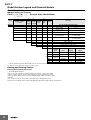
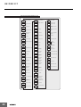
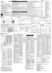
Some parameters may not be displayed depending on the model and other settings.
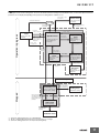
Starting in manual mode
Monitor/Setting Item Level
25
PF Monitor/
Power ON
Manual Control Level
25 Setting Item
0
S
PF Monitor/Setting
Item display 2 to 5
display 1
* The monitor/setting items to display are set in the Monitor/Setting Item 1 to 5 parameters
(Advanced Function Setting Level).
PV/Manual MV
50.0
Press S Key.*2
Press S Key.*2
Press O or S
Key for at least
1 s.*1
Press O Key for
at least 3 s while
a-m is displayed.
Press S
Key for at
least 1 s.*1
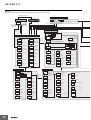
Program Setting Level
U
Operation Level
d.prg
01
25
0
prgt
Process
Value/Set Point 1
0.00
M
Elapsed
Program Time
Monitor
M
25
0
rptm
Process
Value/Set Point 2
0.00
ct1
Auto/Manual Switch
0.0
lcr1
r-r
rst
Hold
o
0.0
M
Segment Number
c-o
0
0.0
Remaining
Standby Time
Monitor
v-m
0.0
d.pid
U
M
1.i
233
PID 1 Integral
Time
40
1.c-p
8.0
233
40
M
18
al1l
PID 1 Integral
Time (Cooling)
Press O
Key for less
than 1 s.
0.0
PID 1 Dead
Band
1.ofr
1.olh
Alarm
Lower Limit
1 to 4
1.oll
0.0
1.aut
1320
1.lba
0
M
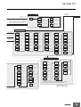
Adjustment Level
Display
Displayed only once
when entering
Adjustment Level.
AT Execute/Cancel
M
cmwt
67
D
M
styp
Segment n Format
on1
0.00
sp
Segment n SP
0
pr
Segment n Slope
0
Time Signal 1 to 2
ON Time
M
of1
M
M
Time Signal 1 to 2
Set Segment
Time Signal 1 to 2
OFF Time
M
time
Segment n Time
0.00
M
Press O Key for less than 1 s.
lcr1
0.0
Leakage Current 1 to 2
Value Monitor
1.000
M
wt-b
Wait Band
0
M
c-p
Proportional Band (Cooling)
8.0
c-i
Integral Time (Cooling)
233
M
Standby Time
c-d
Derivative Time (Cooling)
40
0.00
psps
Derivative Time
M
M
M
Heater Burnout
Detection 1 to 2
d
M
PV Input Slope
Coefficient
M
stb
Integral Time
40
off
Heater Current 1 to 2
Value Monitor
i
M
PV Input Shift
M
Fixed SP
M
0.0
inrt
Proportional Band
233
M
SP Mode
M
hb1
ins
p
8.0
M
HS Alarm 1 to 2
0.0
M
fsp
hs1
M
Communications
Writing
M
spmd
0.0
PID 1 LBA
Detection
Time
0
50.0
off
ct1
PID 1 Automatic
Selection Range
Upper Limit
ts1s
M
at
0
PID 1 MV Lower
Limit
Program
Link
Destination
end
M
psp
PID 1 MV Upper
Limit
link
M
Alarm
Upper Limit
1 to 4
45
ramp
Adjustment Level
off
PID 1 Manual
Reset Value
0
3
12
M
M
1.cdb
Program
Repetitions
0.00
1234
M
PID 1
Derivative Time
(Cooling)
Alarm Value
1 to 4
M
Valve Opening
Monitor
rpt
M
M
0
M
M
1.c-d
al1h
MV Monitor
(Cooling)
M
M
1.c-i
0
l.adj
100.0
PID 1
Proportional
Band (Cooling)
PID Set No.
M
0
M
M
For 0 to 7
al-1
Display PID
Selection
s0.0
PID 1
Derivative Time
M
M
MV Monitor
(Heating)
0
D
1
Run/Reset
(of the program)
M
M
1.d
For end
pid
M
PID 1
Proportional
Band
d.seg
end
Leakage Current 1
to 2 Value Monitor
Press O Key for less than 1 s.
1 2
3 4
5 6
7 8
D
8.0
U
M
PID Setting Level
Press the U Key
for at least 1 s in
Program SP Mode.
Display Segment Selection
END or 0 to Number of segments used − 1
d.seg
M
M
1.p
Number of
Segments Used
Process Value/Set
Point 1 or Process
Value/Set Point 2 in
Operation Level
U
Heater Current 1 to
2 Value Monitor
M
M
0.00
8
M
off
stbm
0
M
M
Program Number
0
seg
s-no
0.0
M
hold
25
D
M
M
Program No. Monitor/
Segment No. Monitor
M
prg
Display Program
Selection
M
M
pgsg
7
0
M
a-m
Program Execution
Repetitions Monitor
Press O
Key for
less than
1 s.
23
6
45
Program SP Shift Value
c-db
0.0
M
Dead Band