1
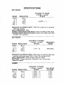
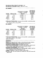
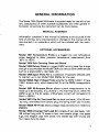
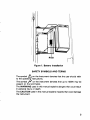
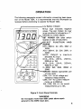
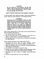
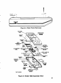
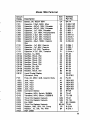
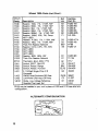
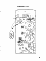
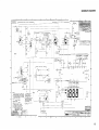
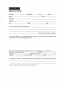
APPLICATIONS DEPT.
mmm
Model 130A/131
28775 AURORA ROAD
CLEVELAND, OHIO 44139 U.S.A.
1216) 248-0400
Publication Date: June 1984
Document Number: 130A-901-01C
WARRANTY
Keithley Instruments, Inc. warrants this product to be free from defects in
material and workmanship for a period of two years from date of shipment. During the warranty period, we will, at our option, either repair or
replace any product that proves to be defective.
To exercise this warranty, write or call your local Keithley representative,
or contact Keithley headquarters in Cleveland, Ohio. You will be given
prompt assistance and return instructions. Send the instrument,
transportation prepaid, to the indicated service facility. Repairs will be
made and the instrument returned, transportation prepaid. Repaired
products are warranted for the balance of the original warranty period, or
at least 90 days.
LIMITATION OF WARRANTY
This warranty does not apply to defects resulting from unauthorized
modification or misuse of any product or part. This warranty also does
not apply to fuses, batteries, or damage from battery leakage.
This warranty is in lieu of all other warranties, expressed or implied, including any implied warranty of merchantability or fitness for a particular
use. Keithley Instruments, Inc. shall not be liable for any indirect, special
or consequential damages.
STATEMENT OF CALIBRATION
This instrument has been inspected and tested in accordance with
specifications published by Keithley Instruments, Inc.
The accuracy and calibration of this instrument are traceable to the
National Bureau of Standards through equipment which is calibrated at
planned intervals by comparison to certified standards maintained in the
Laboratories of Keithley Instruments, Inc.
S PECIFICAT10 NS
DC VOLTS
ACCURACY (2 YEARS)
+(%rdg
counts)
1E0-2E0C
+
RANGE
RESOLUTION
200mV
2 v
100 pv
1mV
10mV
100mV
1 v
20
200
1000
v
v
v
+(0.25%
+
11
M A X I M U M ALLOWABLE INPUT: 1OOOV DC or peak AC non-switched,
750V peak switched.
INPUT RESISTANCE: 10MR.
NORMAL MODE REJECTION RATIO: Greater than 46dB at 50Hz, 60Hz.
C O M M O N MODE REJECTION RATIO: Greater than lOOdB at DC, 50Hz
and 6OHz (1kQ unbalance].
AC VOLTS
ACCURACY (2 YEARS)"
f (Yordg
counts)
1Eo-28OC
+
RANGE
200mV
2 v
20 v
200 v
750 V
RESOLUTION
100 pv
1mV
10mV
100mV
1 v
+(l%
+
31
FREQUENCY
RANGE
45Hz-500Hz
M A X I M U M ALLOWABLE INPUT: lOOOV peak non-switched, 750V peak
switched: continuous except 200mV range: 15s max above 300V.
INPUT IMPEDANCE: 10MQ shunted by less than 1OOpF.
RESPONSE: Average responding, calibrated in rms of a sine wave.
*Above 10 counts.
OHMS
ACCURACY (2 YEARS)
fWrdg
counts)
1Eo-2E0C
i(O.5%
4)
(0.2% + 11
f (0.2%
1)
f (0.2%
1)
+ ( 2 % + 11
+
RANGE
200 n
2 kQ
20 k n
200 k f l
20MR
RESOLUTION
lOOmn
1 n
10 n
100 n
10 k f l
*
+
+
+
FULL SCALE
VOLTAGE
< 0.5V
< 0.5V
> 0.7V
> 0.7V
> 0.7V
M A X I M U M OPEN CIRCUIT VOLTAGE: 1.5V.
M A X I M U M ALLOWABLE INPUT: 300V DC or rrns.
DC AMPS
RANGE
RESOLUTION
2rnA
20rnA
200rnA
2000rnA
10 A
1 PA
10 pA
100pA
1rnA
10rnA
ACCURACY (2 YEARS)
k(%rdg + counts)
18"-28'C
*(0.75%
+(0.75%
:(0.75%
*(2%
*(2%
+
+
+
+
+
1)
1)
1)
1)
1)
MAXIMUM
FULL SCALE
VOLTAGE
BURDEN
0.25V
0.25V
0.25V
0.7 V
0.3 V
OVERLOAD PROTECTION: rnA input: 2A fuse (250V), externally accessible; 10A input: 20A for 15s unfused.
AC AMPS
RANGE
RESOLUTION
2rnA
20mA
200rnA
2000rnA
10 A
1 PA
10 pA
100pA
1rnA
10rnA
ACCURACY (2 YEARS)'
*(%rdg + counts)
18O-28'C
(45HZ-500H~)
*(2%
*(2%
f(2%
+(3%
+(3%
+ 2)
+ 2)
+ 2)
+ 5)
+ 5)
MAXIMUM
FULL SCALE
VOLTAGE
BURDEN
0.25V
0.25V
0.25V
0.7 V
0.3 V
OVERLOAD PROTECTION: rnA input: 2A fuse (250V), externally accessible; 10A input 20A for 15s unfused.
*Above 10 counts.
GENERAL
DISPLAY: 3 % digit LCD, 0.6' height, with polarity and range indication.
OVERRANGE INDICATION: 3 least significant digits blanked.
MAXIMUM COMMON MODE VOLTAGE: 500V peak.
OPERATING ENVIRONMENT: Oo to 5OOC; less than 80% relative humidity up to 35OC, linearly derate 3% RH/OC from 35OC to 5OOC.
STORAGE ENVIRONMENT: -35OC to 6OOC.
TEMPERATURE COEFFICIENT: (Oo t o 18% and 28O t o 50°C): Less than
0.1 x applicable accuracy specification per OC.
POWER: 9V alkaline or carbon-zinc battery (NEDA 1604).
BAlTERY LIFE: 100 hours typical with carbon-zinc cells, 200 hours with
alkaline cells.
BAlTERY INDICATOR: Diplay indicates BAT when less than 10% of life
remains.
DIMENSIONS, WEIGHT: 178mm long x 78mm wide x 42mm thick (7.0'
x 3.1" x 1.6')).Net weigth 283gm (10 0 2 . ) .
ACCESSORIES SUPPLIED: Batten/, test leads and operating instructions.
TABLE OF CONTENTS
General Information
ManualAddenda . . . . . . . . . . . . . . . . . . . . . . . . . . . . . . . . . . . . . . . . .
1
Optional Accessories . . . . . . . . . . . . . . . . . . . . . . . . . . . . . . .
Preparation for Use . . . . . . . . . . . . . . . . . . . . . . . . . . . . . . . . .
Battery Installation/Replacement . . . . . . . . . . . . . . .
Safety Symbols and Terms . . . . . . . . . . . . . . . . . . . .
Safety Precautions . . . . . . . . . . . . . . . . . . . . . . . . . . . . . . . . . . . . . . .
4
Operation
Safety Precautions for High Energy Circuits . . . . . . . . . . . . . . . . . 6
Servicing Information
Dissassembly Instruction . . . . . . . . . . . . . . . . . . . . . . . . . . . . . . . . . .
8
Calibration . . . . . . . . . . . . . . . . . . . . . . . . . . . . . . . . . . . . . . . . . . . . .
10
Calibration Procedure . . . . . . . . . . . . . . . . . .
. . . . . . . . . . . . . 10
PartsList . . . . . . . . . . . . . . . . . . . . . . . . . . . . . . . . . . . . . . . . . . . . . .
11
GENERAL INFORMATION
The Model 130A Digital Multimeter is supplied ready for use with a battery. Descriptions of other available accessories, and other general information concerning the instrument can be found below.
MANUAL ADDENDA
Information contained in this manual is believed to be accurate at the
time of printing. Any improvements or changes to this manual will be
documented in an addendum which will be included with the, instrument.
OPTIONAL ACCESSORIES
Model 1301 Temperature Probe is a rugged low cost temperature
probe designed to allow precision temperature measurement from
-55OC to 150OC.
Model 1304 Soft Carrying Case and Stand
Model 1306 Deluxe Case is a rugged DMM carrying case that is large
enough to accomodate the Model 130A plus various other DMM articles
such as a spare battery, test leads, etc.
Model 1309 Spare Parts Kit is a collection of specially selected parts
to maintain up to ten Model 130A DMMs for one year.
Model 1600A High Voltage Probe extends the DMM to 40kV. It has a
1OOO:l division ratio, which means that 1V on the DMM corresponds to
1kV.
Model 1651 50-Ampere Shunt allows current measurements to be
made up to 50-amperes. It is a 0.0010 1% Cterminal shunt. When the
DMM is set to the 2V range, a 50-ampere current will correspond to
50mV (.0500V).
Model 1681 Clip-On Test Lead Set contains two leads, 1.2m(48 inches) long, terminated with banana plug and spring action clip-on probe.
Model 1682A RF Probe allows voltage measurements from 100kHz to
250MHz.
Model 1683 Universal Test Lead Kit consists of two test leads, 1.2177
(48 inches) long with 12 screw-in tips, two banana plugs, two spade
lugs, two alligator clips with boots, two needle tips with chucks and
four heavy-duty tip plugs.
1
Model 1685 Clamp-On AC Current Probe measures AC current by
clamping onto a single conductor. Interruption of the current path is unnecessary. The Model 1685 detects current by sensing magnetic field
produced by current.
Model 1691 General Purpose Test Lead Set consists of two .91m (36
inches) test leads with probe tips terminated in banana plugs.
PREPARATION FOR USE
Carefully unpack the Model 130A from its shipping carton and inspect
for any obvious signs of physical damage. Report any damage to the
shipping agent a t once. The following items are included with every
Model 130A shipment.
1. Model 130A DMM
2. Model 130A Instruction Manual
3. 9V Battery NEDA 1604
4. Test Leads
5. Accessories as ordered.
BATTERY INSTALLATION/REPLACEMENT
The battery is accessible from the bottom of the instrument. Note the
precautions on the case before installing or replacing the battery.
WARNING
Turn the Model 130A off and disconnect test
leads before replacing the battery. Put the cover
back into place on the compartment before
resuming use of the instrument.
A 9V battery is supplied with the instrument but not installed. To install
or replace the battery, remove the cover from the battery compartment
by sliding it off in the direction of the arrow located on the battery
cover. The battery connector snaps on and off the terminal of the battery. Improper installation of the battery will cause the connecting wires
to be severed by excess strain. Proper installation requires that the battery be positioned in such a manner (see drawing) that the leads protruding from the boot of the battery connector face toward the outside
of the battery compartment. If the instrument is going to be stored for a
long period of time or in a high temperature environment, remove the
battery to prevent leakage damage.
2
R103
Figure 1. Battery Installation
SAFETY SYMBOLS AND TERMS
A
The symbol
on the instrument denotes that the user should refer
to the operating instructions.
The symbol
on the instrument denotes that up to lOOOV may be
present on the terminal(s).
The WARNING used in this manual explains dangers that could result
in personal injury or death.
The CAUTION used in this manual explains hazards that could damage
the instrument.
r/
3
SAFETY PRECAUTIONS
The following safety precautions should be observed before operating
the Model 130A DMM.
1 . This instrument is intended for use by qualified personnel who
recognize shock hazards and are familiar with the safety precautions
required to avoid possible injury. Read over the manual carefully
before operating this instrument.
2. Exercise extreme caution when a shock hazard is present at the instrument's input. The American National Standards Institute (ANSI)
states that a shock hazard exists when voltage levels greater than
30V rms or 42.4V peak are present. A good safety practice is to expect that a hazardous voltage is present in any unknown circuit
before measuring.
3. Inspect the test leads for possible wear, cracks or breaks before each
use. If any defects are found, replace with test leads that have the
same measure of safety as those supplied with the instrument.
4. For optimum safety do not touch the test leads or the instrument
while power is applied to the circuit under test. Turn the power off
and discharge all capacitors, before connecting or disconnecting the
instrument.
5. Do not touch any objects which could provide a current path to the
common side of the circuit under test or power line (earth) ground.
Always make measurements with dry hands while standing on a dry,
insulated surface, capable of withstanding the voltage being
measured.
6. Exercise extreme safety when testing high energy power circuits (AC
line of mains, etc.). Refer to the operation section.
7. Do not exceed the instrument's maximum allowable input as defined
in the specifications and operation section.
4
OPERATION
The following paragraphs contain information concerning basic operation of the Model 130A. It is recommended that this information be
reviewed before attempting to operate the Model 130A.
Low Battery Indicator
Minus sign indicates negative
values. Plus sign implied. An over
range condition is indicated by a “1“
followed by a blank display.
S
‘ ET
POWER ON (slide switch
located on side of instrument).
ELECT F U N C T I O N A N D
RANGE
DCV-20OmV, 2V, 20V, 200V or
1ooov
ACV-200mV, 2V, 20V, 200V, or
1ooov
NOTE: 750VAC is maximum
allowable AC input.
D C A -2 m A,
20mA, 200mA,
2000mA or 10A
ACA-2mA,
20mA, 200mA,
2000mA or 10A
0-2003, 2k0, 20k0, 200kR or
20M0
-INPUTS-Selects
appropriate pair
of input jacks.
COM, V-0-for all voltage and
resistance measurements.
COM, mA-for current measurements up to 2000mA.
10A, COM, 10A, HI-for current
measurements up to 10A.
fl
Figure 2. Front Panel Controls
WARNING
Do not apply more than 500V peak above earth
ground t o the COM input jack.
5
CAUTION
Do not under any circumstance, use the 10A
COM or 10A HI input jacks with the COM input
jack for making measurements. This is a short
and will damage the instrument.
SAFETY PRECAUTIONS FOR HIGH ENERGY CIRCUITS
To optimize safety when measuring voltage in high energy distribution
circuits, read and use the directions in the following warning.
WARNING
Dangerous arcs of an explosive nature in a high
energy circuit can cause severe personal injury or
death. If the meter is connected t o a high energy
circuit, when set t o a current range, l o w
resistance range or any other l o w impedance
range, the circuit is virtually shorted. Dangerous
arcing can result even when the meter is set t o a
voltage range if the minimum safety spacing is
reduced.
When making measurements in high energy circuits use test leads that
meet the following requirements:
1. Test leads should be fully insulated.
2. Only use test leads than can be connected to the circuit (e.g.
alligator or spade plugs) for a hands-off measurement.
3. Use test leads that do not reduce the arc protection by decreasing
the voltage spacing.
Use the following sequence when testing power circuits:
1. De-energize the circuit using the regular installed connectdisconnect device such as the circuit breaker, main switch, etc.
2. Attach the test leads to the circuit under test. Use appropriate safety
rated leads for this application.
3. Set the DMM to thg proper function and range.
4. Energize the circuit using the installed connect-disconnect device
and make measurements without disconnecting the DMM.
5. De-energize the circuit using the installed connect-disconnect
device.
6. Disconnct the test leads from the circuit under test.
6
SERVICING INFORMATION
This section contains servicing information for the Model 130A.
WARNING
All service information is intended for qualified
electronic maintenance personnel only.
FUSE CHECK
With the instrument set to the 2kQ range, connect a jumper from the
V-Q jack to the mA jack. The display should read approximately .loo.
An overrange display would typically indicate a blown fuse. A display
reading other than approximately .lo0 could indicate a defective current
input circuit (seeschematic).
FUSE REPLACEMENT
A 2-amp fuse protects the 2mA through 2000mA current ranges. To
gain access to the fuse, remove the fuse Compartment cover in the
same manner as removing the battery compartment cover.
WARNING
Turn off the Model 130A and disconnect the test
leads before replacing the fuse. Reinstall fuse
compartment cover before attempting to
operate the instrument.
Remove the fuse by pulling outward on the plastic tab that encircles the
fuse body. Install the plastic tab on the new fuse and snap the fuse back
into the fuse holder. Do not replace the fuse with a higher rated value or
instrument damage that is not covered by the warranty may occur.
DIODE TEST
The 20kQ range can be used for testing of semiconductor junctions. A
junction is probably good if the Model 130A indicates an overrange
reading when the semiconductor is reversed biased, and an on-range
reading, when the semiconductor is forward biased. (The V-fl jack is
positive).
7
DISASSEMBLY INSTRUCTIONS
Place the unit face down on a bench or other similar surface and remove
the battery compartment cover. Disconnect and remove the battery.
Remove the two #4-40 X 7/8 retaining screws.
Grasp the bottom cover at the input jack end and with a lifting and forward pushing motion (see drawing), carefully remove the bottom cover.
While removing the cover, feed the battery connector through the access hole in the bottom of the battery compartment.
The component side of the PC board is now exposed and the battery
can be reconnectedfor troubleshooting. To read the display, some light
downward pressure at the top of the circuit board may be required in
order to make contact through the elastomer contact strip between the
circuit board and the LCD.
The PC board and LCD assembly are not secured once the case retaining screws are removed. Be careful not to allow the PC board and LCD
assembly to fall out or shift out of position during calibration.
To remove the PC board from the top cover, grasp the function switch
assembly and lift until the input jacks become disengaged from the
cover. The PC board can now be removed using a slight clockwise motion to free the two switch knobs from their normal positions in the
case.
The LCD assembly will remain in the top cover when the PC board is
removed. Again, be careful not to allow the LCD assembly to fall out accidentally.
The two switch knobs and bushings can be removed from the PC board
assembly by simply pulling them off the switch shafts.
The LCD assembly, along with the zebra strip connector, lifts out of the
case.
To reassemble the Model 130A, remove the cover on the fuse cornpartment (to position fuse pulling tab) and reverse the above procedures.
Be sure to replace the on-off switch cover. Common-mode voltage will
be present on the switch, creating a possible hazard if the cover is not
replaced.
8
1
t
! LIFT
PUSH
FORWARD
c--
,
I
I
I
I
I
Figure 3. Rear Panel Removal
TOP CASE
Figure 4. Model 130A Exploded View
9
CALI BRATION
Calibration should be performed every two years or whenever the instrument is known to be out of specification. Calibration should be done
at an ambient temperature of 23O f3OC ( 7 7 O f5OF), with a relative
humidity of less than 80%.
Equipment Needed:
or better.
+ 190mV DC voltage source with -05% accuracy
Model 130A Settings: DCV function, 200mV range, V-s2 and COM input
jacks.
CALIBRATION PROCEDURE
Remove the battery cover to gain access to the calibration pot R103 (see
Figure 1). Apply the 190mV to the Model 130A input and adjust R103
for a display reading of 190.0 f 1 digit. This is the only adjustment needed to calibrate the instrument. Calibration should be performed every
two years.
+
10
Model 130A Parts List
Circuit
Deslg.
BT101
c101
c102
C103
C104
C105
C106
C107
C108
c109
c110
c111
c112
C113
CR101
CR102
CR103
CR104
CR105
CR106
CR107
CR108
CR109
DS101
F101
J1001
J1002
J1003
J1004
J1005
J1006
Q101
Q102
R101
R102
R103
R104
R105
R106
R107
Sch
Description
Battery, 9V, NEDA 1604
Capacitor, 1lOpF, 500V, Mica
Capacitor, .047pF, lOOV, Polyester
Capacitor, .047pF, lOOV, Polyester
Capacitor, .IFF, lOOV, Polyester
Capacitor, .lpF, 16OV, Polypropylene
Capacitor, 1.5pF, 20V, Tantalum
Capacitor, 4.7pF, 20V, Tantalum
Capacitor, 1.5pF, 20V, Tantalum
Capacitor, .02pF, lOOOV, Ceramic
Disc
Capacitor, .IFF, 50V, Ceramic
Capacitor, .1pF, 50V, Ceramic
Capacitor, lpF, 20V, Tantalum
Capacitor, 4.7pF, 20V, Tantalum
Rectifier, l A , 800V
Rectifier, 75mA, 75V
Rectifier, 75mA, 75V
Rectifier, 75mA, 75V
Rectifier, 75mA, 75V
Rectifier, 75mA, 75V
Rectifier, 3A, 50V
Rectifier, 3A, 50V
Rectifier, 75mA, 75V
Liquid Crystal Display
Connector, Strip
Fuse, 2A,250V, 3AB, Ceramic Body
Jack, Input
Jack, Input
Jack, Input
Jack, Input
Jack, Input
Connector Battery
Transistor, NPN, Switch, 2N3904
Transistor, NPN, Silicon, GES5818
Thick Film Resistor Network
Thick Film Resistor Network
Pot, 500Q
Thick Film Resistor Network
Resistor, lMQ, lo%, lW, Comp
Resistor, .lo, .5%, lW, WW
NOT USFD
Keithley
LOC
Pert No.
-
c4
H3
F3
E4
G3
G3
04
D2
D4
c2
c2
D2
D2
F1
c4
C6
c2
c2
D2
D2
A4
84
83
G5
A4
A1
A4
A4
85
85
c4
E5
E3
SEV
SEV
G2
B3,B4
E4
84
BA-14
C-320-11OP
C-308.047
C-305,047
C-305.1
C-306.1
C-3141.5
C-314-4.7
C-314-1.5
C-316.02
C-238.1
C-238.1
C-3251
C-3194. I
R F-38
RF-28
RF-28
RF-28
RF-28
RF-28
RF-34
RF-34
RF-28
DD-27
CS-3762
FU-62
130A-303
130A-303
13OA-303
130A-303
130A-303
BH-29
TG-47
TG-138
TF-97
TF-119
RP-119-500
TF-94
R-2-1M
R-279.1
11
Model 130A Parts List (Cont.)
~~
Circuit
Desig.
R108
R109
R110
R111
R112"
R113
R114
R115
R116
R117
R118
R119
R120
R121
R122"
R123"
4T101
s101
s102
S103
u101
u102
U103
VRlOl
~~
Sch
lescription
aesistor, 1000, .1%, 1/1OW, MtF
Resistor, 9000, . l % , l/lOW, MtF
Resistor, 9k0, ,l%, 1/1OW, MtF
Resistor, 90k0, . l % , l/lOW, MtF
Resistor, 900k0, .l%, 1/1OW, MtF
Resistor, 100k0, lo%, lW, Comp
NOT USED
Resistor, 4.72k0, .l%, 1/1OW, MtF
Resistor, 10k0, , l % , l/lOW, MtF
Thick Film Resistor Network
Resistor, 0.010, 0.5%, lW, WW
NOT USED
NOT USED
NOT USED
Resistor, 9M0, .08%, 2W
Thick Film Resistor Network
Thermistor, 8mA, 500V, PTC
Switch, SPDT, ON-OFF
Switch, Rotary, Range
Switch, Rotary, Function
3 1/2-Digit Single Chip A/D
Converter
CMOS Quad Exclusive OR Gate
Low-Power JFet-Input OP-Amp
Diode, Low Voltage Reference
Supplied Test Lead Set
Keithley
Part No.
LOC
R-283-100
83
82
B2
82
82
c1
R-283-900
R-283-9k
R-283-90k
R-283-900k
R-2-1OOk
D3
02
S EV
B5
R-283-4.71k
R-283-10k
TF-96
R-280-.01
81
B1
R-281-9M
TF-104
E2
c4
S EV
E2, F2
G4
RT-7
SW-417
SW-432
sw-433
32440
F5, F6
c2
G1
30847
IC-227
DZ-62
CA-8
~
"R123 may be installed in your unit in place of R122 and R1
configuration).
ALTERNATE CONFIGURATION
12
(see alternate
COMPONENT LAYOUT
13
SCHEMATIC DIAGRAM
$'"
INPUT
I
I
15
SERVICE FORM
M o del No.
Serial No.
~
Name
P.O. No.
date
Phone
Company
Address
City
State
Zip
List all control settings and describe problem.
(Attach additional sheets as necessary.1
Show a block diagram of your measurement system including all instruments connected (whether power
is turned on or notl. Also describe signal source.
Where is the measurement being performed? (factory, controlled laboratory, out-of-doors, etc.1What power line voltage is used?
Variation?
Frequency?
Ambient Temperature?
Variation?
O F . Rel. Humidity?
Other?
OF.
Any additional information (If special modifications have been made by the user, please describe below 1
‘Be sure t o Include your name and phone number an this sewice form
Keithlsy Instruments. lnc./28775 Aurora RoadiCleveiand, Ohio 44139/U.S.A./(2161 2484400/Teiex: 985469
WEST GERMANY: Keithlsy Inatruments GmbH/Heiglhofstrasse 5/D-8000 Munchen 70/314 289/Telex: 1345000
GREAT BRITAIN: Keithlsy Instrurnenta. Ltd./l, Boulton RoadiReading, Berkshire RG2 ONL110734) 88 12 87/Telex: 847047
FRANCE: Keithlsy Instruments SARL/2 Bis, Rue LBon Blum/B.P. 60/91121 Palaiseau Cedexll61 0115 155/Telex: 600933
NETHERLANDS: Keithley lnatrumentr BV/Arkelsedijk 4/NL4206 AC Gorinchem/(01830l 25577/Telex: 24 684
SWITZERLAND: Keithlsy Inatruments SAIKriesbachstr. 4/CH-8660 DubendorfiOl 821 94 44/Telex: 57 536
AUSTRIA: Keithley Instruments Gss.m.b.H/Doblinger Hauptstr. 32/A-1190 Wien/0222 314 289/Telex: 134500