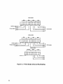
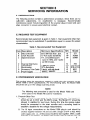
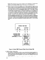
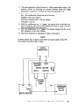
1
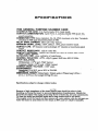
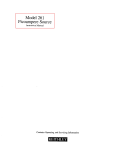
Model 7056
General PurposeScannerCard
Instruction
Contains
Operating
and
Servicing
Information
Document
Number:
Manual
7056-901-01
Rev. D
WARRANTY
Keithley
Instruments,
workmanship
Keithley
Instruments,
shipment:
During
Inc. warranty
this product
to be free from defects in tnatcrial
and
for a period of I year from date of shipment.
Inc. warrants
the following
probes, cables, rechargeable
the warranty
items for 90 days from
the date of
batteries, diskettes, and documentation.
period, we will, at our option, either repair or replace any product
that proves to be defective.
To exercise
Keithley
return
this warranty,
headquarters
instructions.
facility.
write
or call your local Keithley
in Cleveland,
Ohio. You will
Send the product,
representative,
be given prompt
transportation
prepaid,
to the indicated
Repairs will be made and the product returned, transportation
or replaced products are warranted
or contact
assistance and
for the balance of the original
service
prepaid. Repaired
warranty
period, or at
least 90 days.
LIMITATION OF WARRANTY
This warranty
Keitbley’s
does not apply to defects resulting
express written
does not apply to fuses, software, non-rechargeable
age, or problems
OR FITNESS
SHALL
MENTS
OF ALL
KEITHLEY
BE LIABLE
AND
SUCH EXCLUDED
without
DAMAGES
DAMAGES
COSTS OF REMOVAL
AND
RESULT OF INJURY TO ANY
INC.
NOR
INDIRECT,
OUT
IF KBITHLEY
OF THE
SHALL
OR
PROVIDED
HEREIN
REMEDIES,
ARISING
EVEN
IN ADVANCE
EXPRESSED
OF MERCHANTABILITY
USE. THE REMEDIES
DIRECT,
also
instructions.
WARRANTIES,
WARRANTY
INSTRUMENTS,
FOR ANY
SOFTWARE
ADVISED
OTHER
IMPLIED
SOLE AND EXCLUSIVE
CONSEQUENTIAL
BEEN
ANY
FOR A PARTICULAR
ARE BUYER’S
NEITHER
IS IN LIEU
INCLUDING
modification
batteries, damage from battery leak-
arising from normal wear or failure to follow
THIS WARRANTY
IMPLIED,
from product
consent, or misuse of any product or part. This warranty
ANY
OF THE
INCIDENTAL
OR
USE OF ITS INSTRU-
INSTRUMENTS,
POSSIBILITY
INCLUDE,
OF ITS EMPLOYEES
SPECIAL,
OF SUCH
INC.,
BUT ARE NOT LIMITED
INSTALLATION,
LOSSES SUSTAINED
PERSON, OR DAMAGE
TO PROPERTY.
HAS
DAMAGES.
TO:
AS THE
Model 7056
General Purpose Scanner Card
Instruction Manual
01992,
Kcithlcy
Instruments,
Inc.
All rights reserved.
Cleveland,
January
Document
Ohio,
1992,
Number:
U.S.A.
First Printing
7056-901-01
Ilcv. D
Safety Precautions
The following
safety precautioos
ciated instrumcntatioo.
with nowhazardous
should be obsewed before using this product and any asno-
Although
some inrtromeots
This product is intended for use by qualified
familiar
with tbc safety pnxaotions
formation
and accessories woold nonnally
bo used
voltages, there arc situations wberc hazardous conditions may be present.
carefully
personnel who rccogoiu:
rcqoircd
shock hazards and are
to avoid possible injuly. Read lbe operating
it]-
before using the product.
‘The types of product users arc:
Kesponsiblc
body
equipment,
is tbe iodividunl
or group responsible
for ensuring tlnt the equipment
for the USCsod owinleoaoce
ia operated within
ing limits, and for ensuring that operators are adequately
Operators
use the product for its intended function.
its spccilications
of
and operat-
trained.
Tbey most be trained in electrical safety
procedures and proper use of the iostrument. ‘lhey most be protected from electric shock and
~onmt
with hazardous live circuits.
Maintenance
personnel
perform mutioe procedures oo the product to keep it operadog, for
example, setting the hoc voltage or replacing consumable materials. Maintenance
am dcacribed in the manual. The procedures explicitly
Othcrwisc,
they should be performed
Service personnel
proccdurcs
state if the operator ~nay perform them.
only by senice pcnonoel.
are trained to work on live circuits, sod perfoonn safe installations
pairs of products. Ooly properly
trained setvice personocl may perform
installation
sod reand scr-
vice procedures.
Exercise extreme caution whco a shock hazard is present. Lethal voltage may be present on
cable coonector jacks or test fixtures.
111~ American
National
Standards lostitute
(ANSI)
stam that a shock hazard exists wheo voltage levels greater than 30V RMS, 42.4V peak, or
60VDC
are present. A good safety practice
in any unknown
circuit
is to expect that hazardous
voltage is present
before measuring.
Users of this product must be protected fmm electric shock at all timer. The responsible body
must eosum thtat wets aw pwented
a.cce~saod/orinsulatcd
from every connection point. lo some
cases, conoectiuns most be exposed to potential buman cootact. Product usa
io these circuo-
stances must be trained to protect themselves from the risk of electric shock. If the circuit is capable of operating at or abovc 1wO volts, no conductive
AY described in the Ioteroational
ital multimcter
Electratechnical
measuring circuits (e.g., Keifhley
2010) are Installation
part of the circuit may be exposed.
Commission
Models
Category II. All other instruments
(IEC) Standard IEC 664, dig-
175A, 199, 2OOQ,2COl, 2002, and
signal tennioals
are Installation
Cat-
egory I and must oat be conoected to mains.
Do not conoect switching
cards directly
to unlimited
used with impedance limited sources. NEVER
Wheo conoccting
sources to switching
power circuits. They are inlendcd to bc
connect switching
cards. iostall protective
cards directly
to AC mains.
devices to limit fault current
sod voltage to tbc card.
Before operating ao instrument,
make sure the line cord is connected to a properly grounded
power receptacle. Inspect the connecting
cables, test leads, and jumpers
for possible wear,
cracks, or breaks bcforc each oso.
For maximum
safety, do not touch the product, test cables, or any other instrumcots while pow-
er is applied to the circuit under test. ALWAYS
dischuge
soy capxitors
remove power from the entire test system sod
before: coooccting or disconnecting
cables or jumpers, installing 01
removing switching cards. or making iotemtil chaogcs, socb as installing or nzmoviog jumpers.
Vu not touch soy object that could provide a con-cot path to tbc common side of the circuit
under test or power line (eatth) ground. Always
make measurements witb dry hands while
standing oo a dly, insulated surface capable of withstanding
The instrument
tbc voltage bciog measured.
and accessories most be used in accordance with its specifications
eratiog iostructioos
or tbe safety of the equipment
Do not exceed the maximum
tbe speciticationr
signal levels of the instruments
sod operatiog
panels, or switcbiog
information,
and op-
may be impaired.
and es show
and accessories. as defined in
on the instrument
or test fixture
cant.
When fores are used in a product, replace with same type sod rntiog forcootioued
pmtectioo
against fire hazard.
Cbassir connections
must only be used as shield coooectioos
for me~suriog circoits, NOT as
safety eaflh ground connections.
If you are using II test fixture, keep the lid closed while power is applied to the device under
test. Safe operation requires tbe we of a lid interlock.
1ra@
screw is present, connect it to safety earth ground uaiog the wire recommended
in
the user documentation.
The
!
symbol on an iostroment
n
stmctions located io tbc manual.
The h
indicates that the user should refer to the operating
ill-
symbol on al iostmment shows that it CNI source or IIICRIIUII: loo0 volts or more, ill-
eluding the combined etTect of normal ad common mode voltages. Use stiuldarrl safety precaulions to avoid pcrsooal cootect with these voltages.
TIE WARNING
beading in A manual enplaios dangers that might result in personal injury or
death. Always read the associated information wy carefully hcfore ptxformiog the indicated
pC"CCdU~C.
The CAUTION
beading in a manual explains
hazards that could damage the instrument.
Such damage may invalidate the warrmty.
lostrumcntatioo
and accessories shall not be connected to humans.
Before performing
To maintain
pmtcctioo
coils, including
Keithley
any maintenance,
disconnect the line cord and all test cables.
from electric shock and ftre, replacement
the power transfouner,
Instruments.
that are not safety r&ted
chased from other suppliers as long as they are equivalent
to tbe original
that selected parts should be purchased only through Keithley
racy sod fonctiooality
of the product.)
call a Keithlcy
To clean an instrument.
of the instrument
in mains cir-
Standard fuses, with applicable national safety appmvals, may be used
if the ratiog sod type are the same. Other components
ment component,
components
test leads, and ioput jacks, must he purchased from
Iostmmcnts
(Note
to maiotain acco-
If you we unsure about the applicability
Instruments
may hc por-
component.
of a replacc-
office for information.
use a damp cloth or mild, water based cleaner. Clean the exterior
only. Do not apply cleaner directly
enter or spill on the instrument.
tb the instrument
or allow liquids to
Products that consist of a circuit hoard with no case or cbas-
sis (e.g., data acquisition
board for installation
ing if handled according
to instructiuns.
into a computer)
should neverrequire
If the board becomes contaminated
is affected. the hoard should he returned to the factory
clean-
sod operation
for proper cleaninglserviciog.
tie”. 2rB
SPECIFICATIONS
7056 GENERAL PURPOSE SCANNER CARD
CHANNELS PER CARD: IO in 2-pole mode, 20 in I-pole mode.
CONTACT CONFIGURATION:
2- le Form A, includes Model 7055 Quick LXs~omeCt Card. HI or LO switch ecr to a eerlerete
outout
for l-m&
mode, common
.
.
.
guard connection
CONNECTOR TYFE: Screw temina,, No. 18 AWG ma.ximum wire size. Tem,i,,a,s
mounted on 7055 quick dtscok
potion of 7056.
RELAY DRIVE CURRENT: 24mA per relay typical.
MAXIMUM
SIGNALsLEVEL:
150”. 25hA,
IOV.$ peak (resistive load).
CCl,“JT
LIFE:
10 dosures (cold switching);
10 ciosores (at maximum
signal
CONTACT
RESISTANCE:
cZI2 to rated life.
CONTACT POTENTIAL:
<lC@V per contact pair input to output with copper
leads (c5OpV typical).
ACNATtON
TIME: <2ms, exclusive of mainframe.
CHANNEL
ISOLATION:
>lOgQ, OOpF typical; MdB into 500 @ I-.
INPUT ISOLATION:
Differential:
>lOgP and <50pF typical.
Common Mode: >lOgQ and 45OpF typical.
COMMON MODE VOLTAGE:
<,50”
peak.
ENVIRONMENT:
operating:
0’ to MT, up to 3sT at 70% RH.
storage -WC to WC.
DIMENSIONS, WEIGHT: 32mm high x 114mm wide x 272mm long K25 in. x
4.5 in. x 10.75 in.). Net weight 027kg (9.5 oz.).
Spedfications
subject to change without
notice.
NOTE
BecauseofhighimpedanceoftheboardsSedalcareshouldbetakeninboth
handling and using the board to prevent
egradatmn of prfomence.
Handle the
board by the edges when win
it and kee it free of body oils, dirt and contaminants.
To dean the board use distill e% water an % a dean cotton swab or soft brush
Thoroughly
saub the beard and then remove all water residue with dry nitrogen gas.
After the board is dean bake for five hours at 54°C and low relative humidity.
TABLE OF CONTENTS
1.1
1.2
1.3
SECTION
l-GENERAL
INFORMATION
Introduction
............................................
Warrann/ Information
....................................
ManualAddenda
........................................
2.1
2.2
2.3
SECTION
Z-OPERATION
lntraduction
............................................
Wiring and Installation.
...................................
Operating Considerations
.................................
3
3
5
3.1
3.2
3.3
SECTION
3--SERVICING
INFORMATION
Introduction
............................................
Required Test Equipment
.................................
Performance
Verification
..................................
7
7
7
4.1
4.2
4.3
4.4
4.5
SECTION
4-REPLACEABLE
PARTS
Introduction
............................................
ReplaceablePans
........................................
Ordering Information
.....................................
FactoryService
..........................................
Component
Layout and Schematic
Diagram
13
13
13
13
13
.................
LIST OF FIGURES
1
2
3
4
5
6
7
a
9
10
11
Typical Channel, Voltage Scanner Mode ....................
Typical2by5Matrix
....................................
Channel Numbering-l-Pole
..............................
Thermal Offset Test ......................................
Model 7056 Timing Test in Model 705. ......................
Model7056
Isolation Test in Model 705 .....................
Differential
Input Isolation .................................
Channel Isolation
........................................
.................
Model7055,
Component
Location Drawing.
.................
Model 7056, Component
Location Drawing.
..........
General Purpose Scanner Card, Schematic
Diagram
3
4
6
a
9
10
11
12
15
16
17
LIST OF TABLES
1
2
3
Recommended
Test Equipment
............................
Model 7055 Replaceable Parts List ..........................
Model 7056 Replaceable Parts List ..........................
7
14
14
SECTION 1
GENERAL INFORMATION
1.1 INTRODUCTION
The Model 7056 is e general purpose relay ecenner plug-in card which is fieldinstallable in en appropriate Kelthley ecenner mainframe (e.g. Model 706). The
Model 7056 w/II switch up to 10 channels. The card can be used 88 e voltage
ecenner. independent
relay card or e matrix card. The Z-pole switching
18 eccompllshed
in less than 2ms and the expected relay life is lo8 closure8 et the
maximum contact ratings. Barrier strips ere used to facilitate input end output
connections
to the relay ecenner plug-in card. The plug-in card can easily be
removed through the rear panel of the ecenner mainframe.
The Model 7066
provides the connection
to the individual channels via the screw clamp type
terminal strips.
1.2 WARRANTY
INFORMATION
Warranty information is staled on the inside front cover of the manual. If there is
e need for service, contact the Keithley representative or authorized repair facility
in your area. Check the back cover of this manual for addresses. The service
form supplied at the end of the manual should be used to provide the repair
facility with adequate informoiion
concerning any difficulty.
1.3 MANUAL
ADDENDUM
Improvements
or changes
cluded with this manual.
to this manual will be explained
on en addendum
in-
1
SECTION 2
OPERATION
2.1 lNTROOUCTlON
This section provides information
priate scanner mainframe.
2.2 WIRING
AND
needed to use the Model 7056 with an sppro.
INSTALLATION
1. Wiring Configuration-Each
channel on the Model 7066 card consists of 10-Z
Form A relays and 2-1 Form A relays for one pole mode. The card ten be
wired es e voltage scanner card, independent
relay card, or e matrix card.
Channel 1, on the component
designation.
shows the terminal locations
which are similar to Channels 1 through 6. Channel 10 shows the terminal
locations typical for Channels 5 through 10.
A. Voltage Scanner Card-The
Model 7056 can be used as a voltage scanner
card. Figure 1 shows e wpical channel in the voltage scenner mode. When
the Model 7056 card is used in e Model 705 scenner mainframe, one of 10
channels can be switched to the output et 8 time. When ecanning, the
relay contract8 of one channel will break before the relay confactS on e
second channel will make, ensuring isolation between channels.
B. Independent
Relay Card-The
Model 7066 plug-in card can be used es an
independent
relay card. The relay switching 18 still controlled by the scanner mainframe. When using the circuit, do not exceed the maximum contact ratings.
C. Matrix Card-The
Model 7066 ten be used 88 e 1 by 10 or a 2 by 6 matrix
card. The Model 7056 should be first set up 88 e voltage scanner card. To
use it es e 1 by 10 matrix card, the output HI or output LO can be used to
switch to any of the 10 input HIS or input LOS. For “88 88 e 2 by 6 matrix
card, refer to Figure 2. This allows the ueer to switch the output HI or output LO to sny of five inputs. Figure 2 shows the 2 by 5 matrix setup.
2. Installation-Refer
to the Model
706 Instruction
Msnual
for installsdon
structions.
TO OTHER CHANNELS
Figure
1. Typical
Chennel,
Voltage
Scanner
Mode
3
in-
LO
OUTPUT
HI
-iy2
CH.1
CHl
LO
<
CM.2
HI
r---t
“...”
rl
k-4
I
\
c
F”1
-Ii+,
(
CM.4 LO
I
\
c
F”C
i-i-c”0
(
CH.0
HI
CM5 LO
WI.7
CH7 LO
\
WI.6
F”o.
Figure
2. 2 by 6 Matrix
HI
2.3 OPERATING
CONSIDERP,TIDNS
1. Signal Levels-The
signal levels that the Model 7056 operates et are 1OV
115OV maximum~/lOmA
1250mA maximum).
The load should only be
resistive, and 1OVA is the maximum switching level with a resistive load. The
contact life of the relays with normal signal levels is l~closures.
At maximum
signal levels, the number of closures is degraded by a factor of 10.
NOTE
Reactances in the system will cause switching transient% during
switching. These transients should not exceed the ratings given.
If they do, the transients can degrade the relay contact life.
2. External Considerations-The
Model 7056 specifications
ere for a resistive
load; however, external circuit capacitances and inductances ten cow% excessive cur~%nt% and voltages across the relay contacts
The currents and
voltages must be limited to within the contact ratings.
A. Capacitance-Charged
capacitances
in the circuit
ten
cease excessive
currents isurge current4 to flow through the relay contects, if the SOWC%
is shorted out or the output is switched to capacitive loads. This excessive
current can weld the relay contacts
together.
Therefore,
use series
resistors where needed to limit the maximum current that can flow, to
within the contact ratings. For example. a DC power supply specification
mey indicate that the output
current is limited to lOmA. However,
because of internal capacitors connected across the power supply output.
high surge currents can easily flow through the relay contacts. If they are
shorted or when switched
to reactive loads lsuch as the input to %
voltmeterl.
a surge may result. The surge current can be very high and
may only be a few microseconds in duration, but they can still weld the
relay contacts together. The currents must be limited to within the contact ratings of the relay. The limits are stated in paragraph 2.3.1.
6. Inductance-The
inductance of cables can produce high voltage and arcing across the relay contacts when switching. The peak transients must be
limited to within the contact ratings. The limit% 81% stated in paragraph
2.3.1.
C. Cables-Shielded
cables should be used with the Model 7066 card when
switching above 5OV. The shield should be connected to the circuit LO or
Guard. This helps prevent excessive rod&ion
from the cables from interfering with any equipment.
0. I-Pole Configuration-The
Model 705 ten be used in the l-pole configuration by utilizing front panel program number 6 on the Model 705 mainframe. Refer to the Model 705 instruction manuel for information concerning the front panel programs. Generally, the l-pole configuration
is used
for applications where a user can use % single common ground in the
meesurement.
The channel numbering
for the l-pole configuration
ie
shown in Figure 3. The l-pole output is taken from the IP connector to
ground on the Model 7056.
Flgure 3. I-Pole
6
Mode Channel Numbering
SECTION 3
SERVICING INFORMATION
3.1 lNTROOUCTlON
The following section contains 8 performance
procedure.
Since there are no
calibration
adjustments,
no
recslibrotion
is necessary.
Recommended
maintenance would include inspection of the scanner plug-in board and card
edge connector to ensure good electrical contact.
3.2 REQUIRED TEST EQUIPMENT
Recommended
recommended
test equipment
is given in Table 1. Test equipment other than
may be substituted
if specifications
equal or exceed the stated
characteristics.
Table 1. Recommended
Minimum
Test Equipment
Specifications
Zero drifi’less than .$N.
IV Full Scale Sensitivity
TTL compatible square
wave to 10Hz. and 1 pulse
per 30 minutes.
Accessory
Triax Cable
3.3 PERFORMANCE
Triggered Sweep
lOgA Sensitivitv
Triaxial with cl(p leads.
IOVDd, 1OOVDC
II
KI
TEK
KI
!
“K;
705
7000 seril
619or61
1
%’
VERIFICATION
This section gives the procedures needed to verify that the operation of the
Model 7056 is within spocificntions.
For the following
tests, the Model 7066
should be set up in the voltago scanning mode,
NOTE
The following
test procedure is used for the Model
when used in the Model 705 scanner mainframe.
1. Thermal
7066 card
Offset Test
A. Figure 4 shows the test setup for the ttwmal offset test. The Model 177
should be set to DCV and the 2OmV range. The Model 177 should be
allowed to stabilize for two hours. During this time the analog output
should be connected
to the chart recordor and a recording made to
establish a baseline for the voltage measurements.
B The 10 input connections
on the Model 7056 plug-in card should be
shorted together between HI and LO with a length of #14 to #22 AWG
solid copper wire, i.e.. 81120 screws should be tied together. With a cable
attached to ths output, the plug-in card should then be inserted into the
7
Model 705 mainframe
cable from the Model
and power applied to the Inainfram?
Conn@ct the
7056 outfxn to the input of the Model 177.
C. After the warm.up time has elapsed and a stable baseline is visible on the
chart recorder. set the Model 705 scanner mainframe’s interval time to 16
minutes. Also set the Model 705 to the Channel mode and the Step mode.
Scan each channel at the programmed
interval rata (15 minutes). This is
accomplished
by pressing the START/STOP
button on the Model 705
nnce for each channel. Once the START/STOP
button is activated for
one channel. the Model 705 closes that channel for the programmed interval rate 115 minutes1 then opens that channel and advances to the next
channel. To scan the next channel press the START/STOP
button.
The thermal EMFs generated in each channel will be visible as a deflection
from the baseline on the recording. The maximum deflection should be no
more than f lOO,U from the baseline for any channel, exclusive of switching spikes. The ambient temperature should be kept at 23OC -t 3% for this
test.
I
MODEL 706/7066
COPPER WIRE
SHORTS ON
CHANNELS 1 TO 10
Figure 4. Model 7066 Thermal Offset Test In Model 706
2. Relay Contact Timing Test
A. The 10 input connections
and the output should be shorted together between HI and LO with short pieces of wire, on the Model 7056 card. Do
not connect each channel together; just connect the individual HI and LO
of each channel.
B. Figure 5 shows
8
the equipment
setup for this test. Select Channel
1.
C. The signal generator should be set 10 B 10Hz squorowave
output. The
scanner should be selecting the desired channel when the signal
generator’s output is a 1 and all off when the generstor is 0.
0. The oscilloscope should be set to trigger on the signal generator’s
put. The oscilloscope should be s@ as follows:
SWEEP:
out-
0.5ms per division.
VERTICAL
SENSITIVITY:
TRIGGER:
External
5V per division.
E. With the oscilloscope on I + j trigger, the typical time to the first contact la transition from 1OV to OVJ should be 0.3177~ or more. The contacts should settle in less than 2ms.
F. Turn the oscilloscope to (-1 trigger.
1OV transition is less than 0.25ms.
G. Test all 10 channels
as described
The typical
release time for a 0 to
in steps A through
F.
NOTE
A series resistor lR$l must be used with the power
The resistor should be 1ktI or larger.
supply
output
HI,
SIQNAL
QENERATOR
HI
I
LO
L
IEXTERNAL
COM
TRIQQER
MODEL 706/7066
INPUT
HI LO
; 2
OUTPUT
HI I.0
- z
1
CHANNEL
UNDER
TEST
HI
LO
TRIQQER “I
INPUT
LO
OSCILLOSCOPE
Figure
&
Ra
-
MODEL 230
“’ VOLTAGE
SUPPLY
Lo 1ov DC
5. Model 7066 Timing Test In Model 706
g
3. Isolation
Tests
Input Isolation Common Mode
A. This test measures the common
mode input isolation which
resistance between the signal lines and power line ground.
the test setup for this test.
8. Short the output HI and LO connections
a short piece of wire.
C. Set up the test circuit shown
together
is the leakage
Figure 6 shows
on the Model 7056 with
in Figure 6.
0. Insert the Model 7056 into the mainframe and sit the Model 705 to STEP
(see Model 705 Instruction Manualland
Channel 1.
E. Set the Model 230 for 1OOV DC and set the electrometer
F. Program the Model 230 output
the ZERO CHECK position.
G. Take the reading and manually
readings for each channel should
calculate the input isolation. R
capacitance
of the circuit, the
capacitance is charged up. Wait
MODEL
10
6. Model
7066
out of
scan from Channel 1 through 10.
be less than 1 x lV7A. Using Ohms
= E/I = lOOV/lO-7A
= llN1. Due to
offset current may be high until
until the reading settles out.
706,7058
OUTPUT
Figure
to lO7A range.
to operate and take the electrometer
Isolation
HI
LO
Test
In Model
706
The
Law
the
the
Input 18oletion. Differential (Guarded)
A. This test meawre~
the differential
input isolation which is the leakage
resistance between a guarded channel HI and LO. Set up the test circuit
shown in Figure 7.
l3. Set the Model 705 to Channel
230 to output
1 end the Step mode.
1OOV. set the electrometer
Program
the Model
to Amps and take it out of zero
check.
C. Take the reading on the electrometer and manually ?san from Channel 1
through 10. The reading for each channel should be less then 1 x 10⁻⁷A.
Using Ohms Law calculate the input isolation
R=Ell=lOOV/10~A
= lL%fl. Due to the capacitance of the circuit, the offset current may be
high until the capacitance is charged up. Wait until the readings settle out.
Flgure 7. Differential
Input Isolation IGuarded)
Test Set Up
Channel Isolation
A. This test measures the channel isolation which is the isolation
channels. Set up the circuit shown in Figure 8.
i3
Short
the HI and LO connections
of each channel
on the Model
between
7066.
C. Set the Model 705 to Channel 1 end the Step mode. Program the Model
230 to output 1OOV. set the electrometer to Amps end take it out of Zero
Check. Program Channel 1 es open end the other channels es closed.
D. Tako the reading on the electrometer and manually scan from Channel 1
through 10. The reading for each set of channels should be less then
lo-‘A.
Using Ohms Law calculate the channel isolation for each set of
channels. R = E/I = lOOV/lO--7A = l@a. Duo to the capacitance of the circuit the offset current may be high until the capacitance of the circuit is
chargod up. Wait until the readings settle out.
11
MODEL 706/7066
CHANNEL
UNDER
OUTPUT
HI
LO
GUARD
c%l
HI
LO
I
MODEL
230
POWER
SUPPLY
Figure 8. Channel Isolation Test Set Up
12
SECTION 4
REPLACEABLE PARTS
4.1 INTRODUCTION
This eectlon conteln~ replacement ports information,
component
layout for the Model 7056.
4.2 REPLACEABLE
e schematic
diagram and e
PARTS
Porte ore listed alpha-numerically
in order of their circuit dealgnstlon.
contains ports list information
for the Model 7056.
4.3 ORDERING
INFORMATION
To place en order, or to obtain
information
concerning
tact your Keithley representative or the factory.
dresses. When ordering include the following
1, Instrument Model Number
2. Instrument Serial Number
3. Part Description
4. Circuit Description lif applicable~
5. Keithley Part Number
4.4 FACTORY
Table 3
replacement
perte, con-
See the inside front cover for adinformation:
SERVICE
If the instrument is to be returned to the factan/ for service, please complete
service form which follows this section and return it with the instrument.
4.6 COMPONENT
LAYOUT
AND
SCHEMATIC
the
DIAGRAM
Figure 9 contains e component
layout for the Model 7065, and Figure 10 contains the component
layout for the Model 7056. A schematic diagram of the
General Purpose Scanner Cord is contained in Figure 11.
13
Table 2. Model 7055 Replaceable Paris
ClrCUit
b3ig.
Description
Keithley
Part No.
iooi
J1002
HO03
Ji 004
J1005
Handle
Rivet
Connector
Connector
Connector
Connector
Connector
FA-119
FA-121
cs-457-l
CS-457-2
cs-457-l
CS-457.2
CS-457-2
Connector, Male (mates for CS-455)
#2-56 x 706 Phillips Pan Head Screw
#2-56 Hex Nuts
Clamp Assembly, Upper
a. Clamp, Upper
b. Strip, Rubber
Clamp Assembly, Lower
a. Clamp, Lower
b. Strip Rubber
#6-32 x 5/i 6 Phillips Pan Head Screw
#6-32x 1 Phillips Pan Head SCI’eW
CS-456
PI006
7055-303-l
7055305
26621
7055-306
7055-307
26621
Table 3. Model 7056 Replaceable Parts
Circuit
Deslg.
Description
Kelthley
Part No.
Cl01
Capacitor, IOpF, 25V, Aluminum Electrolytic
C-314-10
JlOO6
Connector, Female
#B-56 y 7/16 Phillips Pan Head Screw
#2-56 Hex Nuts
cs-455
KlOlK112
Relay
RL-I 30
interconnect Board
7055
14
Figure 9. Model 7099 Component Localon
Drawing
,9
18
Figure 10. Model 7066 Component Location Drawing