1
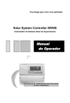
Operation manual of solar water controller SR500 -------------------------------------------------------------------------------------------------- ~0~ Operation manual of solar water controller SR500 -------------------------------------------------------------------------------------------------- Contents Contents-----------------------------------------------------------------------------------1 1. Safety information ------------------------------------------------------------------3 1.1 Installation and commissioning--------------------------------------------------3 1.2 About this manual-------------------------------------------------------------------3 1.3 Liability waiver-----------------------------------------------------------------------3 1.4 Description of symbols-------------------------------------------------------------4 2. Installation-----------------------------------------------------------------------------5 2.1 Installing the controller ------------------------------------------------------------5 2.2 Opening/closing the connectin cover of controller--------------------------5 2.3 Electrical connections--------------------------------------------------------------5 2.3.1 Preparation before connections-----------------------------------------------5 2.3.2 Terminals connection------------------------------------------------------------6 2.4 Installing electromagnetic valve-------------------------------------------------7 2.5 Faults checking of electromagnetic valve-------------------------------------8 2.6 Installation of sensor -------------------------------------------------------------9 2.7 Diagram of cable connection of water temperature and water level Sensor---------------------------------------------------------------------------------9 2.8 Anti-overflow probe installation instructions---------------------------------10 3. Introduction of solar system ---------------------------------------------------11 3.1 System diagram --------------------------------------------------------------------11 4. Button of controller and display illustration-------------------------------12 4.1 Adjust buttons------------------------------------------------------------------------12 4.2 Screen display illustration--------------------------------------------------------12 4.3 Signai illustration--------------------------------------------------------------------13 4.4 Code illustration--------------------------------------------------------------------13 5. Commissioning----------------------------------------------------------------------13 5.1 Setting the clock---------------------------------------------------------------------14 6. Functions setup and operation------------------------------------------------14 6.1 Description of auto mode function----------------------------------------------14 6.2 Temperature controlled auxiliary heating at preset three time sections ~1~ Operation manual of solar water controller SR500 -------------------------------------------------------------------------------------------------------------------------------------------------------------------------------------------------15 6.3 Thermostat water supply function----------------------------------------------17 6.4 Manual water loading function---------------------------------------------------18 6.5 Temperature controlled water-loading function----------------------------19 6.6 Water supply function when lack of water------------------------------------19 6.7 Manual heating function-----------------------------------------------------------20 6.8 Pipe insulation function------------------------------------------------------------21 6.9 Thermostat heating function----------------------------------------------------21 6.10 Collector high temperature protection--------------------------------------22 6.11 Low water pressure protection-----------------------------------------------22 6.12 Auto function----------------------------------------------------------------------23 6.13 Protection function--------------------------------------------------------------23 7. Technical data----------------------------------------------------------------------23 8. Delivery scope-------------------------------------------------------------------------24 9.Liability range of manufacturer-----------------------------------------------------24 ~2~ Operation manual of solar water controller SR500 -------------------------------------------------------------------------------------------------- 1. Safety information 1.1 Installation and commissioning When laying cables, please ensure that no damage occurs to any of the constructional fire safety measures presented in the building. The controller must not be installed in rooms where easily inflammable gas mixtures are present or may occur. The permissible environmental conditions must not be exceeded at the site of installation. Before connecting the device, make sure that the energy supply matches the specifications of controller showed on the type plate. All devices connected to the controller must conform to the technical specifications of the controller. All operations on an open regulator are only to be conducted cleared from the power supply. All safety regulations for working on the power supply are valid. Connecting and /or all operations that require opening the regulator (e.g. changing the fuse) are only to be conducted by specialists. 1.2 About this manual This manual describes the installation, function and operation of a solar thermal controller. When installing the remaining components e.g. the solar collectors, pump assemblies and the storage unit, be sure to observe the appropriate installation instructions provided by each manufacturer. Installation, electrical connection, commissioning and maintenance of the device may only be performed by trained professional personnel. The professional personnel must be familiar with this manual and follow the instructions contained herein. 1.3 Liability waiver ~3~ Operation manual of solar water controller SR500 -------------------------------------------------------------------------------------------------The manufacturer cannot monitor the compliance with these instructions or the circumstances and methods used for installation, operation, utilization and maintenance of this controller. Improper installation can cause damages to material and persons. This is the reason why we do not take over responsibility and liability for losses, damages or cost that might arise due to improper installation, operation or wrong utilization and maintenance or that occurs in some connection with the aforementioned. Moreover we do not take over liability for patent infringements or infringements – occurring in connection with the use of this controller- on third parties rights. The manufacturer preserves the right to put changes to product, technical date or installation and operation instructions without prior notice. As soon as it becomes evident that safe operation is no longer possible (e.g visible damage). Please immediate take the device out of operation. Note: ensure that the device cannot be accidentally placed into operation. 1.4 Description of symbols Safety instruction: Safety instructions in the text are marked with a warning triangle. They indicate measures, which can lead to injury of persons or safety risks. Operation steps: small triangle “►”is used to indicate operation step. Note:Contains important information on operation or function. ~4~ Operation manual of solar water controller SR500 -------------------------------------------------------------------------------------------------- 2.Installation 2.1 Installing the controller Note:the controller must only be installed in an area having an adequate level of protection. ►Choose a suitable location ►Mark the hole position of hang panel on the wall (note the right side of hang panel) ►Drill the fastening hole and insert a plastic expansion screw . ►Fix the bottom panel with screw on the drilled hole. ►Hang up the controller on the hang-panel. 2.2 Opening/closing the connection cover of controller ► Loosen the screw ① and ②, open the cover, move the cover upwards. ► Close the cover: insert the hinge grooves of upper case into the retaining pegs of the lower case. ► pivot the upper cover down. ► fasten the cover tightly with the screw. 2.3 Electrical connections Remove the device from the mains supply before opening the case! All guidelines and regulations of the local electricity supplier must be observed! 2.3.1 Preparation before connections Power can only be switched on when the housing of controller is closed, an installer must make sure that the IP protection class of the controller is not damaged during installation. ~5~ Operation manual of solar water controller SR500 -------------------------------------------------------------------------------------------------Depending on the type of installation, the cables may enter the device through the rear of the case ④or the lower side of the case ⑤. Cable come from the rear ④: remove the plastic flaps from the rear side of the case using an appropriate tool. Cable come from the below⑥: cut the left and right plastic flaps using an appropriate tool (e.g. knife) and break them out of the case. Note: the flexible cable must be fastened to the case using the strain-relief clamps provided 2.3.2 Terminal connection Power Connection 1. Please note the type of power supply required from the Outputs:H1, P2, R1, R2 1. Output H1: Electromagnetic relay, for electrical heater , max switching current 16A. 2. Output P2: Electromagnetic relay, for pressure increasing pump, max. switching current: 3A ~6~ Inputs: 1. ports for sensor of water temperature and water level Port1: connect red wire Port2: connect white wire Operation manual of solar water controller SR500 -------------------------------------------------------------------------------------------------type plate 3. Output R1: for Port3: connect black on the electromagnetic vale , wire case of the outlet voltage: DC12V device 4. Output R2: 2. The electromagnetic relay, protective maximal switching current: conductor 5A , when R2 is used for must be accompany heating cable, connected connect C/NO ports; when also. R2 is used for electromagnetic valve, connect C/NC ports and disconnect C/NO ports. “ Reset”:This button is on the terminal connection panel, when system program is out of working, press “Reset” to recover the program of system to the factory settings. 2.4 Installing electromagnetic valve Before installing electromagnetic valve, please clean up and wash pipe. If water is provided by water tower, please select electromagnetic valve, which caters the water pressure of water tower. So to avoid the low flow rate or even no water flows from electromagnetic valve. Check whether the output voltage of controller caters to the label voltage of electromagnetic valve; check whether the filter net is completed, whether the body of electromagnetic valve is completed. Outlet and inlet of electromagnetic valve should be right installed, the side with filter net is input, and water flow direction should be same as the arrow which marked on the body of electromagnetic valve. Electromagnetic should be installed in the place where is easy to maintain and does not bring other lose, please take measures for anti~7~ Operation manual of solar water controller SR500 -------------------------------------------------------------------------------------------------freezing, anti-sunburn and therefore to avoid aging of body of valve and to prolong the lifetime of valve. Please pay attention to install the wire coil upwards. It is forbidden to use wrench to work on the wire coil and on plastic part. The inlet and outlet pipe of electromagnetic valve should be keep at a same level, and ensure not to mount valve compulsively when both connection parts are not at a same level, and therefore to avoid damaged of valve. It should be noted that installed valve doesn’t bear the torsional strength which caused by wrong mounted pipe. Two-cores wire should be connected with electromagnetic valve, when wire need to be prolonged, please select 1.5mm 2 cable. The pipe, which is connected with valve, should be easy to dismount or use flexible pipe, it should be easy to clean the filter. Switch-on power and check valve after installation. Note: electromagnetic valve has check-valve function, it is not necessary to install one way valve any more. 2.5 Faults checking of electromagnetic valve Reasons of fault Wire connection is not good Checking measures Check wire connection Error rectification Re-connect wires Whether wire coil of electromagnetic valve has power Operation voltage is unstable Water pressure is less than 0.012Mpa Measure the resistance with Ohmmeter Measure voltage Filter is stopped Water pressure is high than 0.8Mpa Check optically Open the tap and estimating Change wire coil or change valve if necessary Change input power resource Installing a pressure increase pump or change a new valve with lower water pressure Regular wash filter Installing a pressure reduction pump or change a new valve with high operational voltage (about10% more) Open the tap and estimating ~8~ Operation manual of solar water controller SR500 -------------------------------------------------------------------------------------------------2.6 Installation of sensor Insert the bottom installed sensor into tank from bottom hole, fasten sensor. See picture 1 Insert the top installed sensor into tank from top hole, fasten sensor. See picture 2 Note: 1. Sensor shouldn't be contacted with electrical booster in any case, or sensor shouldn't be too near to electrical heater. 2. Sensor is suitable for tank, which diameter of inner tank is ≧ 350mm 3. Sensor is installed inside tank, it works under high temperature, high humidity and scale conditions and thereof to be damaged easily, so sensor is damageable depart, its quality guarantee is valid within 12 months from the purchasing date. 2.7 Diagram of cable connection for water temperature and water level sensor Port 1 connected with red wire ( +12V) Port 2 connected with white wire ( COM) Port 3 connected with black wire ( GND) Port3 and port4 connected with overflow Probe(not necessary to distinguish the positive and negative) Connection cable should be leaded into ~9~ Operation manual of solar water controller SR500 -------------------------------------------------------------------------------------------------building; the outside exposed part should be fixed properly to avoid damage of cable. 2.8 Anti-overflow probe installation instructions In order to avoid Bring about overflowing water due to water level sensor from checking abnormally when solar tank is loading water , install a overflow probe at the overflow hole and ensure that water in solar tank can not overflow, to avoid bringing about unnecessary lose and to get double insurance. screw the overflow probe into tank through the overflow port, which positioned on the side of tank, note the direction of probe, flat side upwards. Connected cable of overflow probe with port3 and port4 (not neccessory to distiguish positive and negative), Then close the back cover. Note: water temperature and water level sensor must not be contacted with electrical heater or near to it, therefore to avoid temperature measuring error. Wire connection of bottom positioned sensor is same like side positioned sensor. Sensor cable carries low voltage, and to avoid inductive effects, must not be laid close to 230 volt or 400 volt cables (minimum separation of 100mm) If external inductive effects are existed, e.g. from heavy current cables, overhead train cables, transformer substations, radio and television devices, amateur radio stations, microwave devices etc, then the cables to the sensors must be adequately shielded. ~ 10 ~ Operation manual of solar water controller SR500 -------------------------------------------------------------------------------------------------- 3.Introduction of solar system 3.1ystem diagram Description: this system is water and collector integrated solar water system, it is easy for mounting, and efficiency is high. ① Top installed water temperature and water level sensor ② Bottom installed water temperature and water level sensor ③ Electrical booster ④ Electromagnetic valve ⑤ Electrical self-heating cable Note:Customer only ask one kind of sensors for order ~ 11 ~ Operation manual of solar water controller SR500 -------------------------------------------------------------------------------------------------- 4.Button of controller and display illustration 4.1 Adjusting button Controller is adjusted by 9 buttons, which are showed on below display screen. No. 1 2 3 4 5 6 7 8 9 10 Explanation of button Adjust button “-” Adjust button “+” Transfer button “→” Transfer button “←” “ Set ” button “Water load” button “ Heating” button “Pipe insulation” button “Constant tem. water supply” button LCD display screen 4.2 Screen display illustration ~ 12 ~ Operation manual of solar water controller SR500 -------------------------------------------------------------------------------------------------4.3 signal illustration 4.4 Code illustration Code E0 E4 E6 E7 AH on AH off Code explanation Connection cable between controller and sensor fault Collector pipe high temperature protection Temperature senor fault Water level sensor fault Switched-on temperature for tank thermostat water supply Switched-off temperature for tank thermostat water supply 5. Commissioning Connect the sensors, pump or switching valves to the controller before you connect the power supply! After switching on power to the controller, firstly it will ask for the “time” to be set. ~ 13 ~ Operation manual of solar water controller SR500 -------------------------------------------------------------------------------------------------5.1 Setting the Clock ► Press “ SET ” button, hour selection area “00” blinks on display screen. ► Press “▲”“▼” button to adjust hour of clock ► Press “ → ” button again, the minute selection area “00” blinks ► Press “▲”“▼” button to adjust minute of clock After 8 seconds controller confirms the setting automatically, the current time is displayed on the screen. 6. Functions setup and operation 6.1 Description of auto mode function After switching on the power to controller, default setting of controller is on, controller entries “ full auto mode”. Auto mode setting: within 24 hours, default setting like following descriptions. First time, loading water to 50% water level at 3:00 o’clock AM, and triggering to heat water up to 50 oC at 4 o’clock AM, preparing hot water for using after getting up. Second time, loading water to 100% water level at 9:00 o’clock AM, at noon not triggering electrical booster, using solar irradiation to heat water as more as possible. Third time, loading water to 100% water level at 16:00 o’clock PM, start to heat water to 60oC at 17:00 o’clock PM, preparing hot water for using in night. Note: above parameter can be set according to customer habit. ( detailed see chapter 6.2) Switch on/off auto heating during preset three time sections: ~ 14 ~ Operation manual of solar water controller SR500 -------------------------------------------------------------------------------------------------If want to stop auto heating function, ► Press “ ” for 3 seconds to stop this function, heat signal doesn’t display ► Press “ ” for 3 seconds again to trigger the function Switch on/off auto water loading during preset three time sections: If want to stop auto water loading function ► Press“ ” for 3 seconds to stop auto water loading. Water loading signal doesn’t display, program switches on temperature-controlled water loading function automatically. ► Press “ ”for 3 seconds again to trigger auto water loading. Water loading signal displays, program switches off temperature controlled water loading function automatically. 6.2 Temperature controlled auxiliary heating at preset three time sections Functional description of back-up electrical heater: Solar system can be combined with electrical booster or gas, oil boiler, controller can achieve automatically temperature and timing controlled heating, during the preset time sections electrical booster starts working when the temperature of tank is below the preset turning on temperature, when tank temperature exceeds the preset turning off temperature, electrical booster stops heating. When time is outside of the preset time section, electrical booster doesn’t work automatically even when the tank temperature reaches the turning – on temperature of electrical heating. Timing water loading function: Within 24 hours, three time sections for water loading can be set. When time gets to the preset time section, controller starts to load water to the desired water level. Setup steps: ~ 15 ~ Operation manual of solar water controller SR500 -------------------------------------------------------------------------------------------------►Press “SET”button, timing area blinks on display, you can set turning on time and temperature of electrical heating now, ►Press “+”“-” button to set hour, ►Press“ →” button to shift to minute setting, ►Press “+”“-” to set minute. ► Press “→” again to shift to temperature area, ► Press “ + ” “ - ” to set turning on temperature of electrical heating. Adjust range is 00oC ~ 80oC), default valve is 50oC. ►Press “→ ” button again, you can set turning on time of water loading ► press “+”“-”button to set hour, ► press “→” button to shift to minute setting, ►press “+”“-”to set minute. ►Press “→”again to shift to water level setting, ► Press “+”“-”to set desired water level 8 seconds later controller confirms the settings Doing like above described steps, three timing sections can be set Default setting: within 24 hours First time, loading water to 50% level at 3:00o’clock Am, and automatically heating water up to 50 oC at 4:00 o’clock Am, prepare hot water for using after getting up. Second time, loading water to 100% level at 9:00 o’clock AM, electrical heating doesn’t work, use solar energy as more as possible. ~ 16 ~ Operation manual of solar water controller SR500 ------------------------------------------------------------------------------------------------- Third time, loading water to 100% and start electrical heater at 17:oo o’clock and heat temperature up to 60 oC, prepare hot water for night using Controller has memory function, your setting is remembered, and you don’t need to set everyday. The setting can be checked by pressing “ SET” button. 6.3 Thermostat water supply function Functional description: when water temperature is too low, and below the preset Ahon temperature, electromagnetic valve R2 is opened, water of tank is heated firstly by boiler and then flows to user. When water temperature rises up to preset Ahof temperature, electromagnetic valve is closed, hot water is prepared directly by water tank. Setup steps: ►Press “ SET” button until “Ahon” displays on time area , and 40oC displays o on temperature area, default set is 40 C. ►Press“+”“-”to adjust switch-on temperature, adjustable range: o 20-80 C. ►Press “ SET” button again until “Ahof” o displays on time area, and 45 C displays on temperature area, default set o is 45 C. ►Press“+”“-”to adjust switch-off temperature, adjustable range: ~ 17 ~ Operation manual of solar water controller SR500 -------------------------------------------------------------------------------------------------o 20-80 C. Activate and deactivate this function: ►Press“ ”button to activate this function, AH displays on screen. When tank temperature is below the preset Ahon temperature, R2 valve will be opened; signal “AH” blinks on screen. ►Press“ ”button again to deactivate this function, Note: thermostat hot water supply function and pipe insulation function are controlled by a same output R2, when use thermostat water supply function, R2 outlet is used, pipe insulation function will be deactivated automatically. 6.4 Manual water loading function Functional description: When water isn’t full in tank, and user wants to start water load immediately, it can be achieve by press “ ” button to start manual water loading function Activate and deactivate function: ► press “ ”button, water loading signal displays. Water level area blinks, ►press “ ”button continuously to set desired water level ( 50% 100%) ► press “ ”button again to deactivate function. ~ 18 ~ Operation manual of solar water controller SR500 -------------------------------------------------------------------------------------------------6.5 Temperature controlled water- loading function Functional description: When this function is activated, water will be loaded according to preset loading temperature. In the case that water tank isn’t full, when tank temperature is above the preset loading temperature, controller starts to o load water automatically until tank temperature drops to 5 C below the loading temperature. In the case that water level is changed in the same, then water loading will be started after 60 minutes, doing like this can avoid water temperature changes so acutely and therefore avoid uncomfortable feeling for customer. This function is only useful during 8:00 AM to 17:00 PM daily. Activate/deactivate function: ► press “ ”button for 3 seconds to activate this function. ► press “ +” “ -” button to adjust loading temperature (adjustable range 35 o C ~95 oC), default setting is 60 oC. ► press “ ”button for 3 seconds again to deactivate this function. Note: when this function is activated, then function of auto loading at three time sections will be deactivated automatically 6.6 Water supply function when lack of water Functional description: In following two cases to use this function: Case1 :When water level changes from high position to low position, controller shows tank is lack of water. At this time, controller will start to load water to preset water level after 30 minutes. This is default designed. Case 2: User wants tank always keeps at full level, then when water ~ 19 ~ Operation manual of solar water controller SR500 -------------------------------------------------------------------------------------------------level drops to 8-% position, controller starts to load water to 100% position. For case 2, activate/deactivate function: ►Press“→”button for 3 seconds, relevant water level signal displays to indicate that function is activated. ►Press“→”button for 3 seconds again, relevant water level signal displays to indicate that function is deactivated 6.7 Manual heating function Functional description: When water tank temperature is too low, user needs to trigger heating immediately, it can be achieve by press “ ”button. Activate/ deactivate function: ► press “ ”button, heating signal displays. ►press“+”“-”button to adjust heating temperature (adjustable range: 0 o C – 80 oC), default setting is 50 oC, press this button again to stop heating. ► press “ ”button again to close heating. Operation condition of electrical heater: When electrical heater is switched on, but in the same time water level is below 50% position, then first controller starts water loading until water level reaches 50% position, and then start heating. When water level drops below 50% due to water is used during the heating, then controller stops heating automatically, doing like this to avoid dry-heating and therefore to protect electrical heater. Note: manual heating can only be triggered one time, it works until water temperature rises up to preset temperature, if water temperature is higher ~ 20 ~ Operation manual of solar water controller SR500 -------------------------------------------------------------------------------------------------than preset temperature, then this function will not be triggered. 6.8 Pipe insulation function Functional description: In Winter when ambient temperature is low, in order to avoid freezing pipe man can press “ ”button to activate accompany electrical heating cable ( R2) to heat pipe. When this function is activated, electrical heating wire will works for 10 minutes and then stops for 30minutes, this process repeats. Doing like this can save electricity, prolong the lifetime of heating wire and avoid fire accident which caused by aging electrical heating wire. Activate/deactivate function: ►press “ ”button, insulation signal displays. ►press“+”“-”button to adjust the no working time of electrical heating wire, ( no working time can be adjusted for 0-90 minutes), default setting is 30minutes, ( if set no working time is 0 minute, that means electrical heating wire will be switch-on for long term. ► press“ ”button again to deactivate function. Note: thermostat hot water supply function and pipe insulation function are controlled by a same output R2, when use pipe insulation function, R2 outlet is used, then thermostat hot water supply function will be deactivated automatically. 6.9 Thermostat heating function Functional description: When this function is activated, controller will trigger electrical heater o according to user desired temperature. When tank temperature is 8 C below the preset temperature, electrical heater is triggered immediately and works until tank temperature rises up to desired temperature. This ~ 21 ~ Operation manual of solar water controller SR500 -------------------------------------------------------------------------------------------------process repeats automatically to keep the tank temperature constant. Activate/deactivate function: ► press “ ”button for 3 seconds, entry the thermostat heating mode, thermostat character and heating signal display. o o ►press “+”“-”button to adjust heating temperature, ( 0 C –80 C), o default setting is 50 C. ► press “ ”button for 3 seconds again to deactivate function. Note: when water level is below 50% position, the water loading is triggered firstly until water level rises up to 50%, and then heating starts. Design like this can avoid dry-heating problem. When this function is triggered, then timing heating function is deactivated automatically. 6.10 Collector high temperature protection Functional description: In the status that there is no water inside tank, and tank temperature is o over 100 C, then water-loading button is invalided, and “E4” displays on screen, water loading is complete stopped until tank temperature drops o below 80 C. Doing like this can avoid breaking collector pipe, which caused by large temperature difference. 6.11 Low water pressure protection Functional description: During the water loading mode, because of low water pressure or no water flow rate ( when water level can rise 1 level within 60minutes, then it means no water flow rate) controller will entry low water pressure protection mode automatically, low water pressure signal displays, after 30 minutes, controller exit program automatically. Doing like this can avoid ~ 22 ~ Operation manual of solar water controller SR500 -------------------------------------------------------------------------------------------------damaging of electromagnetic valve, which caused by long operation, and avoid water flows back from tank to pipe. 6.12 Auto function ►Press “ SET ” button for 3 seconds, all values of system parameters are set to the factory settings. 6.13 Protection function a. Memory protection when power is failure In case power failure occurs, controller keeps the parameter settings unchanged. 7.Technical data Appearance of controller: see product itself ( dimension: 210mm x145mm x48mm) Power supply:A230V±10% Power consumption:< 3W Accuracy of temperature measuring: ± 2oC Range of tank temperature measuring: 0 ~99 oC Range of temperature display: 0~ 99 oC Suitable power of pump: 2 pumps possible to be connected, power of each pump ≤600W Suitable power of electrical booster:standard ≤2000W. Ambient temperature :-10oC ~ 50oC. Water proof grade:IP40. Socket : choice by customer ~ 23 ~ Operation manual of solar water controller SR500 -------------------------------------------------------------------------------------------------- 8. Delivery scope Controller-------------------------------------------------------------------- 1 piece Customer manual----------------------------------------------------------1 piece Hanging plate---------------------------------------------------------------1 piece Water level and temperature sensor----------------------------------1 piece Overflow probe-------------------------------------------------------------1 piece Plastic expansion screw------------------------------------------------- 3 pieces Screw------------------------------------------------------------------------- 3 pieces 9.Liability range of manufacturer Controller can be returned back, repaired free, and exchanged within one year when the faulty reasons of controller are not intended (besides electromagnetic valve for one year). Repair service for whole lifetime is guaranteed. ~ 24 ~