1
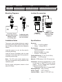
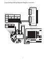
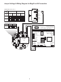
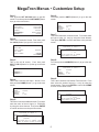
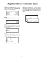
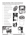
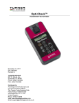
Manual AC-FS-1000 Fouling Sensor by Neosens Quick User Manual Installation Guide Installation Instructions: 1. Install the probe on pipe. (see page 2) 2. Remove the screw from the sensor head. 3. Open the sensor head in a dry environment, away from water and humidity. 4. Unscrew seal connector and pass through the 6 wire cable (1 pair for power, 2 pairs for analog outputs). 5. Wire the 3 pairs following opposite schematics 6. Pull on cable and tighten the seal connector. Set jumper to organic or inorganic depending upon fouling most likely to experience based on installation point. (see page 3 & 4) (Note: Sensor cannot distinguish between organic and inorganic fouling) 7. Close the sensor head. 8. Reposition screw and tighten. Advantage Controls P.O. Box 1472 Muskogee, OK 74402 Phone: 800-743-7431 Fax: 888-686-6212 www.advantagecontrols.com email: [email protected] 5/2010 Analog Output #1 #2 Measurement Type Range Biofilm/fouling thickness Active 4-20mA @ 250 Ohms 0 to 1 or 5mm (0 to 0.039 or 0.197 in) Temperature Active 4-20mA @ 250 Ohms Included Accessories: Glues in here if needed Mounting Diagrams: 0 to 160°C (32 to 320°F) Direct Pipe Thread Mounting with included Adapters A and B (on existing pipe) Adapter A (1” male slip) Tee Mounting with included Adapter A (tee not included) Adapter B (1” MNPT x 1” slip) Must be used in conjunction with Adapter A Installation Notes Specifications The sensor cannot distiguish between organic (biofouling) and inorganic (scale) fouling, but the type of fouling is influenced by the installation location. Electrical: • Input: 8-18 VDC @ 60mA • Output: 4-20mA (500 Ω) Environment: • Ambient temperature - 0 to 180oF (without PVC adapter) • Relative humidity - 0 to 100% • Pressure - 125 PSI Max Install the sensor in a cool, low flow area for monitoring biofouling. Install the sensor immediately after the heat exchanger in the hottest part of the system for monitoring scale fouling. Fouling Monitoring:0-1 mm (0 to 0.039 in) Accuracy:1% of Full scale Note: The PVC quick release adaptor may not have a temperature rating suitable for this installation point. Material: PEEK (body) & 316L SS (sensor tip) Connection: Sensors are supplied with a 1” (2.54 cm) slip and a 1” MNPT PVC quick release adaptor. The PVC adaptor has a maximum temperature rating of 125oF. • Peak sensor body has 1/2” straight BMPT Set the jumper configuration shown on front page accordingly. Shipping Weight: 4 lbs (1.814 kg) Sensor Length: 9.375” (23.8 cm) Insertion Depth: Approx. 3.375” (8.57 cm) Jumper Settings & Wiring Diagram for MegaTron Connection 4-20mA Input Card J2-8 4-20mA Input 84-20mA Input 8+ 4-20mA Input 74-20mA Input 7+ 4-20mA Input 64-20mA Input 6+ 4-20mA Input 54-20mA Input 5+ NORMAL MODE (RUNNING MODE) J1 J2-1 Type Organic ** Range Filter Activation Output Filter ON ** Inorganic Output Filter OFF Output Filter ON J1-8 4-20mA Input 44-20mA Input 4+ Output Filter OFF 4-20mA Input 34-20mA Input 3+ 0 to 5 mm 4-20mA Input 24-20mA Input 2+ 4-20mA Input 14-20mA Input 1+ 0 to 1 mm ** J1-1 ** Default configuration CALIBRATION MODE (TEST MODE) J1 LED 0...9-18 VDC GND OUTPUT #1 - OUTPUT #2 - Both Outputs OUTPUT #1 + 20mA OUTPUT #2 + 4mA MegaTron Mother Board T3 Q2 R26 U18 R7 T4 R22 U12 U13 R4 R21 MH1 C28 C26 C2 U2 R28 R35 D2 Eprom T2 R24 R27 R23 Q1 7 ! +5 +5 GND -12 +12 C27 WARNING 0...9-18Vdc R30 P10 D1 6 Q4 C30 J1 C29 R17 Card Slots 3 4 5 Q3 MH2 T1 R11 R31 P2 R25 P3 ! 2 P1 R14 U8 C1 R32 C8 1 C34 Calibration Note: The number of channels or 4-20mA inputs depends on on the number ordered. Relay Card Outputs Incoming Power 16-20 11-15 6-10 1-5 Jumper Settings & Wiring Diagram for MegaTron SS Connection Part # SS-MAI-2 NORMAL MODE (RUNNING MODE) J1 Type Range Filter Activation Input 1 - Organic ** Output Filter ON ** Input 1 + Inorganic Output Filter OFF Output Filter ON Output Filter OFF Input 2 Input 2 + Rev D 0 to 5 mm 0 to 1 mm ** Input 3 Input 3 + MegaTron SS 4-20mA Input ** Default configuration CALIBRATION MODE (TEST MODE) J1 U18 T2 R7 Flow Switch ORP ORP pH pH Ground Drum Level 5 Drum Level 4 Drum Level 3 Ground Drum Level 2 Drum Level 1 Water Meter Ground Water Meter 2 Signal Water Meter 1 Signal Red Black Green White Red Black Black Red +5 VDC Ground Ground Ground W W W R All 3 Incoming Power T4 R22 U12 R21 U13 R4 C2 MH1 C28 C26 Note: Use 22 AWG (.76 mm) twisted pair shielded wire for all of these low voltage signal connections. Processor Key Pad Ribbon Cable Connection U2 R28 R35 Q1 R24 R27 R23 D2 ! +5 +5 GND -12 +12 R26 R30 P10 D1 Conductivity Temperature Q3 MH2 Q2 WARNING 0...9-18Vdc Q4 C30 J1 C29 C27 R32 T3 R14 T1 R11 R31 P2 R25 P3 C1 Communications Program / Memory Card Connection Card Connection P1 R17 Aux Flow Aux Flow C8 U8 ! Aux Flow PIC Chip Signal Aux Flow 3 Signal Aux Flow 2 Signal Aux Flow 1 Aux Flow +5 vdc B Ground B Ground 0...9-18 VDC GND OUTPUT #1 - OUTPUT #2 - Both Outputs OUTPUT #1 + 20mA OUTPUT #2 + 4mA C34 Calibration Display Ribbon Cable Connection LED Cable Relay Card Ribbon MegaTron Menus • Customize Setup Step 1: First, push the SET UP RUN button to get this screen. From here push the CUSTOMIZE (Button 4) to go to the next screen. Step 6: From here push the UNITS (Button 2) to go to the next screen. >CUSTOMIZE mA INPUT 1< >HOME SETUP< SETPOINTS CALIBRATION TIMERS CUSTOMIZE ALARMS DATE/TIME CONFIGURE HISTORY WATER METER RELAYS Step 2: This is the Customize Screen. From here push the mA IN (Button 9) to go to the next screen. NAME FOULING UNITS NUMBER mm x.xxx Step 7: This is the Customize mA Units screen. From here select the type of units (i.e. mm) by using the Arrow buttons. Then press ENTER to confirm and return to the previous screen. >CUSTOMIZE< >CUSTOMIZE mA INPUT 1< UNIT NAME RELAY NAMES SYS NAME INPUT NAMES NAME FOULING TYPE OFmm UNITS UNITS NOTEPAD NUMBER mA IN RUN SCREEN Step 3: This is the mA IN screen. From here push INPUT 1 OR 2 (Button 1 or 2) then go to the next screen. x.xxx -> mm USE UP/DOWN KEYS TO CHANGE PRESS ENTER TO ACCEPT Step 8: From here push the NUMBER (Button 3) to go to the next screen. >CUSTOMIZE mA INPUT 1< >CUSTOMIZE mA INPUTS< INPUT 1 INPUT 2 NAME FOULING UNITS NUMBER mm x.xxx Step 9: Step 4: This is the Customize mA Input 1 Screen. From here push the NAME (Button 1) to go to the next screen. This is the Customize mA Number Format screen. From here select the number format (i.e. x.xxx) by using the Arrow buttons. Then press ENTER to confirm and HOME to return to the Home screen. >CUSTOMIZE mA INPUT 1< NAME FOULING UNITS NUMBER mm x.xxx >CUSTOMIZE mA INPUT 1< NAME FOULING NUMBER mm FORMAT UNITS NUMBER x.xxx-> X.XXX USE UP/DOWN KEYS TO CHANGE PRESS ENTER TO ACCEPT Step 5: This is the Customize mA Name screen. From here enter the name of the mA Input (i.e. FOULING) by using the Arrow buttons. Then press ENTER to confirm and return to the previous screen. >CUSTOMIZE mA INPUT 1< NAME FOULING mA INPUT UNITS mm1 NAME NUMBER x.xxx [FOULING ] USE ARROW KEYS TO CHANGE, PRESS ENTER TO ACCEPT OR BACK TO ERASE MegaTron Menus • Calibration Setup Step 1: Step 5: First, push the SET UP RUN button to get this screen. From here push the CALIBRATION (Button 2) to go to the next screen. This is the mA Input MAX screen. From here adjust the MAX reading by using the number keys (MAX should be set to 1.000 mm and MIN should be set to 0.000 mm). Then press ENTER to confirm and return to the previous screen. >HOME SETUP< SETPOINTS CALIBRATION TIMERS CUSTOMIZE ALARMS DATE/TIME CONFIGURE HISTORY WATER METER RELAYS Note: All other mA Input Calibration settings can be adjusted in the same fashion beginning at Step 4. >mA INPUT CALIBRATION< Step 2: 20 mA This is the Calibration Screen. From here push the mA IN (Button 7) to go to the next screen. >CALIBRATION< SENSORS USE NUMBER KEYS TO CHANGE, PRESS ENTER TO ACCEPT OR BACK TO ERASE mA OUT mA IN Step 3: This is the Curren Loop Calibration screen. From here push INPUT 1 OR 2 (Button 1 or 2) then go to the next screen. >CURRENT LOOP CALIBRATION< INPUT 1 INPUT 2 Step 4: This is the mA Input Calibration Screen. From here choose the MAX or MIN (Button 3 and 4) to go to the next screen. >mA INPUT CALIBRATION< 20 mA 19649 4 mA MAX MIN OFFSET 3913 1.000 mm 0.000 mm Enabled 19649 4 mA 3913 MAX 1.000 mm 1 MAX MINmA INPUT 0.000 mm(1.000 mm) [_. ] mm OFFSET Enabled Get the Advantage in Water Treatment Equipment Advantage Controls can give you the Advantage in products, knowledge and support on all of your water treatment equipment needs. Cooling Tower Controllers Boiler Blow Down Controllers Blow Down Valve Packages Solenoid Valves Water Meters Chemical Metering Pumps Corrosion Coupon Racks Chemical Solution Tanks Solid Feed Systems Feed Timers Filter Equipment Glycol Feed Systems Pre Fabricated Systems Get the Advantage