1
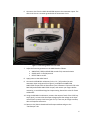
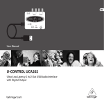
6. Connect a wire from the ANDY board GEN output to the attenuator inputs. The GEN circuit shares a common ground with the attenuator circuit. Figure 3: Connecting cables to the UCA202 7. Adjust the function generator on the ANDY board as follows: •
•
•
AMPLITUDE, FREQ and FINE FRQ controls fully counterclockwise SHAPE switch in the SIN position OFFSET SW set to OFF 8. Apply power to the ANDY board. 9. Connect the RSR MY‐64 multimeter (in the 2 V ~ [AC] position) to each attenuator input and ground (see Figure 2), and adjust the ANDY GEN AMPLITUDE trimpot until the attenuator input is between 0.740 and 0.745 volts RMS. Adjust the ANDY AMPLITUDE trimpot, and remove your fingers before measuring, to avoid disturbing the trimpot setting. Record this value for future calculations. 10. Using the RSR MY‐64 multimeter, measure the output of each of the LF356 op‐
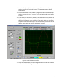
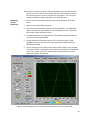
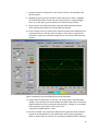
amps (pin 6), to insure that the output voltage equals the voltage at the input resistor (each op‐amp circuit has a gain of 1.0). There may be a slight variation, due to component tolerances. 11. Return to the Zeitnitz Soundcard Oscilloscope window and go to the “Oscilloscope” tab. 6