1
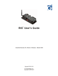
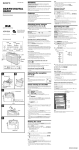
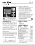
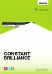
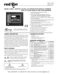
TM
Rio LINK User’s Guide
Industrial Wireless Modem - Model G306C
2010-01-28
G3 Technologies, Inc.
Copyright © 2009-2010
Table of Content
Introduction . . . . . . . . . . . . . . . . . . . . . . . . . . . . . . . . . . . . . . . . . . 1
Features . . . . . . . . . . . . . . . . . . . . . . . . . . . . . . . . . . . . . . . . . . . . 1
Specifications . . . . . . . . . . . . . . . . . . . . . . . . . . . . . . . . . . . . . . . . 2
External Interface & Setup . . . . . . . . . . . . . . . . . . . . . . . . . . . . . . 3
Power Input Connection . . . . . . . . . . . . . . . . . . . . . . . . . . . 3
Serial Port Connection . . . . . . . . . . . . . . . . . . . . . . . . . . . . 3
RS-232 (DCE). . . . . . . . . . . . . . . . . . . . . . . . . . . . . . 3
RS-485 2-wire . . . . . . . . . . . . . . . . . . . . . . . . . . . . . . 3
RS-485 4-wire . . . . . . . . . . . . . . . . . . . . . . . . . . . . . . 4
DIP Switch S1 function . . . . . . . . . . . . . . . . . . . . . . . . . . . . 4
RF Modem Operation . . . . . . . . . . . . . . . . . . . . . . . . . . . . . . . . . . 4
RF Modem Configuration . . . . . . . . . . . . . . . . . . . . . . . . . . . . . . . 5
Reset Pushbutton . . . . . . . . . . . . . . . . . . . . . . . . . . . . . . . . 5
Selecting an RF Net Code (Hopping Channel) . . . . . . . . . . 5
Installing X-CTU Utility from Digi International . . . . . . . . . . 5
Using X-CTU to configure RF Net Code . . . . . . . . . . . . . . . 5
Step One. . . . . . . . . . . . . . . . . . . . . . . . . . . . . . . . . . 5
Step Two . . . . . . . . . . . . . . . . . . . . . . . . . . . . . . . . . . 6
Step Three . . . . . . . . . . . . . . . . . . . . . . . . . . . . . . . . 6
Loading Firmware Version 5000 . . . . . . . . . . . . . . . . . . . . . 7
Advanced Configuration Options . . . . . . . . . . . . . . . . . . . . 7
Antenna & RF Considerations . . . . . . . . . . . . . . . . . . . . . . . . . . . 8
Ordering Information . . . . . . . . . . . . . . . . . . . . . . . . . . . . . . . . . . . 8
Warranty . . . . . . . . . . . . . . . . . . . . . . . . . . . . . . . . . . . . . . . . . . . . 8
Contact Information. . . . . . . . . . . . . . . . . . . . . . . . . . . . . . . . . . . . 8
Contact Information
G3 Technologies, Inc.
2536 W. 239th St.
Louisburg, KS 66053
Ph 913-963-7300
Fax 913-964-3010
E-mail: [email protected]
Web site: www.g3ti.com
i
Introduction
This guide covers the operation, installation and configuration options of the RioLink, Industrial Wireless
Modem - Model G306C. Refer to the G306C Data Sheet for quick reference.
The Model G306C wireless modem is an industrial grade high performance spread-spectrum (FHSS)
radio with selectable RS232 or RS485 data interface.
The RioLink modem provides out-of-box wireless connectivity for standard asynchronous serial data
between RS232 and/or RS485 devices, and is transparent to the user’s protocol. It provides an easy and
reliable data link between points where wiring is impractical or impossible. Models are available for
900MHz or 2.4GHz ISM band frequencies, and either 9600 baud (standard) or 19.2K baud data rates.
The RioLink is also system-compatible with Wireless I/O units from G3 Technologies. It is used to
interface the Master Controller’s Modbus serial port to the Wireless I/O data communications network,
and can also be used to connect third-party devices into the same wireless network.
By using RioLink, virtually any Modbus Master Controller (PC, PLC, Touch-screen controller, RTU & etc)
or HMI package (G3’s VUE, Wonderware, Citect, Intellution, Cygnet, Lookout, & etc) can communicate
with G3’s Wireless I/O units (models G303 RIO, G308 RioExpress, G309 RioLogic, & etc).
Features
•
•
•
•
•
•
10-30 Vdc Input Power, very low power consumption.
•
•
•
Simple AT and Binary commands for modem programing, or simple-to-use X-CTU (free download).
Long range: Up to 7 miles with whip antenna, up to 20 miles with high-gain antenna (line-of-sight, 900MHz).
Out-of-box RF communications using factory default configuration settings.
Simple DIP Switch settings to select RS232, RS485 2-wire or RS485 4-wire data interface.
True peer-to-peer (no master/slave dependencies), point-to-point, point-to-multipoint, multidrop.
Advanced Networking & Security features: FHSS (Frequency Hopping Spread Spectrum), 7 hopping
channels (each with over 65,000 available network addresses), Retries & Acknowledgments.
CSA certification for Class 1, Div 2, Groups A,B,C,D use in USA and Canada
Free expert Technical Support
Integrated
RF Module
Mounting ears
(DIN Rail optional)
Antenna
Connection
DB-9 Data & Pwr
Connector
Power Input
Pwr & Data
LEDs
(latching connector)
Reset
pushbutton
DIP Switch S1
Figure 1
G306C Layout
1
Specifications
Radio Performance:
Indoor/Urban Range
(w/ 2.1 dB dipole antenna)
Outdoor RF line-of-sight Range
(w/ 2.1 dB dipole antenna)
Outdoor RF line-of-sight Range
(w/ high gain antenna)
Transmit Power Output
Receiver Sensitivity
Data Communications:
Data Protocol
Data Rate
Handshaking
Networking & Security:
Frequency Range
Spread Spectrum
Network Topologies
Network Channels
Network Filtration Layers
Advanced Functions
Power Requirements:
Input Voltage, Power
Current, Receive/Standby (IRX)
Current, Transmit (ITX)
Physical:
Power Connector
Data Connector
Antenna Connector
Dimensions
Weight
Mounting
Miscellaneous:
Surge protection
Operating Temperature
Humidity
Certifications
Use Limitation Warning:
900MHz, up to 1500' (450m); 2.4GHz, up to 600' (180m)
900MHz, up to 7 miles (11km); 2.4GHz, up to 3 miles (5km)
900MHz, up to 20 miles (32km); 2.4GHz, up to 10 miles (16km)
900MHz, 100mW; 2.4GHz, 50mW
900MHz, -110dBm; 2.4GHz, -107dBm
Protocol independent (uses standard asynchronous serial data)
9600 baud (bps), 19.2K optional (Interface and Throughput data rate)
None: TX and RX data only (RTS is not used & CTS is fixed active)
ISM 902-928MHz or 2.4000-2.4835GHz
Frequency Hopping Spread Spectrum (FHSS)
Peer-to-peer (no master/slave dependencies), Point-to-point, Point-tomultipoint and Multi-drop.
7 Channels (selects RF hopping sequence), shared 25 frequencies,
“RF Net Codes” 0-6, Default = “0”
Vendor ID (VID), Hopping Channel, Destination Address
Optional Repeater, Power-save & data security modes
10-30 Vdc, 100mA max, self-resetting 500mA fuse, over-voltage &
reverse-voltage protected
IRX = 35mA (900MHz), 45mA (2.4GHz) @12Vdc
ITX = 85mA (900MHz), 90mA (2.4GHz) @12Vdc
2-pin polarized latching connector (48” mating power cord is included).
Also may be powered through DB9 data connector
DB9-female
RP-SMA, 50 ohms unbalanced
3.0”W x 3.75”L x 1.3”H plus connectors and mounting ears
(3.93”W x 4.25”L x 1.35”H overall)
6.8 oz. (200g)
Panel mount 1.0” x 3.5” rectangular hole pattern
#6 or #8 pan-head screws recommended
Optional mounting clip available for DIN Rail mounting
Power & serial port connections meet or exceed min standards for ESD,
EFT, and Surge withstand per the international IEC 1000-4 standards
-40 to 85 degrees C
5-95% non-condensing
FCC Part 15 Class A
CSA C/US Class I, Div 2, Groups A,B,C,D Temp Code T4
This product is not to be used for personal protection or for any form of
life support.
2
External Interface & Setup
Power Input Connection: The RioLink can be powered either through the polarized latching connector
(using the supplied power cable), or through the DB9 connector along with the data. The unit does not
have a Power ON/OFF Switch, so power is applied or removed by engaging or disengaging the connector
being used to apply power, or by externally switching the source of the power.
Serial Port Connection: The TX and RX data connects through the DB9 connector, and is selectable for
either RS232, RS485 2-wire, or RS485 4-wire using the 5 position DIP Switch (S1).
To access the DIP Switch for selecting the desired Data Interface, 1) remove power from the unit, 2)
remove the 4 screws on the top of the cover and 3) lift the cover off. After setting the DIP Switches as
desired, replace the cover before powering the unit.
The examples below describe the setup and connection for each of the Data Interface types.
RS-232 (DCE): (Factory default settings)
DIP Switch settings for RS-232 interface:
N
O
S1
RS-485
485 2-wire
485 2-wire
485 2-wire
485 Termination
1 2 3 4 5
RS-232
RS-232
RS-485
4-wire RS-232
RS-232
RS-232
PIN 3
TXD
PIN 5
GND
PIN 2
RXD
1
PIN 9
+VIN
PIN 8
CTS
Switch positions 1-5 all in the OFF position
DB-9 pin connections for RS-232 interface:
1.
2.
3.
4.
5.
6.
7.
8.
9.
(no connection)
Receive Data output (RXD)
Transmit Data input (TXD)
(no connection)
Power Common (GND)
(no connection)
(no connection)
CTS (fixed active)
Power Positive (+Vin = 0-30Vdc)
Figure 2
RS-485 2-WIRE:
DIP Switch settings for RS-485 2-wire interface:
N
O
S1
RS-485
485 2-wire
485 2-wire
485 2-wire
485 Termination
1 2 3 4 5
RS-232
RS-232
RS-485
4-wire RS-232
RS-232
RS-232
PIN 2
T/R-
PIN 5
GND
1
PIN 9
+VIN
Figure 3
PIN 8
T/R+
Switch positions 1-4 in the ON position
Switch position 5 is OFF unless Termination is needed
DB-9 pin connections for RS-485 2-wire interface:
1.
2.
3.
4.
5.
6.
7.
8.
9.
(no connection)
Transmit/Receive Neg (T/R-)
(no connection)
(no connection)
Power Common (GND)
(no connection)
(no connection)
Transmit/Receive Pos (T/R+)
Power Positive (+Vin = 0-30Vdc)
3
External Interface & Setup (cont’d):
RS-485 4-WIRE:
DIP Switch settings for RS-485 4-wire interface:
N
O
S1
PIN 5
GND
RS-485
485 2-wire
485 2-wire
485 2-wire
485 Termination
1 2 3 4 5
RS-232
RS-232
RS-485
4-wire RS-232
RS-232
RS-232
PIN 3
R-
PIN 2
T1
PIN 9
+VIN
PIN 8 PIN 7
T+
R+
Figure 4
Switch position 1 in the ON position
Switch positions 2-4 in the OFF position
Switch position 5 is OFF unless Termination is needed
DB-9 pin connections for RS-485 4-wire interface:
1.
2.
3.
4.
5.
6.
7.
8.
9.
(no connection)
Transmit Neg (T-)
Receive Neg (R-)
(no connection)
Power Common (GND)
(no connection)
Receive pos (R+)
Transmit Pos (T+)
Power Positive (+Vin = 0-30Vdc)
DIP Switch S1 function:
Pin 1
Pin 2
Pin 3
Pin 4
Pin 5
---------------------
Selects between RS-232 (OFF) and RS-485 (ON)
Turned ON when using RS-485 2-wire to block data echo.
When ON it connects RS-485 T- and R- to become T/R- for RS-485 2-wire.
When ON it connects RS-485 T+ & R+ to become T/R+ for RS-485 2 wire.
When ON it connects a 120 ohm (cap coupled) load between R+ & R- to provide RS-485
Termination when needed. Termination is normally needed only when operating RS-485
over a relatively long distance and/or at high data rates.
RF Modem Operation
RS-232 and RS-485 Data Flow: Devices with a UART serial port and either RS-232 or RS-485 data
interface can connect directly to the G306C Wireless Modem (see connection information above).
Serial communications between a host and a G306C RF Modem are dependent upon having matched
settings for baud rate and bite structure. The standard model of G306C operates at 9600 baud, but 19.2K
baud model is available. The bite structure is “8N1” (8 data bits, no parity & 1 stop bit).
Data flow uses only TX and RX data (no hand-shaking). When using RS-232, CTS is fixed active and
RTS is not used.
The LEDs on the face of the G306C allow the user to observe the Power (PWR), the serial Transmit Data
(TXD) and Receive Data (RXD) of the RF Modem.
4
RF Modem Configuration
Hardware settings for the RS-232/RS-485 data interface using the 5 position DIP Switch located under
the cover is described under “External Interface & Setup” on previous pages.
The G306C RF Modem comes from the factory with standard software configuration settings that are
suitable for most applications. These parameters seldom require changing.
Reset Pushbutton:
The Reset pushbutton located under the cover (see Figure 1) re-initializes the unit with the configuration
parameters that were last loaded in the unit. This pushbutton could be used in the rare event that the unit
“hangs up” and stops functioning. It does the same thing as power-cycling the unit.
Selecting an RF Net Code (Hopping Channel):
For typical applications, the only software parameter that will need to be changed, and that only for
certain unique situations, is the RF Net Code.
The RF Net Code default is “0”, but can be set for any one of 7 (0-6) different pre-defined hopping
sequences used by the Frequency Hopping Spread Spectrum (FHSS).
Only units on the same RF Net Code will hear/respond to each other. Therefore, in situations where
multiple wireless networks needs to co-exist, the RF Net Code can be set at different values for each of
the networks to provide isolation between them.
NOTE: If using the G306C Wireless Modem to communicate with Wireless I/O units from G3
Technologies (RioExpress, & etc), note that the RF Net Code selection on the G306C and on the
Wireless I/O unit(s) much match in order for them to communicate with each other.
Installing X-CTU Config. Utility from Digi International:
The G306C contains an integrated “XStream” RF Module from Digi International. “X-CTU” is a
configuration utility provided by Digi International as a free download from their website. It is used to
make software configuration changes to the Xstream RF Module contained in the G306C.
To download and install X-CTU, go to www.digi.com and do a search for “X-CTU”. It will open a page
where you can select to download the X-CTU Installer. Follow on-screen instructions.
Using X-CTU to configure RF Net Code:
Step One:
PC and G306C Setup.
1. The PC must have an available RS-232 serial port. If USB is all that is available on the PC, a USB-toRS232 adaptor can be used.
2. X-CTU must be properly installed on the PC (see instructions above).
3. Use a straight-through DB-9 RS-232 cable to connect between the PC serial port and the G306C.
4. With the G306C DIP Switches set for RS-232 (factory default), connect power (10-30Vdc) to the
G306C Wireless Modem using the provided power cable.
With the PC and G306C set up as described, continue to the next steps to configure the software
parameters in the G306C Wireless Modem.
5
Using X-CTU for Modem configuration (cont’d):
Step Two:
Open X-CTU and establish communications with the
G306C Wireless Modem:
1. Double-click the X-CTU icon to open the utility.
2. On the “PC Settings” tab (opening screen), select
the desired Comm Port from the list of those available.
3. Verify that Baud rate is set to match that of the
G306C (baud rate is shown on G306C label - most
common is 9600 baud), Parity = “None”, Data Bits = “8”
and Stop Bits = “1”.
4. Click on the “Test / Query” button to test
communications between X-CTU and the G306C. A
pop-up (shown below) will indicate the query results. If
successful, continue to the next step. Otherwise, recheck setup and settings described above and try
again.
Figure 5
Step Three:
Read the existing Parameter Settings on the G306C,
and select new values for the parameters to be
changed (RF Net Code, in this example).
1. Select the “Modem Configuration” tab, and then
click on the “Read” button. After a few seconds the
blank screen will be filled in with a list of the current
software parameter settings read from the G306C.
2. Verify that the firmware “Version” = 5000. (If it is not
“5000”, go to the instructions on the next page for
loading a new firmware version onto the unit.)
3. Locate the line near the top of the parameter
display that reads “(0) HP-Hopping Channel”. That
indicates that the Hopping Channel (RF Net Code) is
currently set at “0” (default).
4. To change the RF Net Code, click on the “Hopping
Channel” line and enter the value of your choice (0-6).
Important: The radio’s “CS” parameter (listed under
“Serial Interfacing”) is factory set at the non-default
value of “3” for “RS485 Enable High”. Be sure CS
remains set properly before proceeding to step 5.
Figure 6
5. Click the “Write” button to load the new value into
the G306C. A note at the bottom of the X-CTU screen
will indicate that the Write cycle was successful.
6. Again click “Read” and verify that the new selected
value reads back correctly.
This completes the configuration of a new RF Net Code (Hopping Channel). Note that X-CTU allows you
to “Save” (and “Load”) configuration parameter files on your PC.
6
Using X-CTU for Modem configuration (cont’d):
If for some reason the unit is loaded with a firmware version other than Version 5000, or if the
configuration gets inadvertently messed up, then follow the instructions that follow:
Loading Firmware Version 5000: (Refer to Figure 6)
At the top edge of the display window on X-CTU, there are drop-downs for selecting “Modem Type”,
“Function Set” and “Firmware Version”.
1. Select the XStream Modem Type:
X09-009 = 900MHz 9600 baud (used in model G306C-04) - Standard Model
X09-019 = 900MHz 19.2K baud (used in model G306C-06)
X24-009 = 2.4GHz 9600 baud (used in model G306C-08) - Standard Model
X24-019 = 2.4GHz 19.2K baud (used in model G306C-10)
2. Select the Function Set “Hopping - Advanced RF Modes”. The Firmware Version should then show
Version “5000”.
3. Click the “Show Defaults” button. This sets all of the parameters on the screen to their default values.
4. Scroll down to the parameter “CS - DO2 Configuration” (under Serial Interfacing). Click on this line
item and from the drop-down select “3 - RS485 TX Enable High”. This is the only parameter required to
be other than default for the G306C RF Modem.
5. Change the Hopping Channel (RF Net Code) if you wish.
6. Click the “Write” button to load Firmware 5000 and/or the altered parameter(s) into the G306C RF
Modem.
Advanced Configuration Options:
The only advanced feature generally used is the Radio Repeater function. Refer to the Radio Module
User Manual Version 5000 from Digi International for detailed instructions for Repeater configuration. It is
a free download from www.digi.com/support/documentation.
Also, G3 Technologies can assist, and in some cases may be able to supply pre-set configuration files for
Repeater and Repeater End-Node configuration.
There are a number of other advanced functions that can be configured on these radios using the X-CTU
configuration utility, but they generally require a more thorough understanding of the unit’s function and
should be done only by qualified personnel. Digi’s User Manual has detailed information about the
function and configuration of advanced radio features.
NOTE that when using the G306C Wireless Modem with Wireless I/O units from G3 Technologies, the
G306C may not be able to utilize advanced configuration options. Refer to the Wireless I/O User’s Guide
for supported Radio Configuration options.
7
Antenna and RF Considerations
The Rio-Link Wireless Modem (G306C) operates in the ISM 900MHz or 2.4GHz frequency bands. At
these frequencies the RF signal is able to travel a considerable distance line-of-sight (LOS). At the higher
frequencies the RF signal does not “bend” around obstacles like VHF and lower frequency RF signals.
Obstacles in the line-of-sight are generally the key consideration when evaluating the radio
communications path. For short distances of less than a few miles, obstacles such as trees and buildings
can often be overcome by raising the antenna or relocating the equipment. For longer distances or for
situations where raising the antenna height becomes impractical, then the system can be configured to
use a G306C as an RF Repeater in order to extend the effective range.
The antenna connection on the G306C is a reverse-polarity SMA (RP-SMA). For very short distances,
less than 2000 ft in an open area or less than 100 ft within a building or wooded area, a minimum antenna
system can be used. A low profile or dipole whip antenna mounted on or in the enclosure containing the
G306C may be suitable. For distances up to a few miles LOS a dipole antenna mounted six or more feet
above the ground is suitable. For longer distances a higher gain directional Yagi antenna is
recommended. When using a pole mounted antenna it is recommended that a coaxial lightning arrestor
be used. Also, as the length of the coaxial cable connecting the G306C to the antenna increases, it
becomes more important to use low-loss coaxial cable.
Helpful hint: If RioExpress or RioLogic Wireless I/O units are being used in the wireless network,
their RSSI (Receive Signal Strength Indicator) is useful in evaluating the RF signal strength over a
given path. The RSSI LEDs are updated after each valid communications with the Wireless I/O
device. There are three green LEDs used to visually indicate a relative RSSI value. All three lights
indicate a strong RF signal, two lights indicate a moderate RF signal, and one light indicates a
weak/marginal RF signal. Note that the RSSI LEDs time out and turn off after 10 seconds, and then
are updated again with the next valid data message.
Ordering Information
Part Number: G306C-04
G306C-04E
G306C-08
G306C-08E
RioLink Wireless Modem (900MHz 9600 baud)
Starter Kit: 2 ea. RioLink Modems (900MHz), & Accessories (whip
antennas, power supplies, RS-232 cables and Documentation)
RioLink Wireless Modem ( 2.4GHz 9600 baud)
Starter Kit: 2 ea. RioLink Modems ( 2.4GHz), & Accessories (whip
antennas, power supplies, RS-232 cables and Documentation)
Note that Starter Kits are available for the RioExpress Wireless I/O (model G308) that include the G306C
Wireless Modem along with the Wireless I/O. NEMA 4X packages are also available. For pricing,
availability and other product options please contact G3 Technologies.
Warranty
This product is covered by a one year limited warranty against defects in material and workmanship. The
full warranty statement as well as the Terms & Conditions of Sale are available from the G3 Technologies
web site.
Contact Information:
For product support and further information, contact G3 Technoloiges.
G3 Technologies, Inc.
2536 W. 239th St., Louisburg, KS 66053
Ph 913-963-7300
Fax 913-964-3010
E-mail: [email protected]
Web site: www.g3ti.com
8
G306 Wireless Modem Revision History:
1) G306: Original product release 2003. Non CSA certified, RS232 only, +V=10-16Vdc, pluggable screw
terminal for +V.
2) G306A: Introduced 2008. Interim model (pre CSA approval), added DIP Switch selection for RS232,
RS485 4-wire & RS485 2-wire, increased range of +V=10-30Vdc, changed to latching connector for +V.
3) G306C: Introduced July 2009. CSA certified for Class I, Div 2 Grps A,B,C,D in USA and Canada.
Added DIP Switch “data echo disable” for RS485 2-wire.
9