1
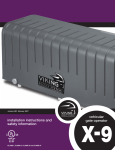
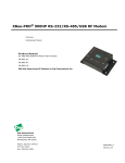
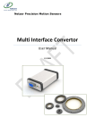
TM
RIO User’s Guide
Industrial Remote I/O, Wired or Wireless - Model G303
Revised 2010-01-28
G3 Technologies, Inc.
Copyright © 2004-2010
Table of Content
Introduction . . . . . . . . . . . . . . . . . . . . . . . . . . . . . . . . . . . . . . . . . . 1
Specifications . . . . . . . . . . . . . . . . . . . . . . . . . . . . . . . . . . . . . . . . 2
Input Power . . . . . . . . . . . . . . . . . . . . . . . . . . . . . . . . . . . . . . . . . . 4
Grounding . . . . . . . . . . . . . . . . . . . . . . . . . . . . . . . . . . . . . . . . . . . 4
Digital Input Description & Wiring Diagram . . . . . . . . . . . . . . . . . . 5
Digital Output Description & Wiring Diagram . . . . . . . . . . . . . . . . 6
Analog Input Description & Wiring Diagram . . . . . . . . . . . . . . . . . 7
Pulse Totalizer/Rate Description & Wiring Diagram . . . . . . . . . . . 8
DIP Switch and Jumper Settings. . . . . . . . . . . . . . . . . . . . . . . . . . 9
LED Indicators & Diagnostics . . . . . . . . . . . . . . . . . . . . . . . . . . . . 10
Modbus Registor Map . . . . . . . . . . . . . . . . . . . . . . . . . . . . . . . . . . 11
Modbus Communications . . . . . . . . . . . . . . . . . . . . . . . . . . . . . . . 13
Modbus Messages Examples . . . . . . . . . . . . . . . . . . . . . . . . . . . . 13
PC/Master Communication Connections . . . . . . . . . . . . . . . . . . . 14
Antenna & RF Considerations . . . . . . . . . . . . . . . . . . . . . . . . . . . 14
Radio Configuration Using XCTU Config Utility . . . . . . . . . . . . . . 15
Mounting Dimensions . . . . . . . . . . . . . . . . . . . . . . . . . . . . . . . . . . 18
Ordering Information . . . . . . . . . . . . . . . . . . . . . . . . . . . . . . . . . . . 18
Warranty . . . . . . . . . . . . . . . . . . . . . . . . . . . . . . . . . . . . . . . . . . . . 18
Revision History . . . . . . . . . . . . . . . . . . . . . . . . . . . . . . . . . . . . . . 19
Contact Information
G3 Technologies, Inc.
2536 W. 239th St.
Louisburg, KS 66053
Ph 913-963-7300
Fax 913-964-3010
E-mail: [email protected]
Web site: www.g3ti.com
G303 User’s Guide (2010-01-28)
i
Introduction
This guide covers the operation, installation and configuration of the RIO industrial grade Remote I/O Model G303.
The RIO is an easy-to-use MODBUS Slave Remote I/O module. Since the RIO is designed for the simple
task of reading inputs and driving outputs using common pre-defined Modbus commands, it requires no
software configuration (except for radio parameters - see Radio Configuration section) and can be polled
from most any Modbus Master. For wireless RIO models, a compatible SS Radio Modem (i.e. Model
G306C Wireless Modem) is used on the Master’s serial port.
The RIO is a low-power and environmentally tolerant device that provides reliable access to remote or
hard-to-reach Digital & Analog process signals for both monitoring and control, and is suitable for solar
powered outdoor sites. Models are available for wired (RS485 and RS232) or integrated wireless (high
performance FHSS Radio) data communications.
* NOTE:
DIP switches and J14 are exposed
in this image for example only.
Optional data port connection
(RPSMAF antenna connector or RS232 DB9M)
To meet Class I, Div 2
requirements the cover must
be removed (four screws) to
access Jumper J14 and DIP
switches S1 & S3, and they
should not be changed unless
the area is known to be
non-hazardous.
RS485 Data Port
(expansion port when
using integrated radio)
Analog Inputs
DIP Switch S3*
+V Power Input
Vx select, jumper J14*
DIP Switch S2
DIP Switch S1*
Pulse Input
Digital Outputs
Digital Inputs
Status LEDs
Figure 1
G303 User’s Guide (2010-01-28)
1
Specifications
Data Communications:
Serial Data Comm.
Data Rate (throughput)
Modbus Address
Slave Comm Fail Action
Modbus RTU Slave mode protocol, 8N1 bite structure, and selection of
600, 1200, 9600 & 19.2K baud rate. Integrated options are:
1) RS485 only for wired multi-drop networks, 2 wire or 4 wire
2) 900MHz or 2.4GHz FHSS radio and 2 or 4 wire RS485 expansion.
3) FSK Modem for interface to external audio-input radios
4) RS232 DTE DB9M for wired or 3rd-party-radio networks
Per baud rate setting, but with restrictions on wireless models.
255 (8 bit DIP Switch) Device Addresses
May be accomplished by writing to timed Digital Output.
Low-power Spread Spectrum Radio option (900MHz 100mW & 2.4GHz 50mW models):
Indoor/Urban Range
900MHz, up to 1500' (450m); 2.4GHz, up to 600' (180m)
(w/ 2.1 dB dipole antenna)
Outdoor RF line-of-sight Range
900MHz, up to 7 miles (11km); 2.4GHz, up to 3 miles (5km)
(w/ 2.1 dB dipole antenna)
Outdoor RF line-of-sight Range
900MHz, up to 20 miles (32km); 2.4GHz, up to 10 miles (16km)
(w/ high gain antenna)
Receiver Sensitivity
900MHz, -110dBm; 2.4GHz, -107dBm
Transmit Power Output
900MHz, 100mW; 2.4GHz, 50mW
Baud Rate
9600 or 19.2K baud (dictated by SS Radio being used)
Radio Channels
7 ea. RF Channels (hopping channels)
Radio Configuration
Use XCTU Config Utility (see Radio Configuration section)
1 Watt Spread Spectrum Radio option (900MHz only):
Indoor/Urban Range
Up to 3000' (900m) at 9600 baud
(w/ 2.1 dB dipole antenna)
Outdoor RF line-of-sight Range
Up to 14 miles (22km) at 9600 baud
(w/ 2.1 dB dipole antenna)
Outdoor RF line-of-sight Range
Up to 40 miles (64km) at 9600 baud
(w/ high gain antenna)
Receiver Sensitivity
-110 dBm
Transmit Power Output
1mW to 1Watt, software configured
Baud Rate
1200, 9600, 19.2K baud, software configured (must be configured to
match DIP Switch baud rate settings).
Radio Channels
10 ea. RF Channels (hopping channels)
Radio Configuration
Use XCTU Config Utility (see Radio Configuration section)
Discrete I/O:
Digital Inputs (DI)
Digital Outputs (DO)
Analog Inputs (AI)
Pulse Totalizer / Flow Rate /
Event Capture Input:
8 ea. (DI1-8)
Active low (sink to power common), non-latching & optional 30 sec hold
Minimum active input detection 2mS
Optical coupling for surge/noise tolerance & filtering
12V wetting voltage, 5mA wetting current
4 ea. (DO1-4)
Form C, N/O & N/C relay contacts, UL rated at 10 Amps 30Vdc resistive
and 240Vac general use, Pilot Duty B300 & Q300
4 ea. (AI1-4)
0-5V (1-5V) or 0-20mA (4-20mA), Individually DIP switch selectable 250
ohm 0.1% 3W wire-wound resistor on-board for mA input.
Input low-pass RC filter <1000Hz. A/D conversion is 12 bit resolution.
Overall accuracy 0.25% FS, typical accuracy 0.1% FS @ 25° C
Over-voltage tolerance +/-30Vdc
Totalizer (16 bit hdwr, 32 bit sftwr), PPS & PPM Rate. Signal input is
configurable for a variety of input types, having different sensitivity and
frequency response characteristics. See Pulse Input section later in
this document for details.
G303 User’s Guide (2010-01-28)
2
Power:
Input Voltage (+V)
Input Voltage Monitor
Transducer Power (Vx)
Typical Current draw
(@12Vdc)
Total power consumption
Miscellaneous:
Diagnostics
Surge protection
Certifications
Physical:
Operating Temperature
Humidity
Field Wiring Connections
DIP Switches
Enclosure
Dimensions (in.)
Weight
Mounting
Antenna Connection
RS232 Connection
10.5 to 16 Vdc, self-resetting 1A fuse.
Internal analog (AI5) monitors +V, 0-16Vdc range, accuracy +/-1% FS
Jumper selected 12V or 24V, self-resetting 100mA fuse.
1) Base unit = 15mA
2) Each energized DO relay = 12mA
3) Each active Digital Input = 4mA
4) Optional low-power SS radio Standby/Rec = 25mA, Xmit = 65mA
5) Optional 1Watt SS radio Standby/RX = 40mA, TX = 50-340mA
6) RS232 or FSK Modem = 15mA
Total power consumption is the sum of all the internal loads plus any
external loads being supplied. Power consumption is also affected by
Poll Rate since current draw is significantly higher during the Transmit
cycle. Max rating is 600mA @ 12Vdc.
LEDs for CPU status, TX, RX, 8 ea. DIs, 4 ea. DOs and Power.
All power, serial port and I/O connections meet or exceed minimum
standards for ESD, EFT, and Surge withstand per the international
IEC 1000-4 standards
FCC Part 15 Class A
CSA C/US Class I, Div 2, Groups A,B,C,D. Temp. Code: T3C
-40° to 80° C
5-95% relative humidity, non-condensing
All wire connections are pluggable screw terminals, 0.2” spacing
Recommended Screw Torque 4.5 lb-in,12-28 AWG
To meet Class I, Div 2 requirements, cover must be removed (4 ea.
phillips-head screws) to access DIP Switches S1 & S3.
Powder-coated aluminum, non-rated
8.42L x 4.15W x 1.6H overall
19 oz. (500g)
Panel mounting, 7.76” x 2.4” rectangular pattern “key-hole”
#8 pan-head screws recommended
Optional mounting clip available for TS-35 DIN Rail mounting
RPSMA-female (on units with integrated SS radio)
DB9M DTE (on units with RS232 option in place of radio)
G303 User’s Guide (2010-01-28)
3
Input Power
The RIO should be powered from an isolated source. Solar and battery power sources are inherently
isolated. For line voltage connected AC/DC power supplies, verify that they have the proper secondary
isolation. To protect the power supply wiring, a 2A Slow-Blow fuse should be installed in the secondary
AC circuit powering the unit. The +V supply voltage range for the RIO is 10.5-16Vdc.
The RIO is designed with very low power consumption, making it suitable for solar powered applications.
It is also designed to be able to power down the radio as a power-save feature, but the firmware does not
currently support this feature.
The following solar site calculations provide an example of the factors that effect the solar panel and
battery sizing. Because of the many factors that affect the sizing requirements for a solar installation,
please contact G3 Technologies for specifics. We are happy to assist in determining the best
configuration for your application.
Solar Site Example:
RIO w/ radio, 10 sec. poll rate, +V Supply & Vx = 12V nominal
Two (2) Digital Inputs assumed active, 5mA ea.
Two (2) 1-5V Sensors, 3mA ea. (4-20mA sensors would be calculated at full scale 20mA)
Solar Array Size = (ILoad Avg)(24hrs)(12Vdc) / (Average Sun hrs/day)
Where:
ILoad Avg = Average Current Load = (9.9/10sec)(65mA RIO standby) + (0.1/10sec.)(165mA RIO
xmit) + (10mA DI wetting current) + (6mA sensor current) + (6mA Solar Regulator)
ILoad Avg = 88mA = 0.088A
Average Sun hrs/day depends on the geographic location and time of year. For this
example we will use the Winter Average Sun hrs/day for Boise, ID (3.33 hrs/day).
Solar Array Size = (0.088A)(24hrs)(12Vdc) / (3.33 Sun hrs/day)
Solar Array Size = 7.61 Watts (A standard 10W Solar Module could be a good choice.)
Minimum Battery Size = (ILoad Avg)(24hrs)(Days of Autonomy)(Temp. Factor) / (% of Discharge)
Where:
ILoad Avg = 88mA = 0.088A
Days of Autonomy = The number of days without sun that the load current is supplied solely by
the battery. Six to Eight days autonomy is common for 99.9% system
availability.
Temp. Factor =
Batteries are effected by temp. A cold battery will store and supply less
energy. For this example we will use the Boise, ID average January, temp.
of 25 deg. F (1.5 Temp. Factor).
% of Discharge =
The deeper the discharge the shorter the battery life. The % of Discharge
should not be more then 80%.
Minimum amp-hour (Ahr) Battery Size = (0.088A)(24hrs)(8 days)(1.5 Temp. Factor) / (0.8 Discharge)
Minimum Battery Size = 31.7 Ahr (A common 33Ahr battery could be a good choice.)
Grounding
An important item to verify is the proper grounding of the equipment installation. Properly grounded
electrical equipment will be safer, operate with less electrical noise and minimize the potential damage
from power line surges or lightning strikes. We recommend a common point or star grounding
configuration, where all of the equipment in a panel are directly connected to the common grounding
point. The common grounding point is then connected to an 8' ground rod or other suitable grounding
system using #14 AWG or larger copper wire. Check with local regulations for specific grounding
requirements.
G303 User’s Guide (2010-01-28)
4
Digital Input Description & Wiring Diagram
The RIO has 8 Digital Inputs (DI1-8). They are active low, meaning that a DI input is driven (shorted) to
power supply common when active, typically by a dry contact. These inputs can be driven by relay
contacts, switch contacts or open collector transistors. The digital inputs are internally powered with a
wetting voltage approximately equal to the power supply voltage (+V) and a wetting current of 5mA, and
are optically coupled for transient protection and noise filtering. Any pulse or change-of-state that lasts for
more than 2mS will be detected.
In the Digital Input register #3001, the lower 8 bits indicate real-time values for the 8 digital inputs (active
= 1, inactive = 0) and the upper 8 bits are a duplicate except that they hold any active DI for a minimum of
30 seconds. This 30sec hold feature can be used as a “stretched” indication of short duration events.
NOTE: For a single input signal providing a short duration pulse, the Pulse Totalizer/Rate Input can
also be used (see Pulse Input section later in this document). The pulse input provides Modbus
registers for both the accumulated pulse total as well as pulse rate in pulses-per-second (PPS) and
pulses-per-minute (PPM). An event providing an input pulse greater than either 0.35mS (350uS) or
8mS in length (DIP switch selected filtering) will be detected, and can be read either as a totalizer
increment or as a non-zero value in the rate registers. The PPS and PPM rate registers will hold the
non-zero value for 1sec and 1min respectively, effectively providing a pulse-stretching “one shot”.
Also, by using these registers, multiple events occurring in rapid succession will be detected and
recorded.
.
Digital Inputs
Field Wiring Example
+12V
Internal
Logic
(typical of 8)
DI 1
DI 2
RELAY CONTACT
DI 3
SWITCH CONTACT
DI 4
•
•
•
•
O.C. TRANSISTOR
DI 8
GND
Figure 2
G303 User’s Guide (2010-01-28)
5
Digital Output Description & Wiring Diagram
The four digital outputs (DO1-4) are relays with Form C contacts at the screw terminals. They can be
either latched or a timed pulse.
In the latched DO register, bits 1-4 correspond to DOs 1-4. When a “1” is written to one or more of these
bits, the corresponding relay(s) is energized, and when “0” is written the corresponding relay(s) is deenergized. The relays hold their state until the value in the register is changed. The DO registers are set
to “0” upon power-up.
For timed-pulse DOs, each of the four DOs has its own 16 bit register. A single write message can load
one or more (consecutive) of the timed DO registers. They are “count-down” registers decremented
every 100mS (0.1 sec.). Any non-zero value in these registers will energize the corresponding relay, and
the relay will then de-energize when it decrements to zero. A timed DO can be set from 100mS (written
value of “1”) up to 1.8 hours (written value of “FFFF” hex), +0 / -100mS.
In addition to pulsed DO or “Jog” functions for control, this feature can also be used as a “Communication
Loss Timeout” feature. By periodically writing a time value to the Timed DO register that is greater than
the time between writes, the DO relay will remain energized. If communications is interrupted, then the
Timed DO register will time out and de-energize the corresponding DO relay indicating comm loss.
The Timed DO registers are logically OR’d with the Latched DO register bits. Therefore, if a bit is set in
the Latched DO register, the corresponding relay will be energized regardless of the value in the Timed
DO register.
The relay contacts are UL rated for 10A at 30Vdc resistive, 10A at 250Vac general use, 1/4HP 120Vac,
1/2HP 250Vac, B300 and Q300 pilot duty.
Each relay provides 4000 volt contact-to-coil isolation for surge protection.
Digital Outputs
Field Wiring Example
(using normally open contacts)
NC
DO4
Com
NO
LOAD #4
NC
DO3
Internal
Relay
Contacts
-
Com
NO
+
AC or DC Load
Power Supply
LOAD #3
NC
DO2
Com
NO
LOAD #2
NC
DO1
Com
NO
LOAD #1
Figure 3
G303 User’s Guide (2010-01-28)
6
Analog Input Description & Wiring Diagram
Each of the four analog inputs is DIP switch selectable for use with either a 0-5V (1-5V) or 0-20mA
(4-20mA) signal. In order to meet Class I, Div. 2 hazardous location requirements, the cover must be
removed in order to access the DIP switches. To do so, remove the four phillips-head screws on the
cover and lift the cover vertically. The default factory analog input setting is 0-20mA (4-20mA). We
suggest that unused / unterminated analog inputs should be set to 0-20mA (4-20mA). This will bias the
unterminated analog input at zero.
By placing jumper J14, the sensor excitation voltage Vx can be set to either 12Vdc nominal or 24Vdc. In
the 12V setting Vx will be approx the same as the input voltage (+V). In the 24V setting the internal
DC/DC regulator will maintain Vx = 24Vdc over the full 10.5-16Vdc input voltage range. The load on each
Vx terminal should not exceed 20mA.
In solar powered applications where power conservation is a concern, there are practices that can help
lower the power requirements. Using 1-5V rather then 4-20mA sensors is generally recommended. For
sensor power, set Vx selection jumper J14 for 12V if 24V is not required, and set it for “off” if no sensor
power is needed.
The internal Analog Input #5 (AI5) monitors the power input supply voltage (+V), 0-16V voltage range.
The analog to digital converter for all of the analog inputs is 12 bits, providing a 0-4095 decimal count for
zero to full scale inputs.
WARNING: DIP switch and Jumper selections should not be changed unless the area is known to be
non-hazardous.
Analog Input
Field Wiring Example
Internal Logic
Vx
A/D
Filter
+
Vout
AI1
-
GND
250Ω
A/D
Filter
Vx
+
Iout
AI2
-
Typical 3-wire
Voltage Output
Sensor
Typical 2-wire
4-20mA
Sensor
GND
250Ω
Vx
AI3
GND
& etc.
Vx
AI4
GND
Figure 4
G303 User’s Guide (2010-01-28)
7
Pulse Totalizer / Flow Rate / Event Capture Input
Description & Wiring Diagram
The G303 RIO has one (1) specialized pulse input. Associated Modbus registers are provided for pulse
totalization, pulses-per-second (PPS) rate and pulses-per-minute (PPM) rate. This input is also useful for
capturing a periodic event that generates a pulse as short as 0.35mS (350uS), or with filtering that
requires minimum pulse width of 8mS.
No “reset” function is provided for the totalizer or rate registers. However, since the Modbus registers
reside in RAM (volatile) memory, “power-on” initializes them to zero.
Screw terminals are provided for “+” and “-” pulse signal. DIP switch settings (S1-5, S1-6, S1-7) provide
input conditioning for four (4) types of pulse input signals. They are as follows:
1) Turbine meter with inductive pick-up: (S1-5 off, S1-6 off, S1-7 off) Differential input w/ 20K ohm input
impedance for AC sine wave input (no DC component). Input sensitivity is 80mV p/p at 10 Hz, and 2.0V
p/p at 2.5KHz.
2) Logic level pulse signal: (S1-5 off, S1-6 on, S1-7 off) Single-ended, switching between zero volts and
a positive voltage not to exceed +V. Switching point is approx. 20% of +V. Frequency range is 0-1.5KHz
(symmetrical).
3) Open-collector NPN transistor or reed switch: (S1-5 on, S1-6 on, S1-7 off) Single-ended, on-board
10K ohm pull-up to Vcc. Switching point is approx. 20% of Vcc. Frequency range is 0-1.5KHz
(summetrical).
4) Dry mechanical contact: (S1-5 on, S1-6 on, S1-7 on) Single-ended, on-board 10K ohm pull-up to Vcc
(wetting voltage). Switching point is approx. 20% of Vcc. Contact de-bounce 7mS, with frequency range
of 0-60Hz (symmetrical).
Pulse Input Types &
Field Wiring Examples
Pluse
Input
+
DI1
DI2
OR
OR
Turbine Meter
(differential
sine-wave)
Logic level
voltage pulse
OR
NPN Transistor
(open collector)
Dry Metalic
Contact
(switch or relay)
DI3
etc
See Table 1 for proper DIP Switch setting
for each type Pulse Signal Input
Figure 5
G303 User’s Guide (2010-01-28)
8
DIP Switch and Jumper Settings
N
O
DIP Switch & Jumper Settings
(factory default shown)
J14
24V
OFF
12V
1 2 3 4
2 WIRE
4 WIRE
2 WIRE
4 WIRE
BAUD SELECT BIT 2
(SEE CHART) BIT 1
Jumper J14
S3
Vx SELECT
N
O
N
O
Shunt Jumper Positions
0-5V
DIFF. SINEWAVE
PI Freq: 10Hz-5KHz
RADIO POWER ON
SLAVE
ADDRESS
0-20mA
+ PI PULLUP
- PI GND
0-10Hz
PWR SAVE (NOT USED)
(1-255)
SUM OF VALUES
1 2 3 4 5 6 7 8
1
2
4
8
16
32
64
128
S2
1 2 3 4 5 6 7 8
S1
AI-1
AI-2
AI-3
AI-4
WARNING: Do not change DIP Switch or Jumper settings unless the area is known to be non-hazardous.
To access S1, S3 & J14, remove the four screws on the cover and lift the cover off vertically.
Figure 6
Vx 24V / OFF / 12V, J14 with shunt jumper
The sensor excitation voltage (Vx) can be set to either 12Vdc nominal or 24Vdc, or it can be turned off. In
the 12V setting Vx will vary with the input voltage (+V) in the range of 10.5 to 16Vdc. In the 24V setting
the internal DC/DC regulator will maintain Vx = 24Vdc. Without the shunt jumper, the Vx supply is turned
off, reducing power consumption for cases where Vx is not needed. Factory default is 12Vdc.
ANALOG INPUT TYPE, DIP switch S1 positions 1-4
Each of the four analog inputs is selectable to accept either a 0-5V (1-5V) or 0-20mA (4-20mA) signal.
The default factory analog input setting is 0-20mA (4-20mA). We suggest that unused / unterminated
analog inputs be set to 0-20mA (4-20mA). This will bias the unterminated analog input at zero.
PULSE INPUT SIGNAL CONDITIONING, DIP switch S1 position 5-7
The Pulse Input can be set to accept several types of pulse signals. The primary choices are as follows,
(refer to Table 1 below for appropriate DIP switch settings).
1) Turbine meter with inductive pick-up: This setting accepts direct connection of a low-level differential
sine-wave signal typical of an inductive pick-up on a turbine meter (factory default setting).
2) Logic level pulse signal: This setting accepts a driven pulse that is switching between zero volts and a
positive voltage. The pulse voltage can be 0-5V up to 0-16V, but should not exceed +V.
3) Open-collector transistor or reed switch: With this setting, a 10K ohm pull-up is provided on-board so
a dry contact signal can be used.
4) Dry mechanical contact requiring de-bounce: This setting is the same as “3” above, but with the
addition of signal de-bounce. Most relay and mechanical switches need de-bounce.
Table 1 below shows DIP Switch settings for the different pulse input signal types.
S1-5
OFF
OFF
ON
ON
S1-6
OFF
ON
ON
ON
S1-7
OFF
OFF
OFF
ON
Pulse Input Signal Type
Low-level differential sine-wave
Logic level pulse signal
Open-collector transistor or dry reed switch
Dry mechanical contact requiring de-bounce
Table 1
G303 User’s Guide (2010-01-28)
9
RADIO POWER SAVE, DIP switch S1 position 8
The G303 RIO hardware is designed to support powering down the radio between communication cycles
in order to reduce power consumption. However, the current embedded firmware does not support this
feature.
MODBUS SLAVE ADDRESS, DIP switch S2 positions 1-8
The device address is set on the 8 position DIP switch S2. The address value is equal to the sum of the
labeled values for the individual switches that are turned on (i.e.: If the first and third switches [labeled
with values of 1 & 4 respectively] are turned on, the address value = 1+4 = address 5).
DIP Switch S2
Switch Positions
S2-1
S2-2
S2-3
S2-4
S2-5
S2-6
S2-7
S2-8
Slave Address
Bit #
1
2
3
4
5
6
7
8
Bit Value
(sum for Addr)
1
2
4
8
16
32
64
128
Table 2
RS485 SERIAL PORT CONFIG, DIP switch S3 positions 1-2
For 4-wire RS485 (factory default) both switches are off, and for 2-wire RS485 both switches are on.
BAUD RATE SELECT, DIP switch S3 positions 3-4
Baud rates of 600, 1200, 9600 and 19.2K can be selected. Factory default is 9600 baud (S3-3 on).
NOTE: When using a RIO model with integrated SS Radio, the baud rate setting on the DIP switches
must match the baud rate of the radio. See Radio Configuration section later in this document.
Baud Rate
600
1200
9600
19.2K
Bit 1 (S3-4)
OFF
ON
OFF
ON
Bit 2 (S3-3)
OFF
OFF
ON
ON
Table 3
LED INDICATORS AND DIAGNOSTICS
The POWER LED remains on whenever the unit is powered up.
The CPU STATUS LED blinks every 2 seconds during normal operation. If the unit fails to initialize upon
power-up, or if an internal error occurs, the CPU Status LED will be on continuously.
The TXD and RXD LEDs annunciate the transmit and receive data communications.
All of the DIGITAL I/O are annunciated with LEDs including 1 Pulse Input, 8 Digital Inputs and 4 Digital
Outputs. Each of the I/O LEDs is turned on when the corresponding I/O signal is active.
Complete “hardware reset” can be done by power-cycling the unit.
G303 User’s Guide (2010-01-28)
10
MODBUS Register Map
Register #
3001
3002
3003
3004
3005
3006
3007
3008
3009
3010
3011
3012
3013
3014
3015
3016
3017
Description
Digital Input bits
Analog Input #1
Analog Input #2
Analog Input #3
Analog Input #4
Power Supply Voltage (AI #5)
Pulse Total – Lower 16 bits
Pulse Total – Upper 16 bits
Pulse Rate, PPS
Pulse Rate, PPM – Lower 16 bits
Pulse Rate, PPM – Upper 16 bits
Code Version Number
Digital Output bits, latched
Timed Digital Output #1
Timed Digital Output #2
Timed Digital Output #3
Timed Digital Output #4
Read/Write
Read Only
Read Only
Read Only
Read Only
Read Only
Read Only
Read Only
Read Only
Read Only
Read Only
Read Only
Read Only
Read/Write
Read/Write
Read/Write
Read/Write
Read/Write
Table 4
All register values are integers, and the hex values are indicated by prefix “0x”. For example, 0x0FFF hex
is the equivalent decimal value 4095.
The register address is zero based and the register number starts at one. This creates an offset of one
between the register number and the register address. For example, register number 3001 (Digital Input
bits) is addressed as 0x0BB8 (3000 decimal). Each register is a 16 bit word. Unimplemented bits are
zero-filled. Data is transmitted using “big-Endian” representation, where the high byte is transmitted then
the low byte. The CRC value is the only value transmitted using “little-Endian” representation, where the
low byte is transmitted then the high byte.
Register #3001 Digital Input bits
A bit value of zero indicates the input is not active and a bit value of one indicates the input is active.
Digital Inputs 1-8 are indicated in the lower 8 bits of the register. The upper 8 bits (with asterisks) are also
Digital Inputs 1-8, but with minimum 30sec hold time in order to capture/stretch short duration DI events.
Bit
Digital Input
16
*8
15
*7
14
*6
13
*5
12
*4
11
*3
10
*2
9
*1
8
8
7
7
6
6
5
5
4
4
3
3
2
2
1
1
Table 5
Register #3002-3006 Analog Inputs
The analog to digital converter for all of the analog inputs is 12 bits, providing a 0-4095 decimal count
(0x0000-0x0FFF) for zero to full scale inputs. AI1-4 input signal type selection can be 0-5V or 0-20mA.
For example, with AI1 selected as a 0-5V input type and a 2.5V signal is applied, register #3002 value will
be 2047 (0x07FF). AI5 monitors power supply voltage +V, and has a range 0-16V (0V-0x0000,
16V=0x0FFF). For example, with +V = 12.0Vdc, register #3006 value will be 3071 (0x0BFF). Register
values are raw (no conversion), and are right-justified.
G303 User’s Guide (2010-01-28)
11
Register #3007-3008 Pulse Input Totalizer
The pulse input totalizer is a 32 bit long word stored in two 16 bit registers. The register values are stored
in volatile memory and do not hold their value when power is turned off. At power-up the pulse totalizer
registers are reset to a value of zero.
Register #3009 Pulse Input Rate, Pulses-per-Second (PPS)
The PPS pulse rate value represents the number of counts that the totalizer has incremented within the
previous second, and is updated once every second.
Register #3010-3011 Pulse Input Rate, Pulses-per-Minute (PPM)
The PPM pulse rate is a 32 bit long word stored in two 16 bit registers. The value in these registers
represents the number of counts that the totalizer has incremented within the previous minute, and is
updated once every second. For PPM pulse rates of more than 65,535 (0xFFFF), both upper and lower
registers needs to be considered. However, when reading pulse rates for slower pulses, just the lower
register can be used.
The lower register can also be used as a “60sec pulse stretcher” when the Pulse Input is being used to
detect short-duration periodic events. In this case a value greater then zero indicates that an active DI
event has occurred within the last minute. DIP switches can be set for minimum pulse (event) duration
detection of 350uS or 8mS.
Register #3012 Code Version
The code version number high byte contains the major version number and the low byte contains the
minor version number. For example, if register #3012 contains 0x0105, it can be viewed as version 1.5.
Register #3013 Digital Output bits, latched
Bits 1-4 in this register represent DO1-4. Writing a bit value of “1” turns on the output and writing a bit
value of “0” turns off the output. Writing a bit value to bits 5-16 has no effect. Reading the register will
return the output value for DO1-4, and all unimplemented output bits will return a value of zero. The
register value is initialized to zero on power-up.
Bit
Digital Output
16
-
15
-
14
-
13
-
12
-
11
-
10
-
9
-
8
-
7
-
6
-
5
-
4
4
3
3
2
2
1
1
Table 6
Register #3014-3017 Timed Digital Outputs
There is a Timed Digital Output register for each of the four DOs (DO1-4). They are "count-down"
registers decremented every 100ms (0.1 sec.). Any non-zero value written to these registers will
energize the corresponding relay, and then when the register decrements to zero the corresponding relay
will de-energize. A timed DO can be set from 100mS up to 1.8 hrs (with variation of +0 / -100mS). As
example, if a value of 5 is written to register #3014, DO1 will be energized for 500mS.
The action of theTimed DO registers are logically "OR'd" with the Latched DO register bits. Therefore, if a
bit is set in the Latched DO register, then the corresponding DO relay will be energized regardless of the
value in the Timed DO register.
G303 User’s Guide (2010-01-28)
12
MODBUS Communications
The G303 RIO communicates using MODBUS RTU Slave protocol with 8N1 (8 data bits, no parity, 1 stop
bit) data structure. Data integrity checking uses 16 bit CRC that follows the CRC-CCITT specification.
The following Modbus function codes are supported:
Function Code 03 (0x03)
Function Code 06 (0x06)
Function Code 16 (0x10)
Read Holding Registers
Write Single Register
Write Multiple Registers
Table 7
Since Function Code 03 (Read Holding Registers) is used for reading register values in the RIO, common
Modbus definition would define these registers in the 40000 range (i.e. to read register 3001 Digital Input
bits from a RIO slave, some Modbus masters would define it as register 43001, though only the 3001
value is transmitted to the slave). If the Modbus master attempts to perform a function not supported, the
slave returns an Illegal Function exception response.
MODBUS Message Examples (data values shown in HEX):
Read Multiple Register Regs #3001 (0x0BB8) - #3017 (0x0BC8). Read all Data
Master Tx: -
01 03 0B B8 00 11 07 C7
(addr 0x01, funct 0x03, start reg 0x0BB8, # of regs 0x0011, CRC 0x07C7)
Slave Tx:
01 03 22 00 00 00 00 00 00 00 00 00 00 0E C1 00 00 00 00 00 00 00 00 00 00 01 07 00
00 00 00 00 00 00 00 00 00 ED 68
(addr 0x01, funct 0x03, byte count 0x22, reg #3001-3017 values, CRC 0xED68)
-
Read Single Register Reg #3006 (0BBD hex). Read Power Supply Voltage (AI-5)
Master Tx: -
01 03 0B BD 00 01 16 0A
(addr 0x01, funct 0x03, start reg #3006 (0x0BBD), # of regs 0x0001, CRC 0x160A)
Slave Tx:
01 03 02 0E C1 7D B4
(addr 0x01, funct 0x03, byte count 0x02, reg #3006 value 0x0EC1, CRC 0x7DB4)
-
Write Single Register Reg #3013 (0x0BC4). Latch Digital Output #s 2 & 4
Master Tx: -
01 06 0B C4 00 0A 4A 14
(addr 0x01, funct 0x06, reg #3013 (0x0BC4), write value 0x000A, CRC 0x4A14)
Slave Tx:
01 06 0B C4 00 0A 4A 14
(addr 0x01, funct 0x06, reg #3013 (0x0BC4), stored value 0x000A, CRC 0x4A14)
-
Write Multiple Register Regs #3014 (0x0BC5) - #3017 (0x0BC8).
This sample message turns on the slave’s Timed DO's #1=200ms, #2=400ms,
#3=600ms, #4=800ms.
Master Tx: -
01 10 0B C5 00 04 08 00 02 00 04 00 06 00 08 90 7B
(addr 0x01, funct 0x10, start reg #3014 (0x0BC5), # of reg 0x0004, byte count 0x08,
DO#1 0x0002, DO#2 0x0004, DO#3 0x0006, DO#4 0x0008, CRC 0x907B)
Slave Tx:
01 10 0B C5 00 04 D3 D3
(addr 0x01, funct 0x10, start reg #3014 (0x0BC5), # of regs written 0x0004, CRC
0xD3D3)
-
G303 User’s Guide (2010-01-28)
13
PC / Master Communication Connections
Interconnect:
1) For temporary short-distance wired data communications between a PC and the G303 RIO (i.e. for
configuration of the RIO’s radio or for bench testing), set the RIO DIP switches for 4-wire RS485 and use
a custom adapter cable (as shown in Figure 7 on next page) to connect the PC’s RS232 serial port to the
RIO’s RS485 port. Note: This connection is not recommended for permanent installations.
2) For an installation requiring wired RIO communications to an RS232 Master device (PC, RTU, PLC,
etc.) there are two options: If a single RIO is needed, the G303-600 (has RS232 port) may be used.
However, the G303-000 (RS485 port only) can be use along with the addition of an RS232-to-RS485
converter at the Master. Now the wired communications can be standard RS485 and support either
single or multiple RIO units.
3) For wireless RIO communications, a compatible Wireless Modem must be used on the PC serial port.
The G306C Wireless Modem works with the most common wireless RIO models. See Ordering
Information at the end of this document to determine compatible models, or contact G3 Technologies for
assistance.
Wndows based DEMO/HMI pkg:
The “G3 VUE” HMI software is available both for demo/testing and to be used as a system HMI where
graphic displays are not required and low cost is a priority. It acts as a Modbus Master polling the RIO
units for data and displays the returned data. It also includes diagnostic features like serial data string
display and communication performance tracking. G3 VUE is a free download from the G3 Technologies
website www.g3ti.com. The free version is full-featured except that it only supports polling and data
display for one Slave (RIO) unit. An unlock code may be purchased from G3 Technologies for its full use.
Antenna and RF Considerations
RF Range:
The RIO with integrated SS Radio operates in the ISM 900MHz or 2.4GHz frequency bands. At these
frequencies the RF signal is able to travel a considerable distance line-of-sight (LOS), but is significantly
attenuated if not LOS. At these higher frequencies the RF signal does not “bend” around obstacles like
UHF/VHF and other lower frequency RF signals. Obstacles in the line of sight are generally the key
consideration when evaluating the radio communications path. For short distance of less than a few
miles, obstacles such as trees and buildings can often be overcome by raising the antenna or relocating
the equipment. The type of antenna and its gain rating are also key factors.
Use of RF Repeaters:
For longer distances or for situations where raising the antenna height becomes impractical, one or more
repeaters can be used to extend the range. However, when configuring even a single radio in a system
to act as a repeater, special configuration is required for all radios in the system. See the Radio
Configuration section for details.
In a situation where it is desired to implement a single radio repeater leg without impacting the radio
configuration on the entire radio system, radio repeating can be accomplished by connecting two RioLink
radio modems back-to-back by inter-connecting their RS232/485 ports, and setting the “hopping channel”
for the second RF leg to a different value than the radios on the main system.
Antenna Selection (general guidelines):
For short distances, less than 2000' in an open area or less than 100' within a building or wooded area, a
minimum antenna system can be used. A low profile or dipole whip antenna mounted on the enclosure
may be suitable. For distances up to a few miles line-of-site, a dipole antenna mounted eight or more feet
above the ground is often suitable. For longer distances, a higher gain directional antenna like a yagi is
recommended. When using a pole mounted antenna it is recommended that a coax lightning suppressor
be used and properly grounded for surge protection. Also, as the length of the coaxial cable increases it
becomes more important to use low loss coaxial cable. The radio’s antenna connection is a reversepolarity SMA female (RPSMA-F), possibly requiring an adapter cable (available from G3 Technologies).
Radio Path Evaluation:
Evaluation of a radio path can be done by using a PC running the XCTU radio configuration utility and two
RioLink radio modems. This is a convenient way to determine radio system requirements before
installing equipment. See Radio Configuration section for details.
G303 User’s Guide (2010-01-28)
14
Radio Configuration using X-CTU Config Utility
The radios used in the G303 RIO are XStream (low power) or XTend (high power) RF modules from Digi
International (formerly MaxStream). The RIO units are shipped with radio configuration settings suitable
for most applications.
Selecting a Hopping Channel (RF Net Code):
For typical applications, the only software parameter that will need to be changed is the Hopping
Channel, and that only for certain unique situations.
The Hopping Channel default is “0”, but can be set for any one of 7 (0-6) different pre-defined pseudorandom hopping sequences used for the Frequency Hopping Spread Spectrum (FHSS).
Only units on the same Hopping Channel will hear/respond to each other. Therefore, in situations where
multiple wireless networks need to co-exist, the Hopping Channel can be set at different values for each
of the networks to provide isolation between them.
NOTE: If using the RioLink Wireless Modem (model G306C) to communicate with Wireless I/O units from
G3 Technologies (RIO, RioExpress, & etc), note that the Hopping Channel selection on the
RioLink and on the Wireless I/O must match in order for them to communicate with each other.
Installing X-CTU Config. Utility:
X-CTU is a configuration utility provided by Digi International as a free download from their website. It
can be used to make software configuration changes to the Radio Module contained in the RIO.
To download and install X-CTU, go to www.digi.com and do a search for “X-CTU”. It will open a page
where you can select to download the X-CTU Installer. Follow on-screen instructions.
Using X-CTU to configure Hopping Channel (RF Net Code):
Step One:
PC and G303 RIO Setup.
1) The PC must have an available RS-232 serial port. If USB is all that is available on the PC, a USB-toSerial Port adaptor can be used.
2) XCTU must be properly installed on the PC (see instructions above).
3) Since the PC must communicate through the RS485 port on the RIO in order to configure the internal
radio, an adaptor cable must be used to connect between RS232 and RS485. See Figure 7 below for
wiring between RS232 and RS485, and note that DIP Switch S3 must be set for 4-wire RS485 operation.
3) Use a straight-through DB-9 RS-232 cable if additional length is needed to connect between the PC
serial port and the adaptor cable.
4) Connect power (10.5-16Vdc) to the G303 RIO.
Serial Data Comm Adapter Cable
G303 to PC serial port
(available from G3 Technologies, PN 05-010-6)
G303 RIO
4-wire RS485 (J13)
DB9-Female
GND
5
Pin 5 - GND
TX-
4
Pin 2 - RX
TX+
3
RX-
2
RX+
1
Pin 3 - TX
RS232 DTE
(to PC / Laptop)
pluggable
screw terminals
Figure 7
G303 User’s Guide (2010-01-28)
15
Using X-CTU for Radio Config (cont’d)
Step Two:
Open X-CTU and establish communications with
the radio in the G303 RIO:
1. Double-click the X-CTU icon to open the utility.
2. On the “PC Settings” tab (opening screen),
select the desired Comm Port from the list.
3. Verify that Baud Rate is set to match that of the
RIO (set on DIP Switch S3 - most common is 9600
baud), Parity = “None”, Data Bits = “8” and Stop
Bits = “1”.
4. Click on the “Test / Query” button to test
communications between X-CTU and the radio in
the RIO. A pop-up (shown below) will indicate the
query results. If successful, continue to next step.
Otherwise, re-check setup and settings described
above and try again.
Figure 8
Step Three:
Read the radio’s existing Parameter Settings, and
select new Hopping Channel (RF Net Code).
1. Select the “Modem Configuration” tab, and then
click on the “Read” button. After a few seconds the
blank screen will be filled in with a list of the current
software parameter settings stored in the radio.
2. Locate the line in the parameter display that
reads “(0) HP-Hopping Channel”. It indicates that
the Hopping Channel (RF Net Code) is set at “0”,
which is the default value.
3. To change the RF Net Code, click on the
“Hopping Channel” line and enter the value of your
choice (0-6).
IMPORTANT: The radio’s “CS” parameter (listed
under “ Serial Interfacing”) is factory set at the
non-default value of “1” for “RS485 Enable Low”.
Be sure CS remains set properly before
proceeding to step 5.
Figure 9
4. Click the “Write” button to load the new value
into the radio. A note at the bottom of the X-CTU
screen will indicate that the Write cycle was
successful.
5. Again click “Read” and verify that the new
selected value reads back correctly.
This completes the configuration of a new Hopping Channel (RF Net Code) for the G303 RIO. Note that
X-CTU allows you to “Save” (and “Load”) configuration parameter files on your PC.
G303 User’s Guide (2010-01-28)
16
Using X-CTU for Radio configuration (cont’d):
Upgrading or changing Radio Firmware:
If it becomes necessary to upgrade or change the Firmware Version on the radio in the G303 RIO, follow
these instructions.
Refer to previous pages for setup of X-CTU on the PC, and using it to communicate with the RIO for radio
configuration.
After reading the current configuration from the RIO’s radio, you will notice at the top edge of the display
window on X-CTU there are drop-downs for selecting RF “Modem Type”, “Function Set” and “Firmware
Version”. Select the desired Firmware as follows:
1. Select the RF Modem Type:
X09-009
XStream 900MHz 100mW 9600 baud (used in model G303-040)
X24-009
XStream 2.4GHz 50mW 9600 baud (used in model G303-080)
XT09
XTend 900MHz 1W, selectable baud rate (used in model G303-140)
2. Select the Function Set / Version: Note that the XStream radio module requires “Advanced RF
Modes” (Version 5000) to support the radio repeater function. The G303 is factory loaded with Version
5000 firmware, and for standard operation it is compatible with the basic firmware (Version 42B5 typical)
supplied previously. However, for a network requiring one or more radio repeaters, all radios in that
network must have Version 5000 firmware and be specially configured to support the repeater function.
See Advanced Configuration Options section below.
3. Click the “Show Defaults” button. This sets all of the parameters on the screen to their default values.
4. Scroll down under Serial Interfacing to the parameter “CS”. (labeled “DO2 Configuration” on the
XStream radio and “GP02 Configuration” on the 9XTend radio). Click on this line item and from the dropdown select “1 - RS485 TX Enable Low”. This is the only parameter required to be non-default for G303
RIO standard function.
5. Change the Hopping Channel (RF Net Code) if you wish.
6. Click the “Write” button to load the new Firmware and any altered parameter(s) into the G303 RIO.
7. Click the “Read” button to read back the settings and confirm that they are correctly set.
Advanced Configuration Options:
The only advanced feature generally used is the Radio Repeater function. Refer to the Radio Module
User Manual Version 5000 from Digi International for detailed instructions for Repeater configuration. It is
a free download from www.digi.com/support/documentation.
Also, G3 Technologies can assist, and in some cases may be able to supply pre-set configuration files for
Repeater and Repeater End-Node configuration.
There are a number of other advanced functions that can be configured on these radios using the X-CTU
configuration utility, but they generally require a more thorough understanding of the unit’s function and
should be done only by qualified personnel. Digi’s User Manual has detailed information about the
function and configuration of advanced radio features.
Contact G3 Technologies if additional assistance is needed.
G303 User’s Guide (2010-01-28)
17
Mounting Dimensions
All dimensions are in inches. Overall dimensions are 8.42 x 4.15. Mounting hole pattern dimensions are
7.76 x 2.40. #8 Pan Head screws are recommended for panel mounting. Optional clips for TS-35 DIN
rail mounting (PN 35-001) are available from G3 Technologies.
0.33
7.76
0.33
0.84
4.15
2.40
0.91
8.42
Figure 10
Ordering Information
Part Number: G303-000
G303-040
G303-080
G303-140
G303-500
G303-600
G306C-04
G306C-08
RIO w/ RS485 comm only (no radio)
RIO w/ 900MHz 100mW SS radio, 9600 baud and RS485 expansion port
RIO w/ 2.4GHz 50mW SS radio, 9600 baud and RS485 expansion port
RIO w/ 900MHz 1W SS radio, 9600 baud and RS485 expansion port
RIO w/ FSK Modem for external VHF/UHF analog radio support, 600 baud.
RIO w/ RS232 comm port, DB9M DTE
RF Modem 900MHz (compatible w/ G303-040)
RF Modem 2.4GHz (compatible w/ G303-080)
Starter Kits, NEMA 4X packages and accessories (antennas, solar components & etc.) are available from
G3 Technologies. Other models of Wireless I/O and RF Modems are also available. Please contact our
office for additional information as well as for product pricing, availability and support.
Warranty
This product is covered by a one year limited warranty against defects in material and workmanship. The
full Warranty statement as well as Terms & Conditions of Sale are available from the G3 Technologies
web site.
Contact Information
G3 Technologies, Inc.
2536 W. 239th St.
Louisburg, KS 66053
Ph 913-963-7300
Fax 913-964-3010
E-mail: [email protected]
Web site: www.g3ti.com
G303 User’s Guide (2010-01-28)
18
G303 RIO Firmware Revision History:
The G303 firmware is factory loaded and requires no field revision. Contact G3 Technologies for
assistance. The revision history below is listed latest to earliest.
Version 1.07
2009-10-10
Add fast DI sampling and 30sec DI pulse stretching
Version 1.06
2006
Enhance Performance
Version 1.05
2005
Enhance Performance
Version 1.04
2004-07-08
Add timed DO register support
Version 1.03
2004-05-29
Add pulse-per-minute (PPM) rate
Version 1.02
2004-03-14
Add RTS support for FSK Modem push-to-talk (PTT) option
Version 1.01
2003-10-21
Change baud rate to 600, 1200, 9600, 19200 - crystal frequency to
3.8MHz
Version 1.00
2003-08-05
Beta release
G303 RIO Hardware Revision History:
July 2009
CSA Class I, Div 2 certified G303 (only change is flanges on the metal cover to restrict
access to the DIP Switches)
2003
Original Release
G303 User’s Guide (2010-01-28)
19