Download PARAMETER TRANSDUCER
Transcript
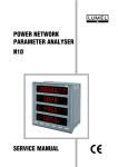
PARAMETER TRANSDUCER - ANALYZER P10 TYPE SERVICE MANUAL CONTENTS: 1. APPLICATION ----------------------------------------------------------------------------- 4 2. DELIVERY SET - OPERATIONAL SAFETY -------------------------------------- 5 3. INSTALLATION --------------------------------------------------------------------------- 6 3.1. FITTING ------------------------------------------------------------------------------ 6 3.2. EXTERNAL CONNECTION DIAGRAMS ------------------------------------ 7 4. PROGRAMMING ------------------------------------------------------------------------- 11 4.1. FACEPLATE DESCRIPTION --------------------------------------------------- 11 4.2. P10 OPERATING MODES ------------------------------------------------------ 13 4.2.1. MEASURING MODE ------------------------------------------------------- 14 4.2.1.1. EXTREME VALUES ---------------------------------------------- 17 4.2.1.2. MEASUREMENT OF VOLTAGE AND CURRENT HARMONICS -------------------------------- 17 4.2.2. SETUPS OF THE RTC TIME -------------------------------------------- 18 4.2.3. CONFIGURATION OF PARAMETERS PARAMETERS ---------- 19 4.2.4. PROGRAMMING OF ALARMS ------------------------------------------ 21 4.2.5. PROGRAMMING OF ANALOG OUTPUTS -------------------------- 22 5. ENTRIES TO THE TARIFF CHANGE ----------------------------------------------- 24 6. ERROR CODES -------------------------------------------------------------------------- 26 7. TECHNICAL DATA ----------------------------------------------------------------------- 27 8. EXECUTION CODES -------------------------------------------------------------------- 31 3 1. APPLICATION The P10 transducer-analyzer is destined to measure voltages and currents in a three or four-wire power network, in symmetric or asymmetric systems and enables the conversion of network parameters into four standard analog current signals. The RS-485 interface with the MODBUS transmission protocol makes possible the application of this P10 transducer-analyzer in computer systems. This transducer enables the measurement of root-mean-square values of voltage and current, active, reactive, apparent power and energy, power factors, frequency, active and average power e.g. 15 min., harmonic distorsion coefficients for each phase and harmonic measurement from 1 to 25 th. Moreover, this P10 transducer-analyzer shows the real time and the time of extremal value occurences. It has 4 relay outputs and 3 two-state inputs to switch the rate of energy counters. The P10 transducer-analyzer is destined for producers and distributors of electrical energy and individual users. Quantities measured and calculated by the P10 transducer-analyzer: • phase voltages U1, U2, U3, • phase-to-phase voltages U12, U23, U31, • average three-phase voltage Us • average phase-to-phase voltage Umf • average three-phase current Is • phase currents I1, I2, I3 • phase active powers P1, P2, P3, • phase reactive powers Q1, Q2, Q3, • phase apparent powers S1, S2, S3, • phase active power factors Pf1, Pf2, Pf3, • ratio between reactive and active power factors tgj1, tgj2, tgj3 • average three-phase power factors Pf, tgj • phase power factors tgj1, tgj2, tgj3 • three-phase active, reactive and apparent powers P, Q, S • average active power, e.g. 15 min. PAV • three-phase active, reactive and apparent energy in four rates (tariffs) Ept1-4, Eqt 1-4, Est 1-4 • frequency f • full coefficients of distorsion by harmonics for phase voltages and phase currents THDU1, THDU2, THDU3, THDI1, THDI2, THDI3, • phase voltage and phase current harmonics up to 25th 4 Maximal and minimal values accessible with the date and time of their occurence are measured for all quantities. Additionally, there is the possibility to adapt the P10 transducer-analyzer to external measuring transformers. The updating time of all accessible quantities does not exceed 1 second. All quantities and configurating parameters are accessible through the RS-485 interface. 2. DELIVERY SET - OPERATIONAL SAFETY With the P10 transducer-analyzer we deliver: - a service manual, - a guarantee card, - 3 bolts to fix the transducer on a wall. In case of the execution with a serial interface, we deliver additionally: - a service manual of the serial interface, - a service manual of the WizPar program, - a diskette named „WizPar Visualization Program”. When unpacking the P10 transducer-analyzer, please check whether the type and execution code on the data plate correspond to the order. Symbols located in this service manual mean: ! Especially important. One must acquaint with this before connecting the instrument. ? Read carefully. One must take note of this when the instrument is working inconsistently to the expectations. P10 transducer-analyzers are destined to be mounted on panels or walls. In the range of operational safety they are in conformity with the IEC 1010 standard requirements. Remarks concerning the operator safety: • The installation and meter connection should be operated by qualified personnel. • One must take into consideration all accessible protection requirements. • Before switching the instrument on, one must check the correctness of the network lead connection. • In case of the protection terminal connection with a separate lead one must remember to connect it before the connection of network leads. • Do not connect the transducer to the network through an autotransformer. • Before taking the transducer housing out one must turn the supply off. • The removal of the transducer housing during the guarantee period may cause its cancellation. 5 3. INSTALLATION 3.1 Fitting way. P10 transducer-analyzers are adapted to be installed on a DIN rail or on a wall by means of bolts. Fig. 1. External dimensions and fitting way on a wall 6 3.2. External connection diagrams Direct measurement in a three-phase network Half-intermediate measurement via 2 current transformers in a three-phase network 7 Intermediate measurement via 3 current transformers and 2 or 3 voltage transformers in a 3-phase network. Steering inputs IN1 IN2 IN3 RS485 GND A B Analog outputs AL1 AL2 AL3 AL4 OU1 OU2 OU3 OU4 26 27 28 29 30 31 32 33 34 35 36 37 38 39 40 41 42 43 44 45 46 47 48 49 50 P10 1 2 3 4 5 6 7 8 9 a A b a B A 23 85...250 V Supply b B L1 L1 L2 L2 L3 L3 P1 a A S2 S1 ba BA ba BA b B P2 S1 S2 P1 P2 Fig. 2. Connection diagrams of the P10 transducer - analyzer in a three-phase network Direct measurement in a four-wire network 8 25 Half-intermediate measurement in a four-wire network via 3 current transformers Intermediate measurement via 3 current transformers and 2 or 3 voltage transformers in a four-wire network. Steering inputs IN1 IN2 IN3 RS485 GND A B Analog outputs AL1 AL2 AL3 AL4 OU1 OU2 OU3 OU4 26 27 28 29 30 31 32 33 34 35 36 37 38 39 40 41 42 43 44 45 46 47 48 49 50 P10 1 2 3 4 5 6 7 8 9 a A L1 b a B A 25 85...250 V Supply b B L1 L2 L2 L3 L3 N 23 11 N S1 S2 P2 P1 S1 S2 P2 P1 S 1 S2 P2 P1 a A ba BA ba BA b B Fig. 3. Connection diagrams of the P10 transducer-analyzer in a four-wire network. 9 Note: To connect the RS-485 interface, ( a double twisted pair of conductors in a screen is recommended. Connect the screen in one point to the ground. ! Fig. 8. Connection way of the RS-485 interface 10 4. PROGRAMMING 4.1. Faceplate description Fig. 5. View of the P10 transducer-analyzer The P10 transducer-analyzer has 6 functional keys and an LCD 2 x 16 character display. Parameter values are compiled in two lines. By means of keys, the user can choose any optional quantity. The assignement of each key is as follows. Acceptation key - ENTER Key to displace to the right Key to decrease the value Key to increase the value Key to displace to the left Esc Clearing key - Esc 11 key - in the programming mode: acceptation of the introduced value. keys - in the measurement mode, these keys allow to displace on the twodimensional parameter table. - in the programming mode they enable the position change of the cursor and allow to control the display contrast keys - in the measurement mode, these keys allow to displace on the twodimensional parameter table - in the programming mode, they serve to change the introduced value Esc key - this key enables the resignation in any moment of the operation In the measurement mode the display has the following view: 1 2 3 n n n x x 4 x 5 x 6 x 7 8 9 A I v v 10 11 12 13 14 15 16 v nnn - name of the quantity acc. the table No 2 xxxxxx - value a a v v a a vvvvv - unit aaaa - state of relay outputs ( - non active, output number - active) 12 4.2 Working modes of P10 transducer-analyzers The P10 transducer-analyzer has 5 working modes, set down in the table 1. Working modes Table 1 Calling Mode Calling symbol Name Measuring Input Output assumptive Through the input to another mode Clock setting RTC Time In SETUP procedure Esc , or after the last parameter Parameter configuration Parameters In SETUP procedure Esc , or after the last parameter Alarm programming Alarms In SETUP procedure Esc , or after the last parameter Analog Outputs In SETUP procedure Esc , or after the last parameter Analog output programming After the transducer-analyzer switching on, the following message is reported. 1 2 3 P 1 0 y y 4 / 5 6 7 8 v . x x m m / d 9 10 11 12 13 14 15 16 L d U M E L h h : m m where: v.xx - is the number of the current program version yy/mm/dd - defines the current date hh:mm - current hour 13 After making tests, the transducer-analyzer transits into the measuring mode and the last set quantity is indicated keys during 3 seconds. The entry into the SETUP procedure follows after pressing The entry into the other modes is carried out by the SETUP procedure. By means of keys one must choose the suitable mode „RTC Time”, „Parameters”, „Alarms”, „Analog Outputs” and accept the chosen mode by the key. The return from other modes to the measuring mode is carried out by the Esc or key after the last parameter. 4.2.1. Measuring mode In the measuring mode the quantity value is displayed according the table settled by the manufacturer. The quantity change is carried out by means of the measuring mode. keys. Quantities displayed in Table 2 Pav U12 U1 I1 P1 Q1 S1 PF1 tg1 f HU1 HI1 U23 U2 I2 P2 Q2 S2 PF2 tg2 f HU2 HI2 U31 U3 I3 P3 Q3 S3 PF3 tg3 f HU3 HI3 UPP U I P Q S f Ept1 Eqt1 Est1 Ept2 Eqt2 Est2 Ept3 Eqt3 Est3 Ept4 Eqt4 Est4 14 PF tg Quantity names, symbols and units Item Quantity name 1 lack of quantity Table 3 Symbol Unit off 2 L1-L2 phase-to-phase voltage 3 L2-L3 phase-to-phase voltage U12 (M,k)V U23 (M,k)V 4 L3-L1 phase-to-phase voltage U31 (M,k)V 5 average phase-to-phase voltage UPP (M,k)V 6 L1 phase voltage 7 L2 phase voltage U1 (M,k)v U2 (M,k)V 8 L3 phase voltage U3 (M,k)V 9 average 3-phase voltage U (M,k)V 10 Current in L1 phase line 11 Current in L1 phase line I1 (k)A I2 (k)A 12 Current in L1 phase line I3 (k)A 13 average 3-phase current I (k)A 14 average active power 15 active power of L1 phase Pav (G,M,k)W P1 (G,M,k)W 16 active power of L2 phase P2 (G,M,k)W 17 active power of L3 phase P3 (G,M,k)W 18 3-phase active power 19 3-phase active energy - Tariff 1 P (G,M,k)W Ept1 (G,M,k)Wh 20 3-phase active energy - Tariff 2 Ept2 (G,M,k)Wh 21 3-phase active energy - Tariff 3 Ept3 (G,M,k)Wh 22 3-phase active energy - Tariff 4 23 Reactive power of L1 phase Ept4 (G,M,k)Wh Q1 (G,M,k)Var 24 Reactive power of L2 phase Q2 (G,M,k)Var 25 Reactive power of L3 phase Q3 (G,M,k)Var 26 3-phase reactive power 27 3-phase reactive energy - Tariff 1 Q (G,M,k)Var Eqt1 (G,M,k)Varh 28 3-phase reactive energy - Tariff 2 Eqt2 (G,M,k)Varh 29 3-phase reactive energy - Tariff 3 Eqt3 (G,M,k)Varh 30 3-phase reactive energy - Tariff 4 Eqt4 (G,M,k)Varh 15 Quantity names, symbols and units Item Quantity name Table 3 (continuation) Symbol Unit 31 Apparent power of L1 phase 32 Apparent power of L2 phase S1 G,M,k)VA S2 (G,M,k)VA 33 Apparent power of L3 phase 34 3-phase apperent power S3 (G,M,k)VA S (G,M,k)VA 35 3-phase apperent energy - Tariff 1 36 3-phase apperent energy - Tariff 2 Est1 (G,M,k)VAh Est2 (G,M,k)VAh 37 3-phase apperent energy - Tariff 3 38 3-phase apperent energy - Tariff 4 Est3 (G,M,k)VAh Est4 (G,M,k)VAh 39 L1 phase power factor 40 L2 phase power factor PF1 41 L3 phase power factor 42 3-phase power factor PF3 43 tgϕ coefficient of L1 phase 44 tgϕ coefficient of L2 phase tg1 45 tgϕ coefficient of L3 phase 46 3-phase tgϕ coefficient tg3 PF2 PF tg2 tg 47 THD coefficient of L1 phase voltage 48 THD coefficient of L2 phase voltage HU1-THD % HU2-THD % 49 THD coefficient of L3 phase voltage 50 THD coefficient of L3 phase cuurent HU3-THD % HI1-THD % 51 THD coefficient of L3 phase cuurent 22 THD coefficient of L3 phase cuurent HI2-THD % 53 frequency 16 HI3-THD % f Hz 4.2.1.1. Extreme values The monitoring of minimal and maximal values is carried out when after pressing the or 1 2 z x z yy/mm/dd hh:mm xxxxxx vvvvv and keys, the following message is shown on the display: 3 4 5 6 7 8 9 10 11 12 13 14 15 16 y y / m m / d d x x x x v v v h v h : m m v - ↑ maximum sign, ↓ minimum sign - date of extremum occurence - time of extremum occurence - value - unit The clearing of external values follows after pressing the Esc key during their monitoring. Note: The clearing of external values of the Pav parameter follows after zeroing them in the PARAMETERS mode. 4.2.1.2 Measurement of current and voltage harmonics The choice of harmonics is carried out by pressing Esc and during 3 sec. THD coefficients values and harmonic contents from 2 up to 25th can be reviewed by means of keys moving on the two-dimensional coefficient table. 17 Harmonics displayed in the measuring mode. HU1-THD The key Table 4 HU1-04 HU1-05 HU1-06 HU1-07 ... HU1-24 HU1-25 HU2-THD HU2-02 HU2-03 HU2-04 HU2-05 HU2-06 HU2-07 ... HU2-24 HU2-25 HU3-THD HU3-02 HU3-03 HU3-04 HU3-05 HU3-06 HU3-07 ... HU3-24 HU3-25 HI1-THD HI1-02 HI1-03 HI1-04 HI1-05 HI1-06 HI1-07 ... HI1-24 HI1-25 HI2-THD HI2-02 HI2-03 HI2-04 HI2-05 HI2-06 HI2-07 ... HI2-24 HI2-25 HI3-THD HI3-02 HI3-03 HI3-04 HI3-05 HI3-06 HI3-07 ... HI3-24 HI3-25 enables the displacement downwards of 3 positions. This function enables si- multaneously to follow harmonic values for currents and voltages of the same phase. 4.2.2. Setups of the RTC Time After the entry into the SETUP procedure one must choose the RTC mode by means of keys and press the where: yy mm dd hh mm 18 1 2 3 R T C y y - year - month - day - hour - minute 4 / key. The following values are displayed: 5 6 7 8 T i m e m m / d 9 d 10 11 12 13 14 15 16 h h : m m Required parameters can be set up by means of or key, and the digit value by the or keys, the quantity by the . key. The active position is signalled by the cursor. One must accept settled values by the key or resign by pressing the Esc key and back to the measuring mode. 4.2.3. Configuration of PARAMETERS parameters This mode serves to settle transducer-analyzer parameters. The entry into the configuration mode is protected by the access code if a code different from zero has been introduced. For the code 0000, the inquiry for the password is omitted. If the access code is different from zero, there is the possibility to review parameters but changes are blocked. In the configuration mode quantities acc. the table 5 are settled Set of parameters Item Parameter name Table 5 Designation Range Assumptive value 1 Introduction of the access code Password? 0000...9999 0000 2 Setup of transducer manufacturers parameters Set Defaults? Y,N N 3 Ratio of the current transformer I Ratio 1...20000 1 4 Ratio of the voltage transformer U Ratio 1...4000 1 5 Cancellation of the counters Clear E*t? Y,N N 6 Cancellation of the Pav power averaged time (e.g. 15 min), Pav (max and min. value) Clear Pav Y,N N 7 Averaging time of the Pav power Pav Time 15, 30, 60 15 8 Synchronization of Pav power averaging Pav - through the clock, - through the moving window Pav Window? Synchro, Moving Synchro 9 Transducer address in the network Slave Address 0,1,...,247 1 19 Item Parameter name 10 Serial interface rate 11 Mode of the MODBUS interface 12 Change of access code Designation Range Assumptive value Baud Rate 600, 1200, 2400, 4800, 9600, 19200 19200 off, 8n1 ASCII, 7e1 ASCII, Modbus Mode 7o1 ASCII, 8n2 RTU, 8e1 RTU, 8o1 RTU Password 0000,..., 9999 8n2 RTU 0000 Designations : n - (no parity), lack of parity e - (even parity), bit of parity control o - (odd parity), bit of odd parity control. Required values are settled in the configuration mode by means of keys. The active position is marked off by the cursor. The settled quantity can be accepted by the key or cancelled by the Esc key. The pressure of the key causes the setup on the succes- sive parameter, and after the last parameter, remembers the set up values and causes the exit from the Parameters mode. Note: When changing the working mode and the interface baud rate, the transducer reset follows. 20 4.2.4. Programming of Alarms Any arbitrary quantity of the group of 41 parameters (table 8) can be assigned to the alarm output. Moreover, it is possible to: • set up the switch on tresholds, • set up the switch off tresholds, • settle the delay Alarms mode Item Table 6 Parameter name Designation 1 Two-state output 1 - quantity 2 Two-state output 1 - switch on 3 Two-state output 1 - switch off value Range Assumptive value Alarm1 Param table 8 I1 Alarm1 On -120...0...120[%] 101 -120...0...120[%] 99 Alarm2 Param Alarm1Off table 8 I2 5 Two-state output 2 - switch on Alarm2 On -120...0...120[%] 101 6 Two-state output 1 - switch off value Alarm2 Off -120...0...120[%] 99 7 Two-state output 3 - quantity Alarm3 Param table 8 I3 8 Two-state output 3 - switch on Alarm3On -120...0...120[%] 101 9 Two-state output 3 - switch off value Alarm3 Off -120...0...120[%] 99 4 Two-state output 2 - quantity 10 Two-state output 4 - quantity 11 Two-state output 4 - switch on 12 Two-state output 3 - switch off value 13 Delay in alarm operation Example: Alarm4 Param table 8 I Alarm4 On -120...0...120[%] 101 Alarm4 Off -120...0...120[%] 99 Alarms Delay 0...100 [s] 0 1 2 3 4 5 6 A l a r m 1 7 8 9 P a 10 11 12 13 14 15 16 r a U 1 m The voltage of phase 1 has been assigned to the 1st relay output 21 4.2.5. Programming of Analog Outputs A continuous output current signal can be assigned to any arbitrary measured or calculated quantity from the group of 41 parameters. Moreover, it is possible to: • set up the changing window of the input signal, • choose the current range: 0...20, 4...20, 0...5, 0...10 mA Set of Analog Outputs mode parameters Item 1 Parameter name Quantity on the continuous output No 1 Table 7 Designation Range Assumptive value AnOut1 Param table 8 off 2 Lower value of the input range AnOut1 Low [%] -120...0...120 0 3 Upper value of the input range AnOut1 Hi [%] -120...0...120 100 4 Continuous output type AnOut1 Zero [mA] 0, 4, 5, 10 4 5 Quantity on the continuous output No 2 AnOut2 Param table 8 off 6 Lower value of the input range AnOut2 Low [%] -120...0...120 0 7 Upper value of the input range AnOut2 Hi [%] -120...0...120 100 AnOut2 Zero [mA] 0, 4, 5, 10 4 AnOut3 Param table 8 0ff 8 Continuous output type 9 Quantity on the continuous output No 3 10 Lower value of the input range AnOut3 Low [%] -120...0...120 100 11 Upper value of the input range AnOut3 Hi [%] -120...0...120 100 AnOut3 Zero [mA] 0, 4, 5, 10 4 AnOut4 Param table 8 off 12 Continuous output type 13 Quantity on the continuous output No 4 14 Lower value of the input range AnOut4 Low [%] -120...0...120 0 15 Upper value of the input range AnOut4 Hi [%] -120...0...120 100 AnOut4 Zero [mA] 0, 4, 5, 10 4 16 Continuous output type Note: the analog output type is designed by: 0 4 5 10 22 - defines the current output - defines the current output - defines the current output - defines the current output 0... 20 mA range 4... 20 mA range 0... 5 mA range 0... 10 mA range Tablica 8 Code Designation 40 OFF 39 U1 Quantity lack of quantity L1 phase voltage 38 I1 current in the L1 phase line 37 P1 L1 phase active power 36 Q1 L1 phase reactive power 35 S1 34 PF1 33 tg1 L1 phase tgj coefficient 32 U2 L2 phase voltage L1 phase apperent power L1 phase power factor 31 I2 current in the L2 phase line 30 P2 L2 phase active power 29 Q2 L2 phase reactive power 28 S2 27 PF2 L2 phase power factor L2 phase apperent power 26 tg2 L2 phase tgj coefficient 25 U3 L3 phase voltage 24 I3 current in the L3 phase line 23 P3 L3 phase active power 22 Q3 L3 phase reactive power 21 S3 20 PF3 L3 phase power factor L3 phase apperent power 19 tg3 L3 phase tgj coefficient 18 U average 3-phase voltage 17 I average 3-phase current 16 P three-phase active power 15 Q three-phase reactive power 14 S three-phase apperent power 13 PF three-phase power factor 23 Table 8 (continuation) Code Designation Quantity 12 tg 11 f 3-phase tgj coefficient 10 U12 9 U23 L2-L3 phase-to-phase voltage 8 U31 L3-L1phase-to-phase voltage 7 UPP average phase-to-phase voltage 6 Pav average active power 5 HU1 THD coefficient by harmonic of L1 phase voltage 4 HU2 THD coefficient by harmonic of L2 phase voltage 3 HU3 THD coefficient by harmonic of L3 phase voltage 2 HI1 THD coefficient by harmonic of L2 phase current 1 HI2 THD coefficient by harmonic of L1 phase current 0 HI3 THD coefficient by harmonic of L3 phase current frequency L1-L2 phase-to-phase voltage 5. ENTRY TO THE TARIFF CHANGE Steering inputs to the tariff change have a constant function - the tariff switching. Tariffs are used for the counting of the 3-phase tariff energy (four tariff energy counters, Epti ,Eqti ,Esti). When there is a lack of signals on outputs, the energy is counted in Ept1 , Eqt1 ,Est1. counters. The signal switching on successive outputs causes the switch-over of the counters. Input 1 Input 2 Input 3 Tariff 0 1 0 0 0 0 1 0 0 0 0 1 tariff 1 tariff 2 tariff 3 tariff 4 where: 1 - steering voltage: 24 V ±50% 0 - lack of steering voltage 24 Working modes of the P10 transducer-analyzer. Fig.6. Working modes of the P10 transducer 25 6. ERROR CODES During the transducer-analyzer operation, messages about errors can occur. Error causes are described below: Invalid Value - when during measurementg the voltage or current is too small Pfi ,tji below 5% Un below 5% In f below 5% Un - the full interval of the Pav power averaging time is not expired, Invalid Min - Lack of possibility to define the minimal value. (lack of current, usually after the transducer switching on or cancellation the extremes). Invalid Max - Lack of possibility to define the maximal value. (lack of current, usually after the transducer switching on or cancellation the extremes). For THD and harmonic measurements U out of range - voltage under 10% Un I out of range - current under 10% In f out of range - frequency out of the 47...52 Hz range 26 7. TECHNICAL SPECIFICATIONS Measuring ranges and admissible measuring errors are shown in the table 9. Table 9 Measured quantity Range Basic error Remarks Voltage U i 100.0 V (Ku=1) 400.0 V (Ku=1) for Ku¹1:....400 kV 1.000 A (Ki=1) 5.000 A (Ki=1) for Ki¹1:....20.00 kA ±(0.2% m.v. +0.1% of range) Ku=1...4000 (max 400 kV) ±(0.2% m.v. +0.1% of range) Ki=1...20000 (max 20 kA) Current I i Active power P i 0.0...(-)1999.9 (Wh) for Ku¹1, Ki¹1 Mean active ...(-)1999.9 MW powerPAV (MWh) Active energy EnP Reactive power 0.0...(-)1999.9 (Varh) for Ku¹1, Ki¹1 Qi ...(-)1999.9 MVar Reactive energy (MVarh) EnQ 0.0...(-)1999.9 (VAh) Apparent power for Ku¹1, Ki¹1 Si ...(-)1999.9 MVA Apparent energy (MVAh) EnS ±(0.5% m.v. +0.2% of range) ±(0.5% m.v. +0.2% of range) ±(0.5% w.m +0.2% of range) Active power factor Pf i -1.00...0.00 ... 1.00 ±1% m.v. ±2c Pf=Power factor=P/S Coefficient ϕi tgϕ -99.99...0...99.99 ±1% m.v. ±2c error in the range -60...0...+60° Frequency f 20.0...500.0 Hz ±0.5% m.v. THD U, THD I Harmonics 0.2...100 % ±5% m.v. ±2c error in the range 10...120% U, I 47...52 Hz 27 where: Ku - voltage transformer ratio Ki - current transformer ratio THD U - full coefficient of distortion by voltage harmonics THD I - full coefficient of distortion by current harmonics m.v. - measured value c - the smallest gignificant digit of the display Power consumption - in the supply circuit - in the voltage circuit - in the current circuit £ 10 VA £ 0.2 VA £ 0.1 VA Supply voltage 85...250 V DC or AC, 40...400 Hz Read-out field display: LCD 2 x 16 characters Analog output 4 outputs 0...20 mA, 4...20 mA, 0...5 mA, 0...10 mA accuracy: 0.2% Relay outputs 4 relays: voltageless make contacts load capacity: 250 V~ / 0.5 A~ Steering input 3 inputs 0/24 V DC ±50% to steer 4 energy counter tariffs Serial interface RS 485 Transmission protocol MODBUS Transducer - analyzer reaction about supply decays and returns: - preservation of data and transducer state during decays (accumulator support) - continuation of operation after the supply return Protection grade ensured by the housing: - screw terminals IP 20 - housing IP 40 Weight 0.7 kg Dimensions 152 x 73.2 x 118.2 mm Fitting on a 35 mm DIN rail Maximal lead cross-section 4 mm2 28 Reference conditions and rating operating conditions - input signal: 0...0.01...1.2 In; 0...0.01...1.2 Un; for voltage, current, power and energy in a 4-wire network 0...0.01...1.2 In; 0...0.1...1.2 Un; for voltage, current, power and energy in a 3-wire network 0...0.1...1.2 Un for frequency, 0...0.05...1.2 In; 0...0.05...1.2 Un; for Pf and tϕ coefficients, frequency 45...65; sinusoidal (THD ≤ 8%) 0.1...1.2 In ; 0.1...1.2 Un ; 47...52 Hz ; for THD U, THD I and harminics - power factor -1...0...1 - ambient temperature 0...23...55°C - humidity 25...95% (condensation inadmissible) - supply 85...250 V DC or AC, 40...400 Hz - admissible peak factor: - current - voltage 2 2 - storage temperature -20...85°C - external magnetic field 0...40...400 A/m - overload of short duration (5 sec.) - voltage inputs 2 Un (max.1000 V) - current inputs 10 In - working position optional - heating time 5 min. 29 Additional errors in % of the basic error - from ambient temperature changes: < 50%/10°C Standards fulfilled by the transducer-analyzer: Electromagnetic compatibility: - immunity acc. EN-50082-2 (1996) - emission acc. EN50081-2 (1996) - harmonic measurement acc. EN50160 Security requirements: in compliance with IEC 1010-1+A1 (1996): • insulation ensured by the housing: double, • insulation between circuits: basic, • installation category: III, • pollution degree: 2, • maximal working voltage in relation to the earth: 600 V AC 30 ? 8. EXECUTION CODES Table 10 Transducer - analyzer P10 Input current In: 1 A (X/1) 5 A (X/5) as per order* Input phase voltage Un: 100 V 400 V as per order* X X X XX X 1 2 9 1 2 9 Digital output: without interface with an RS485 interface Supply voltage: 85...250 V DC or AC, 40...400 Hz as per order* Kind of executions: standard custom-made 0 1 0 9 00 XX Acceptance tests: without additional requirements with a quality inspection certificate as per customer′s agreements** 0 1 X * after agreement with the manufacturer ** the code number will be settle by the manufacturer ORDERING EXAMPLE: code P10-2-1-1-0-00-1-means: a P10 transducer - analyzer with a 5 A input current, input phase voltage: 100V, RS-485 interface, supply voltage: 85...250 V DC / AC, standard execution and with a quality inspection certificate. 31 SALES PROGRAMME MEASUREMENT n DIGITAL PANEL METERS CONTROL n BARGRAPH INDICATORS n MEASURING TRANSDUCERS RECORDING n ANALOG PANEL METERS (DIN INSTRUMENTS) n DIGITAL CLAMP-ON METERS n PROCESS and DOMESTIC CONTROLLERS n CHART AND SCREEN RECORDERS n POWER CONTROL UNITS and FREQUENCY INVERTERS n AUTOMOTIVE DASHBOARD INDICATORS n STATIONARY and PORTABLE CALIBRATORS n MEASUREMENT ACCESSORIES ( SHUNTS, SENSORS, TRANSFORMERS) n MEASURING SYSTEMS ( energy, heat, control, measurement ) n CUSTOM-MADE PRODUCTS WE ALSO OFFER OUR SERVICES IN THE PRODUCTION OF: n ALUMINIUM ALLOY PRESSURE CASTINGS n PRESSURE CASTING DIES and INJECTION MOULDS n PRECISION ENGINEERING and THERMOPLASTIC PARTS QUALITY PROCEDURES: According ISO 9001 international requirements. For more detailed information please write to or phone our Export Dept P10-KZ1268/2006 Lubuskie Zak³ady Aparatów Elektrycznych LUMEL S.A. ul. Sulechowska 1 65-950 Zielona Góra - Poland tel.: (48-68) 32 95 100 fax: (48-68) 32 95 101 e-mail: [email protected] http://www.lumel.com.pl Export Department: fax: (48-68) 325 40 91 Tel: (48-68) 329 53 02 or 53 04


